Table of Contents
Advertisement
Installation Manual
By Firstech LLC, Version: 1.0
Applicable to the following remote start system:
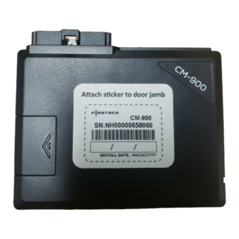
CM-900 – Auto Only Starter Control Module
This device complies with Part 15 of the FCC rules. Operation is subject to the following conditions;
(1) This device may not cause harmful interference.
(2) This device may accept any interference received, including interference that may cause undesired operation.
CAUTION: Changes or modifications not expressly approved by the party responsible for compliance could void the
user's authority to operate this device.
WWW.FIRSTECHDATA.COM
Advertisement
Table of Contents

Related Manuals for Firstech CM-900


Summary of Contents for Firstech CM-900
- Page 1 By Firstech LLC, Version: 1.0 Applicable to the following remote start system: CM-900 – Auto Only Starter Control Module This device complies with Part 15 of the FCC rules. Operation is subject to the following conditions; (1) This device may not cause harmful interference.
- Page 2 Alternator Sensing – Option 2-10 Setting 3 ..................7 Assumed Timed Crank – Option 2-10 Setting 4 ................... 7 Diesel Timer ............................8 CM-900 Wiring Schematic (Remote Start) .................... 9 Option Programming Tables ....................... 14 Option Menu Descriptions ........................16 Option Programming ...........................
-
Page 3: Introduction
Introduction Thank you for purchasing a Firstech remote start system for your vehicle. The following installation manual is intended for experienced and authorized remote start technicians. This is not a tutorial on how to install. We highly recommend that you contact your local Firstech dealer and seek professional installation. -
Page 4: Installation Basics
Installation Basics If you are new to installing Firstech remote start units, we highly recommended that you review this manual in its entirety prior to installing your first unit. Key Points to Consider Before Installation: The two remotes are preprogrammed to the unit Page 5 This system is designed for ease of installation and the two included remotes are preprogrammed. -
Page 5: Remote Code Routine(S)
STEP 2, you can code additional remotes by tapping the Lock button on the remote(s). The parking lights will flash once confirming each additional remote. The CM-900 can store up to three remotes. Exiting Programming: Programming is a timed sequence. The parking lights will flash twice signaling the end of programming mode. -
Page 6: Common Procedures
“Smart Resting Mode”. Traditional tach sensing is highly recommended for colder climates. Tach Sensing – Option 2-10 Setting 2 Tach sensing mode requires a connection made with the yellow/black wire on Connector 3. Firstech recommends using an injector, coil or other tach source for tachometer sense. IMPORTANT: The tach must be programmed before remote starting. -
Page 7: Alternator Sensing – Option 2-10 Setting 3
STEP 2: Test wire and make connection. With the vehicle off the wire should test 0 Volts AC. At idle the tach wire should test between 1 to 5 Volts AC. As the vehicle RPM’s increase the voltage on the meter will also increase. -
Page 8: Diesel Timer
Diesel Timer The CM-900 module has a built in Diesel Timer to allow the vehicle’s glow plug wire to heat up. There are multiple time settings on this unit, 3 to 99 seconds. This will allow the ignition to power up and then... -
Page 9: Cm-900 Wiring Schematic (Remote Start)
CM-900 Wiring Schematic (Remote Start) - Page 10 Pin 8 Black - Ground negative (-) input. This wire must be connected to the vehicle’s ground. Connector 2 (CN2) Blade Connector and Cartridge The CM-900 slot gives you the ability to use the Blade-AL and Blade-TB modules from Firstech and ADS. With these modules you can virtually eliminate all wire connections between your control module and bypass module.
- Page 11 Pin 10 Red/White – This wire requires a negative (-) pulse input for triggering the remote start sequence. This wire allows you to use the CM-900 as a slave remote starter that can be controlled by a factory OEM remote.
- Page 12 Pin 11 Red - This wire requires a (+) pulse input for triggering the remote start sequence. This wire allows you to use the CM-900 as a slave remote starter that can be controlled by a factory OEM remote. Pin 12 Yellow/Black - Engine sensing input. This wire is connected to the vehicle’s Tach or Alternator wire and is required if you are not using the tachless sense setting.
- Page 13 Connector 7 (CN7), 2-Pin (FT-Temp Sensor) This port is for FT-Temp Sensors only. FT-Temp Sensor is formally known as Thermister. Connector 8 (CN8), 4-Pin (Pre-wired Antenna Cable) Pin 1 Yellow - RX input. This wire receives the signal from remote. Pin 2 White - TX output.
-
Page 14: Option Programming Tables
Option Programming Tables Optional Optional Optional Feature Default Setting - I Setting - II Setting - III Setting - IV Unlock Before, Lock After Lock After Shutdown 1-01 Lock After Start Only Starting Only 1-02 Lock / Unlock Pulse Duration 0.8 sec 2.5 sec 0.125 sec... - Page 15 Tachless (Voltage Running, Automatic Sensing, Automatic Transmission Only) Transmission Only) 2-11 Advanced Tachless Standard – +0.2 Seconds to +0.6 Sec to Crank 2-12 Minimum Crank Time Standard Crank Time Time MIN(0.2sec) 2-13 Timer Mode Optional Optional Optional Feature Default Setting - I Setting - II Setting - III Setting - IV...
-
Page 16: Option Menu Descriptions
FO4 - Lock after shutdown only: will send a lock command only after the CM-900 has successfully shut down. Note: It will not provide an output if the CM-900 is shut down with an emergency override input. (i.e. hood pin, or foot brake input) 1-02 Lock / Unlock Pulse Duration: This does not affect the behavior of the factory arm output (orange wire) or factory alarm disarm output (orange/white wire). - Page 17 FO1 - Off: (default) FO2 - On: This option (when activated with the Firstech remote or Drone) will provide a door lock output when the foot brake is applied or 12 Volts is applied to the foot brake input on the CM-900.
- Page 18 The CM-900 will also provide a door unlock output as soon as the key is turned off or 12v ignition is removed from the CM-900. FO3 - RPM locking: (Tach input is required for this option to operate properly.) This option will provide a door lock output at approximately 20% RPM over the programmed idle tach output.
- Page 19 FO2 - Previous tach reading: This option will set the CM-900 to record the idle voltage which it is being programmed. The CM-900 will release the starter once the idle tach voltage is met.
- Page 20 FO1 - 3 hour cycle: (4 minute runtime, 8 minute runtime for diesel) Once Timer Mode is enabled (see feature 2-13) the CM-900 will wait 3 hours, remote start and run for 4 minutes unless the cold start feature is enabled. If this is the case, the CM-900 will check the temperature once every 3 hours.
- Page 21 Note: feature 2-10 must be set to option 3 in order for it to work properly. If there is tach signal input to the CM-900 either analog or data interface module, this option will not operate consistently.
- Page 22 2-13 Timer Mode: (Note: Must be set to on in order to operate timer mode).This feature enables the user to activate and deactivate Timer Mode (see option 2-06) using the Firstech remote or accessory (see the user manual for that remote for instructions).
- Page 23 “on” position and press the foot brake 10 times within 10 seconds. 3-13 Defrost Output Temp Control: This feature will determine the temperature at which the CM-900 will provide an output on any POC programmed with setting 17 or 21 (defrost and defrost 2).
- Page 24 would be good for many front, rear, or rear view mirror defrost functions that may need a longer latched output time.) FO4 - Latched for Entire Runtime: (Remote start runtime based off of feature 2-07 option setting) This feature will provide a latched output for the entire remote start runtime on any POC programmed with setting 17 (defrost) with timing based off of feature 3-12 option settings.
- Page 25 FO4 - With ignition removed: This option will trigger AUX 1 (output time based on feature 4-01) as soon as Ignition input is removed from the CM-900. (I.e. this feature can be used with a manual transmission vehicle to open the door input circuit on the CM-900 for a set period of time when reservation mode is complete in order to prevent the dome light from cancelling reservation mode.)
- Page 26 FO1 - Off: (default) This option does not provide a low battery indication. FO2 - On: This option will provide an alert to any Firstech 2 Way LCD remote or Drone when the vehicle’s battery voltage (at the CM-900 power connector) drops to 11.7volts. Note: the Firstech 2 way LCD remote must be within range of the vehicle to receive the low battery alert and this option must be set in order to receive low battery alerts to Drone.
- Page 27 POC 1 – Green/White • Negative Parking Light Output: (default setting) This channel will provide a 250mA (-) negative output when the CM-900 is armed (function also POC setting 1) POC 2 – Blue/Green • Lock: (default setting) This channel will provide a 250mA output with the lock/arm command.
-
Page 28: Option Programming
Option Programming How to Program Options There are two ways to set options on the CM-900 control modules. You can use the FT-OP500 or most Firstech remotes. The remotes include 4 or 5 button 1 and 2 Way remotes. Option Programming Using the FT-OP500 The OP500 can be used to change anything in the Option Tables. - Page 29 STEP 1: Select the option you wish to program. Use the correct remote table below: How to Program Options With 2 Way Remotes with Separate Lock and Unlock Buttons Lock + Unlock for 3 Hold Trunk Tap Key Tap Lock Tap Start Option seconds then Lock +...
-
Page 30: Troubleshooting
Can I use any other Firstech remotes with this system? A: Yes, the CM-900 control module is designed to only work with 4 Pin antennas and compatible remotes. It does not work with 6 to 6 Pin antennas. - Page 31 Is the CM-900 compatible with Manual Transmission vehicles? A: No, the CM-900 remote start system is compatible with Automatic Transmission vehicles only. What is the thick blue wire on CN1 and the jumper in the control module? A: This wire is ran to an internal relay on the control module. This wire can be used to power up a 2...
-
Page 32: Technical Support Contacts
Technical Support Contacts Firstech technical support is reserved for authorized dealers only. Monday - Friday 888-820-3690 (8:00 am – 5:00 pm Pacific Standard Time) firstechdata.com Wiring Diagrams Go to www.firstechdata.com to access technical info. If you are an authorized dealer and unable to access this site, please contact your out sales representative.
Need help?
Do you have a question about the CM-900 and is the answer not in the manual?
Questions and answers