Table of Contents
Advertisement
Quick Links
1) DESCRIPTION AND COMPATIBILITY
The Amana PHWT-A150H is a non-programmable
electronic thermostat, which can be used with the
following heating/cooling applications:
• Cooling/ Conventional PTAC Units (PTC) with or
without Electric Heat
• Heat Pump PTAC Units (PTH or HEH) with or
without Electric Heat
2) SPECIFICATIONS
• Input Voltage: 19 to 30 VAC
• Output Rating: Max. 1.5A per terminal (3A total)
• Temperature Control: 45°F to 90°F (7°C to 32°C)
• Temperature Accuracy: ± 1°F (± 0.5°C)
• Wire Terminals:
C
24 VAC Common
GL
Fan LOW Speed
GH
Fan HIGH Speed
W2
2nd Stage or Auxiliary Heating Signal
W1
1st Stage Heating Signal
Y
Cooling Signal
R
24 VAC Hot
B/O
Reversing Valve
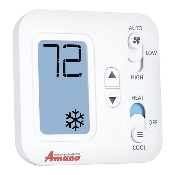
AMANA PHWT-A150H THERMOSTAT
3) SAFETY INFORMATION
• This thermostat is for LOW voltage applications only.
• Turn OFF electricity to all heating and cooling
components.
• All wiring must conform to applicable local
and national building and electrical codes and
ordinances.
4) TO REMOVE EXISTING THERMOSTAT
1. Write down the letters printed near each wire
terminal that is used, and the color of each wire it
is connected to; self-adhesive wire labels are also
enclosed.
2. Carefully remove wires from existing thermostat
and bend so they cannot fall back into wall or
touch each other.
3. Remove existing thermostat base from the wall.
5) TO INSTALL NEW THERMOSTAT
1. Mount the thermostat on an inside wall about
five feet above the floor in an area that has good
circulation, but is not directly affected by a vent
or duct.
2. If painting or construction is still ongoing, cover
the thermostat completely or wait until work is
complete before mounting thermostat.
3. If new mounting holes are needed, mark the
placement of the new mounting holes through
the thermostat base. Using a 3/16" drill bit,
drill the holes you have marked and insert the
supplied wall anchors.
4. Feed the wires through the wire opening in the
base and use supplied screws to mount base to
the wall.
5. Using Section 7) WIRING DIAGRAMS, wire each
terminal on the new thermostat base. Ensure that
the bare end is fully seated into the connector,
then tighten securely. Pull gently on wires to
ensure they are secure.
6. Place thermostat front back onto the base.
7. Restore power back to heating and cooling
components and thermostat.
8. See Section 8) INSTALLER SETTINGS MENU, to
adjust the required settings needed for each
system type.
Advertisement
Table of Contents

Related Manuals for Amana PHWT-A150H


Summary of Contents for Amana PHWT-A150H
- Page 1 1) DESCRIPTION AND COMPATIBILITY five feet above the floor in an area that has good circulation, but is not directly affected by a vent The Amana PHWT-A150H is a non-programmable or duct. electronic thermostat, which can be used with the 2.
- Page 2 6) FRONT PANEL CONTROLS THERMOSTAT BUTTONS: THERMOSTAT SYSTEM MODE SWITCH POSITIONS: HEAT position UP button OFF position DOWN button COOL position HEAT = thermostat permits heating operation UP / DOWN = used for raising or lowering the target set OFF = thermostat stops all heating or cooling functions temperature and selecting user options and settings in COOL = thermostat permits cooling operation the display screen.
- Page 3 7) WIRING DIAGRAMS UP TO 2H/1C HEAT PUMP APPLICATIONS: UP TO 1H/1C CONVENTIONAL APPLICATIONS: (AMANA PTH & HEH PTAC MODELS): (AMANA PTC PTAC MODELS) **see note 1 HP Reversing Valve NOT USED 24V Power 24V Power Heat Pump Compressor A/C Cooling...
- Page 4 8) INSTALLER SETTINGS 17 (Backlight Always On): Allows the display backlight MENU# SETTING OPTIONS to remain on constantly, or turn off automatically after 10 seconds. F, C Scale 18 (Set Temp After Mode Change): Determines if the Temp. Calibration Zero, -5F to +5F thermostat recalls the last used set temperature per (-3C to +3C) mode, or uses a default set temperature when the...
Need help?
Do you have a question about the PHWT-A150H and is the answer not in the manual?
Questions and answers