Table of Contents
Advertisement
Quick Links
Non-Programmable Electronic Thermostat
Electric Heat or HP, Manual Changeover, Hardwired
• Configurable
• 2-Stage Heat Pump Systems
• 1-Stage Electric Heat
• Backlit Display
• Field Calibration Feature
• Relay Outputs
(minimum voltage drop in thermostat)
• Ideally Suited for:
–
Residential (New Construction/Replacement)
–
Light Commercial
Installation, Operation &
Application Guide
www.amana-ptac.com
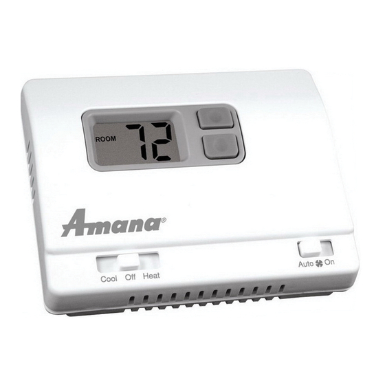
Parts Diagram
Up Button
Down Button
Large Backlit Display
Reset Switch
RESET
Left
Right
Mode Switch
Button
Button
Specifications
Electrical rating: • 24 VAC (18-30 VAC)
• 4 amp maximum total load
• 1 amp maximum per terminal
Temperature control range: 45°F to 90°F (7°C to 32°C) Accuracy: ± 1°F (± 0.5°C)
System configurations: 2-stage heat & 1-stage cool heat pump, 1-stage electric heat
Timing: Anti-short Cycle: 4 minutes
Backlight Operation: 10 seconds
Terminations: R, C, O/B, Y, W, GH, GL
Important Safety Information
WARNING!: Always turn off power at the main power supply before installing, cleaning,
or removing thermostat.
• This thermostat is for 24 VAC applications only; do not use on voltages over 30 VAC
• All wiring must conform to local and national electrical and building codes
• Do not use air conditioning when the outdoor temperature is below 50 degrees; this can damage
your A/C system and cause personal injuries
• Use this thermostat only as described in this manual
Package Contents/Tools Required
Package includes: Amana
®
2246003 thermostat on base, thermostat cover, wiring labels, screws
and wall anchors, Installation, Operation and Application Guide
Tools required for installation: Drill with 3/16" bit, hammer, screwdriver
2246003
LEFT
RIGHT
Fan Switch
To Remove Existing Thermostat
ELECTRICAL SHOCK HAZARD – Turn off power at the main service panel by removing
the fuse or switching the appropriate circuit breaker to the OFF position before
removing the existing thermostat.
1. Turn off power to the heating and cooling system by removing the fuse or switching the
appropriate circuit breaker off.
2. Remove cover of old thermostat. This should expose the wires.
3. Label the existing wires with the enclosed wire labels before removing wires.
4. After labeling wires, remove wires from wire terminals.
5. Remove existing thermostat base from wall.
6. Refer to the following section for instructions on how to install this thermostat.
To Install Thermostat
ELECTRICAL SHOCK HAZARD – Turn off power at the main service panel by removing
the fuse or switching the appropriate circuit breaker to the OFF position before
removing the existing thermostat.
IMPORTANT: Thermostat installation must conform to local and national building and
electrical codes and ordinances.
Note: Mount the thermostat about four feet above the floor. Do not mount the thermostat
on an outside wall, in direct sunlight, behind a door, or in an area affected by a vent
or duct.
1. Turn off power to the heating and cooling system by removing the fuse or switching the appropriate
circuit breaker off.
2. To remove cover, insert and twist a coin or screwdriver in the slots on top of the thermostat.
3. Put thermostat base against the wall where you plan to mount it (Be sure wires will feed through
the wire opening in the base of the thermostat).
4. Mark the placement of the mounting holes.
5. Set thermostat base and cover away from working area.
6. Using a 3/16" drill bit, drill holes in the places you have marked for mounting.
7. Use a hammer to tap supplied anchors in mounting holes.
8. Align thermostat base with mounting holes and feed the control wires through wire opening.
9. Use supplied screws to mount thermostat base to wall.
10. Insert stripped, labeled wires in matching wire terminals. See "Wiring Diagrams" section of this
manual.
CAUTION!: Be sure exposed portion of wires does not touch other wires.
11. Gently tug wire to be sure of proper connection. Double check that each wire is connected to the
proper terminal.
12. Seal hole for wires behind thermostat with non-flammable insulation or putty.
13. Replace cover on thermostat by snapping it in place.
14. Turn on power to the system at the main service panel.
15. Test thermostat operation as described in "Testing the Thermostat".
Terminal Designator Descriptions
R – 24 VAC hot
C – 24 VAC common
O/B – Reversing valve
Y – 1st stage cool, 1st stage HP heat for HP
W – 2nd stage heat for HP, 1st stage electric heat
GH – Fan High
GL – Fan Low
Output Chart
HSo = Heat Pump (cool active reversing valve)
HSb = Heat Pump (heat active reversing valve)
HSE = Electric Heat
Note: GL will be on during heating and cooling cycle when fan switch is set to Auto
Wiring Diagram Conversions
Cool & Electric Heat
X
Former
Compressor
Heat
Fan High
Fan Low
1
Cool
1
Heat
2
Heat
ST
ST
ND
Y, GL, O
Y, GL
Y, GL, W
Y, GL
Y, GL, B
Y, GL, B, W
Y, GL
W, GL
W, GL
Heat Pump
X
Former
Reversing Valve
Compressor
Auxiliary Heat
Fan High
Fan Low
Advertisement
Table of Contents

Related Manuals for Amana 2246003


Summary of Contents for Amana 2246003
-
Page 1: To Remove Existing Thermostat
Wiring Diagram Conversions or removing thermostat. • This thermostat is for 24 VAC applications only; do not use on voltages over 30 VAC Cool & Electric Heat Heat Pump • All wiring must conform to local and national electrical and building codes • Do not use air conditioning when the outdoor temperature is below 50 degrees; this can damage your A/C system and cause personal injuries Former Former • Use this thermostat only as described in this manual Reversing Valve Package Contents/Tools Required Compressor Compressor Package includes: Amana ® 2246003 thermostat on base, thermostat cover, wiring labels, screws Heat Auxiliary Heat and wall anchors, Installation, Operation and Application Guide Tools required for installation: Drill with 3/16” bit, hammer, screwdriver Fan High Fan High Fan Low Fan Low... -
Page 2: Configuration Mode
CAUTION!: Do not energize the air conditioning system when the outdoor temperature is To configure the Amana 2246003 , perform the following steps: ® below 50 degrees. It can result in equipment damage or personal injury. 1. Slide the Mode switch to the OFF position. 2. Remove the cover of the thermostat by gently pulling on one of the corners. Cool Test 3. Simultaneously hold the LEFT & RIGHT buttons in for 2 seconds while the Amana 2246003 is in ® 1. Slide Mode switch to Cool mode. OFF mode. Cool Off Heat 2. Adjust set temperature so it is 5 degrees below room temperature. 4. Press the down or up button to change settings within each screen.
Need help?
Do you have a question about the 2246003 and is the answer not in the manual?
Questions and answers