Samson 3730-0 Mounting And Operating Instructions
Series 3730.
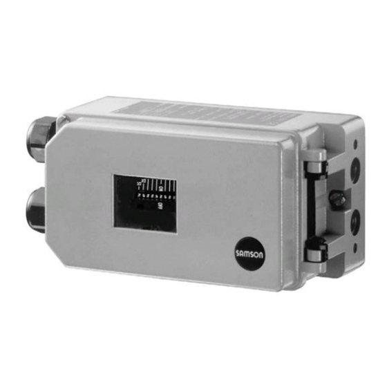
electropneumatic positioner
Hide thumbs
Also See for 3730-0:
- Mounting and operating instructions (64 pages) ,
- Quick manual (2 pages) ,
- Mounting and operating instructions (80 pages)

Related Manuals for Samson 3730-0


Summary of Contents for Samson 3730-0
- Page 1 Series 3730 Electropneumatic Positioner Type 3730-0 Fig. 1 · Type 3730-0 Mounting and Operating Instructions EB 8384-0 EN (1300-1609) Edition November 2010...
- Page 2 Definitions of the signal words used in these instructions DANGER! NOTICE indicates a hazardous situation which, if not indicates a property damage message. avoided, will result in death or serious injury. Note: Supplementary explanations, WARNING! information and tips indicates a hazardous situation which, if not avoided, could result in death or serious injury.
- Page 3 Contents Contents Page Important safety instructions ..... . 4 Article code ......5 Design and principle of operation.
-
Page 4: Important Safety Instructions
Safety instructions Important safety instructions For your own safety, follow these instructions concerning the mounting, start-up and opera- tion of the positioner: The positioner is to be mounted, started up or operated only by trained and experienced personnel familiar with the product. According to these Mounting and Operating Instructions, trained personnel refers to indi- viduals who are able to judge the work they are assigned to and recognize possible dan- gers due to their specialized training, their knowledge and experience as well as their... -
Page 5: Article Code
Article code Article code Article code Type 3730-0 x 0 0 0 0 0 0 0 0 x 0 0 x 0 x x Explosion protection Without ATEX: II 2G Ex ia IIC T6, II 2D Ex tb IIIC T 80 °C IP 66 FM/CSA: Class I, Zone 0 AEx ia IIC;... -
Page 6: Design And Principle Of Operation
Design and principle of operation Design principle (9) with fixed settings is used to purge the positioner and also guarantees trouble-free operation operation of the pneumatic booster. The output signal pressure supplied by the The electropneumatic positioner is mounted booster can be limited over the DIP switch to pneumatic control valves and is used to assign the valve position (controlled vari- able x) to the control signal (reference vari-... -
Page 7: Technical Data
Design and principle of operation Control valve Travel sensor PD controller DIP switches i/p converter Air capacity booster Pressure regulator Flow regulator 10 Volume restriction Fig. 2 · Functional diagram Technical data Positioner (technical data in test certificates additionally apply for explosion-protected devices) Nominal travel, Direct attachment to Type 3277: 5.3 to 30 mm, adjustable... - Page 8 Design and principle of operation Positioner (technical data in test certificates additionally apply for explosion-protected devices) Version without explosion protection: £ 6 V (corresponding to 300 W at 20 mA), Load impedance explosion-protected version: £ 6 V Supply air Supply pressure 1.4 to 7 bar (20 to 105 psi) Air quality acc.
-
Page 9: Attachment To The Control Valve – Mounting Parts And Accessories
– Mounting parts and accessories The positioner can be attached either di- rectly to a SAMSON Type 3277 Actuator or according to IEC 60534-6 (NAMUR) to con- trol valves with cast yokes or rod-type yoke. For attachment to the various actuators, cor- responding mounting parts and accessories Fig. - Page 10 3277-5 25.0 3277 120/240/350 35.0 Actuators 355/700 10.0 50.0 Travel table for attachment according to IEC 60534-6 (NAMUR) SAMSON valves Other valves/actuators Required Assigned lever pin position cm² Rated travel mm Min. Travel Max. 60 and 120 with 18.0...
- Page 11 Attachment to the control valve – Mounting parts and accessories Table 2 Direct attachment to Type 3277 Actuator Mounting parts for actuators with 240, 350, 355 and 700 cm², see Fig. 5 1400-7453 cm² Steel Stainl. steel Required piping with screw fittings for "Actuator 1400-6444 1400-6445 stem retracts"...
-
Page 12: Direct Attachment
Attachment to the control valve – Mounting parts and accessories Direct attachment pointing towards the signal pressure connection. Make sure that the bonded 4.1.1 Type 3277-5 Actuator gasket (14) points towards the actuator yoke. Refer to Table 1 on page 10 for the required 5. - Page 13 Attachment to the control valve – Mounting parts and accessories Lever Symbols Switchover plate (9) Disk spring Actuator stem Follower pin extends Follower clamp Screw plug Left attachment Right attachment Stopper Connecting plate Actuator stem retracts Seal rings Pressure gauge bracket Press.
-
Page 14: Type 3277 Actuator
Attachment to the control valve – Mounting parts and accessories 4.1.2 Type 3277 Actuator (3). Adjust the lever (1) correspondingly and open the positioner cover to hold Refer to Table 2 on page 11 for the required the positioner shaft in position at the cap mounting parts and the accessories with or the switch. - Page 15 Attachment to the control valve – Mounting parts and accessories Lever Connection block 12.1 Screw Disk spring 12.2 Stopper or connection for 10 14 external piping Follower pin Switch plate Follower clamp 11 11.1 Gasket Cover plate Formed seal Cover Gasket 11.1 Vent plug Lever M...
-
Page 16: Attachment According To Iec 60534-6
Attachment to the control valve – Mounting parts and accessories Attachment according to (8) on the positioner, making sure both IEC 60534-6 seal rings (6.1) are seated properly. 4. Select required lever size (1) M, L or XL The positioner is attached to the control and pin position according to the actua- valve with a NAMUR bracket (10). - Page 17 Attachment to the control valve – Mounting parts and accessories Attachment to rod-type yoke Rods with 20 to 35 mm diameter Attachment to NAMUR rib Additional bracket for actuators with 2800 cm and travel ³ 60 mm Lever Lever XL and L Disk spring Follower pin 14.1...
-
Page 18: Reversing Amplifier For Double-Acting Actuators
5. Use a screwdriver (8 mm wide) to screw positioner must be fitted with a reversing the enclosed filters (1.6) into the con- amplifier, e.g. the SAMSON Type 3710 Re- necting boreholes A and Z. versing Amplifier (see Mounting and Oper- ating Instructions EB 8392 EN). - Page 19 Attachment to the control valve – Mounting parts and accessories From the positioner Output 38 Supply 9 Control signals to the actuator Reversing amplifier Connecting plate 6.1 O-rings 1.1 Special screws 1.2 Gasket 6.2 Screws 1.3 Special nuts 1.4 Rubber seal 1.5 Sealing plug 1.6 Filter Fig.
-
Page 20: Attachment To Type 3510 Micro-Flow Valve
Attachment to the control valve – Mounting parts and accessories Attachment to Type 3510 Micro-flow Valve The positioner is attached to the valve yoke using a bracket. Refer to Table 3 on page 11 for the required mounting parts and the accessories with their order numbers as well as to the travel table on page 10! 1. - Page 21 Attachment to the control valve – Mounting parts and accessories Lever Disk spring Follower pin Clamp Connecting plate Seal rings Pressure gauge bracket Pressure gauge mounting kit Bracket Screw Note: Always use the connecting plate (6) included in the accessories to connect supply and output.
-
Page 22: Attaching Positioners With Stainless Steel Housings
Attachment to the control valve – Mounting parts and accessories Attaching positioners with Air purging function for stainless steel housings single-acting actuators Positioners with stainless steel housings re- The exhaust air from the positioner is di- quire mounting parts that are completely verted to the actuator spring chamber to made of stainless steel or free of aluminum. -
Page 23: Connections
Connections Connections Threaded bushing G ¼ 0310-2619 (M20 x 1.5): ¼ NPT 0310-2550 WARNING! Mount the positioner, keeping the following NOTICE sequence: The adapter uses one of the M20 x 1.5 con- 1. Remove the protective film from the nections in the housing which means just pneumatic connections one cable gland can be installed. -
Page 24: Signal Pressure Gauges
Connections Actuator stem retracts FE (Air to close ATC) ally designed as a bore with ¼ NPT or G ¼ thread. Fail-safe position "Valve OPEN" The customary fittings for metal and copper (for globe and angle valves): pipes or plastic hoses can be used. For tight-closing valves, the maximum signal If the positioner is attached directly to the pressure pst... -
Page 25: Electrical Connections
Connections Electrical connections In particular, the radial thickness of the con- ductor insulation for common insulation ma- terials, such as polyethylene, must have a DANGER! minimum radial thickness of 0.2 mm. Risk of electric shock and/or The diameter of an individual wire in a the formation of an explosive fine-stranded conductor must not be smaller atmosphere! - Page 26 Connections Accessories: Plastic cable gland M20x1.5: – Black Order no. 8808-1011 – Blue Order no. 8808-1012 – Ni-plated brass Order no. 1890-4875 – Stainless steel 1.4305 Input Order no. 8808-0160 control signal Adapter M20 x 1.5 to ½ NPT: – Aluminum, powder-coated Order no.
-
Page 27: Operation
Operation Operation ZERO and SPAN adjusters The ZERO and SPAN potentiometers are Operator controls used to adjust the starting point (zero) and the upper range value (span) of the refer- DIP switches S1 to S10 ence variable. The positioner is mainly operated via the DIP Volume restriction Q switches, which allow you to set the most im- The volume restriction is used to adapt the... -
Page 28: Start-Up And Settings
To determine the switch position, read the at the actuator in SAMSON actuators: associated switch position S1 = ON or OFF The “SIDE“ position applies for actuators from the cover plate at the actuator symbols. -
Page 29: Presetting The Travel
Start-up and settings Presetting the travel Reference variable At switches S2 and S3, select the travel that Use switches S7 and S8 to determine the in- comes closest to the rated valve travel, tak- put signal, i.e. the range of the reference ing into account the pin position. -
Page 30: Connecting The Positioner
Start-up and settings Connecting the positioner 7.10 Gain factor Apply the supply air to the pneumatic con- Move the valve in small steps. If the valve tends to hunt, set switch S6 to ON to re- nection (Supply 9). Make sure to use the ap- propriate pressure as specified in section duce the gain of the control loop. -
Page 31: Maintenance
Maintenance Maintenance Servicing explosion-protected devices The positioner does not require any mainte- nance. If a part of the device on which the explo- sion protection is based needs to be ser- There are filters with a 100 mm mesh size in viced, the device must not be put back into the pneumatic connections for supply and operation until a qualified inspector has as-... -
Page 32: Dimensions In Mm
Dimensions in mm Dimensions in mm Direct attachment M20 x 1.5 Type 3710 Reversing Amplifier (option) Output (38) Supply (9) Pressure gauge bracket or connecting plate Attachment acc. to IEC 60534-5 (NAMUR) Reversing amplifier Lever mm (1079-1118 or 1079-1119) S = 17 (option) M = 50 Output (A... - Page 33 Dimensions in mm Output Y Output Y Supply (9) Output Y Output Y Type 3710 Reversing Amplifier (optional) EB 8384-0 EN...
- Page 34 EB 8384-0 EN...
- Page 35 EB 8384-0 EN...
- Page 36 EB 8384-0 EN...
- Page 37 EB 8384-0 EN...
- Page 38 EB 8384-0 EN...
- Page 39 EB 8384-0 EN...
- Page 40 EB 8384-0 EN...
- Page 41 EB 8384-0 EN...
- Page 42 EB 8384-0 EN...
- Page 43 EB 8384-0 EN...
- Page 44 SAMSON AG · MESS- UND REGELTECHNIK Weismüllerstraße 3 · 60314 Frankfurt am Main · Germany Phone: +49 69 4009-0 · Fax: +49 69 4009-1507 EB 8384-0 EN Internet: http://www.samson.de...
Need help?
Do you have a question about the 3730-0 and is the answer not in the manual?
Questions and answers