Samson 3730-5 Mounting And Operating Instructions
3730 series
electropneumatic positioner
with foundation fieldbus communication
Hide thumbs
Also See for 3730-5:
- Quick start manual ,
- Mounting and operating instructions (208 pages) ,
- Configuration manual (136 pages)
Table of Contents

Related Manuals for Samson 3730-5


Summary of Contents for Samson 3730-5
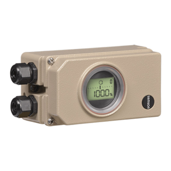
- Page 1 Series 3730 Electropneumatic Positioner Type 3730-5 with F fieldbus communication OUNDATION™ FF Device Rev 2 Fig. 1 · Type 3730-5 Mounting and Operating Instructions EB 8384-5 EN (1300-1619) Firmware version 1.55 Edition July 2012...
-
Page 2: Table Of Contents
Contents Contents Page Important safety instructions ..... . 8 Article code ......10 Design and principle of operation . - Page 3 Contents Defining the valve closed position ....52 Setting the volume restriction Q ....53 Adapting the display.
- Page 4 Definitions of the signal words used in these instructions DANGER! NOTICE indicates a hazardous situation which, if not indicates a property damage message. avoided, will result in death or serious injury. Note: Supplementary explanations, information and tips WARNING! indicates a hazardous situation which, if not avoided, could result in death or serious inju- EB 8384-5 EN...
- Page 5 Revisions of the positioner firmware Revisions of the positioner firmware compared to the previous version – Control R Control R 1.43 R 1.44 Internal revisions R 1.45 Internal revisions R 1.46 Internal revisions R 1.52 Application type The user determines in the positioner whether the valve is to oper- ate as a control valve or an open/close (on/off valve) (see section 3.1) Diagnosis...
- Page 6 Revisions of the positioner firmware Revisions of the positioner firmware compared to the previous version – Control R Codes 48 extended The following subitems have been added to Code 48: h0: Activation/deactivation reference test h1: Reference test completed (YES/No) h3: Automatic reset of diagnosis after this time h4: Remaining time until diagnosis time See section 14.
- Page 7 You can find additional information on the enclosed CD-ROM (CD 8384-5) or on the Internet at http://www.samson.de. The CD-ROM (CD 8384-5) contains further information on the Type 3730-5 Positioner: [Documentation] – KH 8384-5 EN: Configuration Manual for Type 3730-5 Electropneumatic Positioner, configuration and operation over F ™...
-
Page 8: Important Safety Instructions
Important safety instructions Important safety instructions For your own safety, follow these instructions concerning the mounting, start-up and opera- tion of the positioner: The positioner is to be mounted, started up or operated only by trained and experienced personnel familiar with the product. According to these Mounting and Operating Instructions, trained personnel refers to individuals who are able to judge the work they are assigned to and recognize possible dangers due to their specialized training, their knowledge and experience as... - Page 9 Important safety instructions Note: The device with a CE marking fulfills the requirements of the Directives 94/9/EC (ATEX) and 89/336/EEC (EMC). The Declaration of Conformity is included on the CD-ROM (CD 8384-5). EB 8384-5 EN...
-
Page 10: Article Code
Article code Article code Positioner Type 3730-5 x x x 0 x 0 x x 0 x 0 0 x 0 x x With LCD and autotune, F ™ fieldbus OUNDATION Explosion protection Without ATEX: II 2G Ex ia IIC T6; II 2D Ex tb IIIC T 80°C IP 66 FM/CSA: Class I, Zone 0 AEx ia IIC;... -
Page 11: Design And Principle Of Operation
Design and principle of operation Design principle When a deviation occurs, the actuator is pressurized or vented. If required, the operation changes in the signal pressure can be slowed down by a connectable Q restriction. The electropneumatic positioner is attached The signal pressure supplied to the actuator to pneumatic control valves. -
Page 12: Application Type
The positioner follows the reference Direct attachment to SAMSON variable given over local operation. Type 3277 Actuator: Section 4.1 Attachment to actuators acc. to IEC 60534-6 (NAMUR): Section 4.2... -
Page 13: Communication
Design and principle of operation positioner can no longer operate and the Note: The binary inputs are configured in control valve moves to the fail-safe position the DI Function Blocks (see Configuration determined by the actuator, independent of Manual KH 8384-5 EN). the reference variable. -
Page 14: Configuration Using Trovis-View Software
SAMSON devices. The software together with a device-specific module allow the con- figuration and parameterization of the de- vice. The device-specific module for Type 3730-5 can be downloaded free of charge from the SAMSON website (Services > Software > TROVIS-VIEW). -
Page 15: Technical Data
Design and principle of operation Technical data Type 3730-5 Positioner (technical data in test certificates additionally apply for explosion-protected devices) Direct attachment to Type 3277: 3.6 to 30 mm Rated travel, Attachment acc. to IEC 60534-6: 3.6 to 200 mm adjustable Attachment to rotary actuators (VDI/VDE 3845): 24°... - Page 16 Design and principle of operation Type 3730-5 Positioner (technical data in test certificates additionally apply for explosion-protected devices) –20 to +80 °C for all versions Permissible ambient –45 to +80 °C with metal cable gland temperature –25 to +80 °C with inductive limit switch (SJ2-S1N) and metal cable gland The limits in test certificate additionally apply for explosion-protected devices.
- Page 17 Design and principle of operation Options for Type 3730-5 Binary input BE2 for floating contact R < 100 W, contact loadability 100 mA, static destruction limit 20 V / 5.8 mA, Switching input galvanically isolated Solenoid valve Approval acc. to IEC 61508/SIL...
-
Page 18: Attachment To The Control Valve - Mounting Parts And Accessories
The positioner is standard equipped with the lever M (pin position 35). The positioner is suitable for the following types of attachment: Direct attachment to SAMSON Type 3277 Actuator Attachment to actuators according to IEC 60534-6 (NAMUR) Attachment to Type 3510 Micro-flow... - Page 19 [cm²] [mm] Min. Travel Max. 25.0 120/240/350 35.0 355/700 10.0 50.0 Attachment according to IEC 60534-6 (NAMUR) SAMSON valves/Type 3271 Actuator Other valves/actuators Required Assigned Actuator size Rated travel lever pin position [cm²] [mm] min. Travel max. 60 and 120 with 18.0...
-
Page 20: Direct Attachment
Attachment to the control valve – Mounting parts and accessories Direct attachment ing towards the signal pressure connec- tion. Make sure that the bonded gasket 4.1.1 Type 3277-5 Actuator (14) points towards the actuator yoke. 5. 15 mm travel: Keep the follower pin (2) Refer to Table 1 on page 41 for the required at lever M (1) on the back of the mounting parts as well as the accessories... - Page 21 Attachment to the control valve – Mounting parts and accessories Symbols Lever Switchover plate (9) 1.1 Nut Actuator stem 1.2 Disk spring extends Follower pin Follower clamp Vent plug Attachment left Attachment right Stopper Connecting plate Actuator stem 6.1 Seal rings retracts Pressure gauge bracket Press.
-
Page 22: Type 3277 Actuator
Attachment to the control valve – Mounting parts and accessories 4.1.2 Type 3277 Actuator (3). Adjust the lever (1) correspondingly and open the positioner cover to hold Refer to Table 2 on page 41 or the required the positioner shaft in position at the cap mounting parts as well as the accessories or the switch (Fig. - Page 23 Attachment to the control valve – Mounting parts and accessories Lever Connection block 12.1 Screw Disk spring 12.2 Stopper or connection for external piping Follower pin Switch plate Follower clamp 10 14 Gasket Cover plate Formed seal Cover 11 11.1 Gasket 11.1 Vent plug Lever M...
-
Page 24: Attachment According To Iec 60534-6
Attachment to the control valve – Mounting parts and accessories Attachment according to 3. Mount connecting plate (6) or pressure IEC 60534-6 gauge bracket (7) with pressure gauges (8) on the positioner, making sure both Refer to Table 3 on page 42 for the required seal rings (6.1) are seated properly. - Page 25 Attachment to the control valve – Mounting parts and accessories Attachment to rod-type yoke Rod diameter 20 to 35 mm Attachment to NAMUR rib Additional bracket for actuators with 2800 cm and travel ³ 60 mm Lever Lever XL and L 14.1 Disk spring Follower pin...
-
Page 26: Attachment To Type 3510 Micro-Flow Valve
Attachment to the control valve – Mounting parts and accessories Attachment to Type 3510 Micro-flow Valve Refer to Table 3 on page 42 for the required mounting parts as well as the accessories with their order numbers. Note the travel table on page 19! The positioner is attached to the valve yoke using a bracket. - Page 27 Attachment to the control valve – Mounting parts and accessories Lever Disk spring Follower pin Clamp Connecting clamp Seal rings Pressure gauge bracket Pressure gauge mounting kit Bracket Screw Note: Always use the connecting plate (6) included in the accessories to connect supply and output.
-
Page 28: Attachment To Rotary Actuators
90°. Prior to attaching the positioner to the 7. Place positioner on the top pair of SAMSON Type 3278 Rotary Actuator, mount the associated adapter (5) to the free brackets (10) and screw tight. Con- end of the rotary actuator shaft. - Page 29 Attachment to the control valve – Mounting parts and accessories (7, 8) 10.1 80 mm Note: Always use the connecting plate (6) included in the accessories to connect 130 mm supply and output. Never screw threaded parts directly into the Slot housing.
-
Page 30: Heavy-Duty Version
(11) underneath, if der no.1400-6964) into the signal pres- necessary. sure output of the positioner (or the out- 2. For SAMSON Type 3278 and VETEC put of the pressure gauge bracket or S160 Rotary Actuator, screw the adapter connecting plate). - Page 31 Actuator shaft or adapter 5.1 Adapter 10.1 10.1 Attachment acc. to VDE/VDI 3845 (2010) level 1, size AA1 to AA4, section 15.1 SAMSON Type 3278 VETEC S160, VETEC R Fig. 11 · Attachment to rotary actuators (heavy-duty version) EB 8384-5 EN...
-
Page 32: Reversing Amplifier For Double-Acting Actuators
5. Use a screwdriver (8 mm wide) to screw positioner must be fitted with a reversing the enclosed filters (1.6) into the con- amplifier, e.g. the SAMSON Type 3710 Re- necting boreholes A and Z. versing Amplifier (see Mounting and Oper- ating Instructions EB 8392 EN). - Page 33 Attachment to the control valve – Mounting parts and accessories From the positioner Output 38 Supply 9 Control signals to the actuator Connecting plate Reversing amplifier 1.1 Special screws 6.1 O-rings 1.2 Gasket 6.2 Screws 1.3 Special nuts 1.4 Rubber seal 1.5 Sealing plug 1.6 Filter Fig.
-
Page 34: Attaching An External Position Sensor
Attachment to the control valve – Mounting parts and accessories Attaching an external Operation and setting are described in sections 7 and 8. position sensor – Since 2009, the back of the position sen- sor (20) is fitted with two pins acting as Refer to Table 6 on page 43 for the mount- mechanical stops for the lever (1). - Page 35 Attachment to the control valve – Mounting parts and accessories version "Actuator stem extends". pin (2) from the travel table on page 19. For the fail-safe position "Actuator stem re- The positioner is delivered with lever M tracts" the connection on the top diaphragm in pin position 35 on the sensor.
-
Page 36: Mounting The Position Sensor With Attachment According To Iec 60534-6
Attachment to the control valve – Mounting parts and accessories of the follower clamp (3). It must rest on Unthread the nut (1.1) and remove the it with spring force. lever together with the disk spring (1.2) Screw tight the mounting plate (21) onto from the sensor shaft. -
Page 37: Mounting The Position Sensor To Type 3510 Micro-Flow Valve
Attachment to the control valve – Mounting parts and accessories the follower plate (3) and fix with the 2. Screw the position sensor (20) onto the bracket (21). screws (14.1). 3. Select the lever S (1) from the accesso- 5. Place the bracket with the sensor at the NAMUR rib in such a manner that the ries and screw the follower pin (2) into follower pin (2) rests in the slot of the fol-... -
Page 38: Mounting The Position Sensor To Rotary Actuators
Attachment to the control valve – Mounting parts and accessories 4.6.4 Mounting the position 4. Place the lever (1) and disk spring (1.2) sensor to rotary actuators on the sensor shaft. Place the lever (1) in mid-position and For the required mounting parts and the ac- hold it in place. -
Page 39: Attaching Positioners With Stainless Steel Housings
Attachment to the control valve – Mounting parts and accessories Attaching positioners with Air purging function for stainless steel housings single-acting actuators Positioners with stainless steel housings re- The exhaust air from the positioner is di- quire mounting parts that are completely verted to the actuator spring chamber to made of stainless steel or free of aluminum. - Page 40 Attachment to the control valve – Mounting parts and accessories over piping. An adapter available as an ac- cessory is used for this purpose: Threaded bushing G ¼ 0310-2619 (M20 x 1.5): ¼ NPT 0310-2550 NOTICE The adapter uses one of the M20 x 1.5 con- nections in the housing which means just one cable gland can be installed.
-
Page 41: Mounting Parts And Accessories
Attachment to the control valve – Mounting parts and accessories Mounting parts and accessories Order no. Table 1 · Direct attachment to Type 3277-5 Actuator (Fig. 4) Mounting parts Mounting parts for actuators 120 cm² or smaller 1400-7452 Switchover plate (old) for Actuator Type 3277-5xxxxxx.00 (old) 1400-6819 Switchover plate new for Actuator Type 3277-5xxxxxx.01 (new) 1400-6822... - Page 42 1400-9526 parts Attachment for SAMSON Type 3278 with 160/320 cm², CrNiMo steel bracket 1400-7614 Attachment for SAMSON Type 3278 with 160 cm² and for VETEC Type S160, Type R 1400-9245 and Type M, heavy-duty version 1400-5891 Attachment for SAMSON Type 3278 with 320 cm² and for VETEC Type S320,...
- Page 43 1400-9992 rotary actuators Bracket surface corresponds to level 2, heavy-duty version 1400-9974 SAMSON Type 3278 with 160 cm² (also for VETEC Type S160 and Type R), 1400-9385 heavy-duty version 1400-5891 SAMSON Type 3278 with 320 cm² and for VETEC Type S320, heavy-duty...
-
Page 44: Connections
Connections Connections observed. Blow through all air pipes and hoses tho- roughly prior to connecting them. WARNING! Mount the positioner, keeping the following sequence: If the positioner is attached directly to the 1. Remove protective film from pneumatic Type 3277 Actuator, the connection of the connections. -
Page 45: Signal Pressure (Output)
Connections Actuator stem retracts FE (AIR TO CLOSE) Electrical connections Fail-safe position "Valve Open" (for globe and angle valves): DANGER! For tight-closing valves, the maximum signal Risk of electric shock and/or pressure pst is roughly estimated as fol- the formation of an explosive lows: atmosphere! –... - Page 46 Connections Selecting cables and wires: Cable entries To install and select cables and wires as well The cable entry with M20 x 1.5 cable gland, as to run several intrinsically safe circuits in 6 to 12 mm clamping range. one multi-core cable, observe the installation There is a second M20 x 1.5 threaded bore regulations valid in the country of use.
- Page 47 Connections Limit switch The positioner can report the switching state over the bus protocol. For operation of the limit switches, switching amplifiers have to be connected in the out- Solenoid valve (forced venting function) put circuit. Their function is to control the limit values of the control circuit according to For positioners fitted with the optional sole- EN 60947-5-6, thus ensuring operational...
-
Page 48: Establishing Communication
Connections 5.2.1 Establishing communication The communication structure between the controller, logic solvers (PLC) or automation system, or between a PC or work station and the positioner(s) is implemented to con- form with IEC 61158-2. EB 8384-5 EN... - Page 49 Connections Power conditioner Power Conditioner Power supply unit Speisegerät Control system Leitsystem EN 61158-2 fieldbus OUNDATIONTM Bus termination Terminierung EN 61158-2 fieldbus OUNDATIONTM 3730-50 3730-50 3730-50 3730-50 Power conditioner Power Conditioner Power supply unit Control system Speisegerät Leitsystem fieldbus OUNDATIONTM Ex fieldbus barrier/isolator EN 61158-2 Ex-Feldbusbarriere/Trenner...
-
Page 50: Operator Controls And Readings
Operator controls and readings Operator controls and Readings on display readings Icons appear on the display that are as- signed to parameters, codes and functions. Rotary pushbutton Operating modes: The rotary pushbutton is located underneath Manual mode (MAN), section 8.2.1 the front protective cover. - Page 51 Operator controls and readings Displays and their meaning AUtO Automatic mode Reset together Clockwise Start AO Transducer Block is in the MAN mode. Refer to KH 8384-5 EN. SAFE Counterclockwise Fail-safe position blinking Emergency mode Error Substitute calibration (see error code 62 on page 91) Escape TunE Initialization in progress...
-
Page 52: Start-Up - Settings
Start-up – Settings Start-up – Settings NOTICE Perform the start-up settings in the same se- WARNING! quence as listed (section 7.1 to section 7.6). Mount the positioner, keeping the following sequence: Note: The positioner performs a test in the 1. Remove protective film from pneumatic start-up phase while following its automa- connections. -
Page 53: Setting The Volume Restriction Q
(MAX). The position of volume restriction Q also de- pends on how the signal pressure is routed Reading direction for left at the actuator in SAMSON actuators: attachment of pneumatic connections The “SIDE“ position applies for actuators with a loading pressure connection at the side, e.g. -
Page 54: Limiting The Signal Pressure
Start-up – Settings ® Code 2 Turn Turn until the required pressure limit (1.4/2.4/3.7 bar) appears. ® Code 2 blinks. Press Press to confirm the pressure limit set- Turn ® Required direction ting. Press to confirm reading direction. Checking the operating Limiting the signal pressure range of the positioner If the maximum actuator force may cause... -
Page 55: Initialization
Start-up – Settings Initialization Turn until the pressure in the positioner builds up, and the control valve moves to its final positions so that the travel/angle of ro- WARNING! tation can be checked. During initialization, the control valve moves The angle of rotation on the back of the through its entire travel/angle of rotation positioner is indicated. - Page 56 Start-up – Settings NOM nominal range The time required for an initialization pro- Initialization mode for all globe valves cess depends on the transit time of the actu- (see section 7.6.2) ator and take several minutes. After a suc- MAN manually selected range cessful initialization, the positioner runs in Initialization mode for globe valves with closed-loop operation indicated by...
-
Page 57: Max - Initialization Based On Maximum Range
Start-up – Settings ® Code 3 , display: No The tight-closing function is activated. Turn ® Code 3 blinks Press NOTICE Turn ® YES Set Code 15 (final position w>) to 99 % for Press , display three-way valves. Select the initialization mode: Canceling an initalization process The initialization procedure can be canceled Initialization mode... -
Page 58: Nom - Initialization Based On Nominal Range
Start-up – Settings Enter the pin position: Enable configuration: Note: If no settings are entered within 120 seconds, the enabled configuration Pin position Default No function becomes invalid. Turn ® Code 4 , Code 4 blinks Press Default No Turn ®... -
Page 59: Man - Initialization Based On A Manually Selected Range
Start-up – Settings (Code 8 ) and travel/angle range end Turn ® Nominal travel/angle (Code 9 ). Press Enable configuration: Select the initialization mode: Note: If no settings are entered within 120 seconds, the enabled configuration Initialization mode function becomes invalid. Default MAX ®... -
Page 60: Sub Substitute Calibration
Start-up – Settings Select the initialization mode: 7.6.4 SUb substitute calibration A complete initialization procedure takes several minutes and requires the valve to Initialization mode move through its entire travel range several Default MAX times. This initialization mode, however, is an emergency mode, in which the control parameters are estimated and not deter- Turn... - Page 61 Start-up – Settings Select the initialization mode: Default No Initialization mode Default MAX Turn ® Code 3 , display: No Press , Code 3 blinks Turn ® Code 6 ® YES Turn , Code 6 blinks Press Press , display ®...
- Page 62 Start-up – Settings Change pressure limit and control parame- Enter closing direction and blocking posi- ters: tion: Closing direction Note: Do not change the pressure limit Direction of rotation caus- (Code 16). Only change the control param- ing the valve to move to the CLOSED position (view eters K (Code 17) and T...
-
Page 63: Zero Calibration
Start-up – Settings Start initialization: Note: If the positioner shows a tendency to oscillate in automatic operating mode, the Press INIT key! parameters K and T must be slightly cor- The positioner switches to MAN mode. rected. Proceed as follows: The blocking position is indicated. -
Page 64: Selecting The Application Type
Start-up – Settings Perform zero calibration: Note: Control over F fieldbus OUNDATION™ is performed over the AO Function Block (control valve) and over the DO1 Function Initialization mode Block (on/off valve). Refer to Configuration Default MAX Manual KH 8384-5 EN. Turn ®... -
Page 65: Operation
Operation Operation You can now configure codes one after the other: Turn and select the required code. WARNING! The actuator stem moves while the positioner Press to access the selected code. The is being operated. code number starts to blink. Do not touch the actuator stem or obstruct it Turn and select the setting. -
Page 66: Operating Modes
Operation Operating modes Adjust the manual reference variable 8.2.1 Automatic and manual modes After initialization has been completed suc- cessfully, the positioner is in automatic Turn ® Code 1 mode (AUTO). , Code 1 blinks. Press Turn until sufficient pressure has been Automatic mode built up in the positioner and the control valve moves to the required position. -
Page 67: Safe - Fail-Safe Position
Operation 8.2.2 SAFE – Fail-safe position Malfunction/maintenance alarm If you want to move the valve to fail-safe po- sition determined during start-up (see sec- All status and fault alarms are assigned to a tion 7.1), proceed as follows: classified status in the positioner. The default settings of the status classification are listed in the code list. -
Page 68: Confirming Error Messages
Operation faster rate than expected. Maintenance is necessary in the short term. Example Outside of specifications Error caused by pin position The positioner is being operated outside the specified conditions of use. Function check Test or calibration procedures are being Fault alarm output performed. -
Page 69: Adjusting The Limit Switch
Adjusting the limit switch Adjusting the limit switch The desired switching function, i.e. whether the output relay shall be picked up or re- The positioner version with an inductive limit leased when the tag has entered the field, switch has one adjustable tag (1) mounted has to be determined, if necessary, at the on the shaft which operates the proximity switching amplifier. - Page 70 Adjusting the limit switch For CLOSED position: 1. Initialize positioner. 2. Use the MAN function to move the positioner to 5 % (see LC display). 3. Adjust the tag using the yellow adjust- ment screw (2) until the tag enters or leaves the field and the switching ampli- fier responds.
-
Page 71: Retrofitting An Inductive Limit Switch
Adjusting the limit switch Retrofitting an inductive limit switch Required retrofit kit: Limit switch Order no. 1400-7460 Note! For explosion-protected devices, the requirements in section 11 need to be kept. 1. Take off the rotary pushbutton (3) and cap (1), unthread the five fixing screws (2) and lift off the plastic cover (9) to- gether with the display, taking care not to damage the ribbon cable (between... -
Page 72: Maintenance
When updates are performed by a service operation until a qualified inspector has as- employee appointed by SAMSON, the up- sessed it according to explosion protection date is confirmed on the positioner by the requirements, has issued an inspection cer- test mark assigned by SAMSON’s Quality... -
Page 73: Maintenance, Calibration And Work On Equipment
Maintenance, calibration and work on equipment a) Updates outside the hazardous area: Remove the positioners from the plant and update them outside the hazardous area. b.) Updates on site: Updates on site are only permitted after the plant operator has presented a sig- ned hot work permit. -
Page 74: Code List
Code list Code list Parameter – Display, values Code Description [default setting] Note: Codes with marked with an asterisk (*) must be enabled with Code 3 prior to configuration. Operating mode Switchover from automatic to manual mode is smooth. In fail-safe mode, the symbol S appears on the display. [MAN] Manual mode In MAN and AUtO mode, the system deviation is represented by AUtO... - Page 75 Code list Parameter – Display, values Code Description [default setting] Note: Codes with marked with an asterisk (*) must be enabled with Code 3 prior to configuration. Nominal range For initialization using NOM or SUb, the nominal travel/angle of rotation of the valve must be entered. mm or angle °...
- Page 76 Code list Parameter – Display, values Code Description [default setting] Note: Codes with marked with an asterisk (*) must be enabled with Code 3 prior to configuration. Travel/angle range end Upper range value for the travel/angle of rotation in the nominal (upper x-range value) or operating range.
- Page 77 Code list Parameter – Display, values Code Description [default setting] Note: Codes with marked with an asterisk (*) must be enabled with Code 3 prior to configuration. Reference variable range If w approaches the percentage adjusted at the final value that end (w-end) causes the valve to open, the actuator is immediately completely filled with air (with AIR TO OPEN) or vented (with AIR TO...
- Page 78 0 to 9 [0] Linear Equal percentage Reverse equal percentage SAMSON butterfly valve linear SAMSON butterfly valve equal percentage VETEC rotary plug valve linear VETEC rotary plug valve equal percentage Segmented ball valve linear Segmented ball valve equal percentage User-defined (defined over operating software) Note: The various characteristics are listed in the Appendix (section 16).
- Page 79 Code list Parameter – Display, values Code Description [default setting] Note: Codes with marked with an asterisk (*) must be enabled with Code 3 prior to configuration. Total valve travel Totaled double valve travel. 0 to 99 · 10 Can be reset to 0 by RES . Exponential reading from 9999 travel Note: The total valve travel is saved in a non-volatile memory cycles onwards...
- Page 80 Code list Parameter – Display, values Code Description [default setting] Note: Codes with marked with an asterisk (*) must be enabled with Code 3 prior to configuration. Auto-w/manual-w info Read only, Auto mode: indicates the supplied automatic reference variable 0.0 to 100.0 % of the span Man mode: indicates the supplied manual reference variable Firmware info control Read only,...
- Page 81 Code list Parameter – Display, values Code Description [default setting] Note: Codes with marked with an asterisk (*) must be enabled with Code 3 prior to configuration. d3 Number of zero The number of zero calibrations since the last initialization. calibrations d4 Number of initializations The number of initializations that have been performed.
- Page 82 Code list Parameter – Display, values Code Description [default setting] Note: Codes with marked with an asterisk (*) must be enabled with Code 3 prior to configuration. A2 CAS_IN value Display of the analog reference variable adopted from an upstream function block A3 CAS_IN status and its status.
- Page 83 Code list Parameter – Display, values Code Description [default setting] Note: Codes with marked with an asterisk (*) must be enabled with Code 3 prior to configuration. t6 Block error DI1 TRD Displays the current block error t7 Target Mode DI2 TRD Required operating mode.
- Page 84 Code list Parameter – Display, values Code Description [default setting] Note: Codes with marked with an asterisk (*) must be enabled with Code 3 prior to configuration. Partial stroke test (PST)/Full stroke test (FST) · Application type Partial stroke test (PST) A0 Start Partial Stroke Test Operating mode and PST testing mode must be set to MAN.
- Page 85 Code list Parameter – Display, values Code Description [default setting] Note: Codes with marked with an asterisk (*) must be enabled with Code 3 prior to configuration. A8 Activation delta y-moni- Activates/deactivates delta y-monitoring toring [No] · YES · ESC A9 delta y-monitoring value The percentage [%] of the entire range of the control pulse be- tween 1 and 10000 1/s (Example: 10 % = 10000 1/s)
- Page 86 Code list Parameter – Display, values Code Description [default setting] Note: Codes with marked with an asterisk (*) must be enabled with Code 3 prior to configuration. Cancelation conditions of the partial stroke test (PST) E0 Activation x control Activates/deactivates x control. [No] ·...
- Page 87 Code list Parameter – Display, values Code Description [default setting] Note: Codes with marked with an asterisk (*) must be enabled with Code 3 prior to configuration. F7 Measured data storage The maximum capacity of the memory for measured data has been reached.
- Page 88 Code list Initialization errors Error codes – Recommended action Condensed state alarm active, when prompted, Err appears. When fault alarms exist, they are displayed here. x > range The value supplied by the measuring signal is either too high or too low, the measuring sensor is close to its mechanical limit.
- Page 89 Code list Error codes – Recommended action Condensed state alarm active, when prompted, Err appears. When fault alarms exist, they are displayed here. Initialization time exceeded The initialization routine lasts too long. (Init time >) • No pressure on the supply line or there is a leak. •...
- Page 90 Code list Operational errors Error codes – Recommended action Condensed state alarm active, when prompted, Err appears. When fault alarms exist, they are displayed here. Control loop Control loop error, the control valve does not react within the tol- erable times of the controlled variable (tolerance band alarm Code 19).
- Page 91 Status classification [Maintenance demanded] Recommended action Return the positioner to SAMSON AG for repair. i/p converter The circuit of the i/p converter has been interrupted.
- Page 92 Valve moves to the fail-safe position. Status classification Maintenance alarm (cannot be classified) Recommended action Return the positioner to SAMSON AG for repair. Test calculation The hardware controller is monitored by means of a test calculation.
- Page 93 Error in the production calibration data. Subsequently, the device runs on default values. Status classification [Maintenance required] Recommended action Return the positioner to SAMSON AG for repair. General parameters Parameter errors that are not critical for the control. Status classification [Maintenance required] Recommended action Confirm error.
- Page 94 Status classification Maintenance alarm (cannot be classified) Recommended action Interrupt current and restart positioner. Otherwise, return the positioner to SAMSON AG for repair. Options parameter Errors in options parameters Status classification [Maintenance required] Recommended action Return the positioner to SAMSON AG for repair. EB 8384-5 EN...
- Page 95 Code list Diagnosis errors Error codes – Recommended action Condensed state alarm active, when prompted, Err appears. When fault alarms exist, they are displayed here. Diagnostic alarms Alarms are generated by the extended EXPERT diagnostics if has been activated under Code 48 EXPERT Status classification Maintenance required (cannot be classified) Diagnostic parameters...
-
Page 96: Decimal Values Of The Modes In The Foundation™ Fieldbus Blocks (Code 48)
Code list 14.1 Decimal values of the modes in the FOUNDATION™ fieldbus blocks (Code 48) Mode Decimal value AUTO AUTO/CAS AUTO/RCAS 14.2 Decimal values of the states in the FOUNDATION™ fieldbus blocks (Code 48) Status Decimal value Good (NC) – Non-specific Good (NC) –... - Page 97 Code list Status Decimal value Good (C) – Non-specific Good (C) – Initialization acknowledge Good (C) – Initialization request Good (C) – Not invited Good (C) – Not selected Good (C) – Local override Good (C) – Fault state active Bad –...
-
Page 98: Dimensions In Mm
Dimensions in mm Dimensions in mm Pressure or connection plate gauge Attachment acc. to IEC 60534-6 External bracket position sensor Lever in mm S = 17 M = 50 L = 100 XL = 200 Direct attachment M20 x 1.5 Output (38) Supply (9) Fig. - Page 99 Dimensions in mm Heavy-duty version Output Y Output Y Supply (9) Output Y Output Y Reversing amplifier (optional)* Ø 101 Light version Output A1 Supply (9) Output A2 Reversing amplifier (optional)* Connecting plate G ¼ or ¼ NPT * Reversing amplifier –...
-
Page 100: Fixing Levels According To Vdi/Vde 3845 (September 2010)
Dimensions in mm 15.1 Fixing levels according to VDI/VDE 3845 (September 2010) Level 2 (bracket surface) Level 1 (actuator surface) Actuator Dimensions in mm Size Æd ÆD* 5.5 for M5 5.5 for M5 5.5 for M5 ØD 5.5 for M5 5.5 for M5 6.5 for M6 * Flange type F05 according to DIN EN ISO 5211... -
Page 101: Valve Characteristic Selection
Valve characteristic selection Valve characteristic selection The characteristics that can be selected in Code 20 are shown in following in graph form. Note: A characteristic can only be defined (user-defined characteristic) using a workstation/ operating software (e.g. TROVIS-VIEW). Linear (select characteristic: 0) Travel/ angle of rotation [%] Reference variable [%] Equal percentage (select characteristic: 1) - Page 102 SAMSON butterfly valve linear SAMSON butterfly valve equal percentage (select characteristic: 3) (select characteristic: 4) Travel/ angle of rotation [%] Travel/ angle of rotation [%] Reference variable [%] Reference variable [%] VETEC rotary plug valve linear VETEC rotary plug valve equal percentage...
-
Page 103: Test Certificates
EB 8384-5 EN... - Page 104 EB 8384-5 EN...
- Page 105 EB 8384-5 EN...
- Page 106 EB 8384-5 EN...
- Page 107 EB 8384-5 EN...
- Page 108 EB 8384-5 EN...
- Page 109 EB 8384-5 EN...
- Page 110 EB 8384-5 EN...
- Page 111 EB 8384-5 EN...
- Page 112 EB 8384-5 EN...
- Page 113 EB 8384-5 EN...
- Page 114 EB 8384-5 EN...
- Page 115 EB 8384-5 EN...
- Page 116 EB 8384-5 EN...
- Page 117 EB 8384-5 EN...
- Page 118 EB 8384-5 EN...
- Page 119 EB 8384-5 EN...
- Page 120 EB 8384-5 EN...
- Page 121 EB 8384-5 EN...
- Page 122 EB 8384-5 EN...
- Page 123 EB 8384-5 EN...
- Page 124 EB 8384-5 EN...
- Page 125 EB 8384-5 EN...
- Page 126 EB 8384-5 EN...
- Page 127 EB 8384-5 EN...
- Page 128 SAMSON AG · MESS- UND REGELTECHNIK Weismüllerstraße 3 · 60314 Frankfurt am Main · Germany Phone: +49 69 4009-0 · Fax: +49 69 4009-1507 EB 8384-5 EN Internet: http://www.samson.de...
Need help?
Do you have a question about the 3730-5 and is the answer not in the manual?
Questions and answers