Table of Contents
Advertisement
Advertisement
Table of Contents

Summary of Contents for BOON EDAM THT-100
- Page 1 THT-100 Full Height Turnstile Operation, Installation and Maintenance Manual...
-
Page 2: Table Of Contents
Safety INSPECTIONS and MAINTENANCE ..............37 Safety Inspections ...................... 37 ........................37 AILY NSPECTION Maintenance ........................ 37 ........................37 EEKLY LEANING ..................37 NNUAL LANNED AINTENANCE ......................39 AINTENANCE CHECKLIST Troubleshooting ......................40 Version : 10//28/2011 Issue : THT-100-IMM-USA REV A6... - Page 3 THT100- T ......................44 ANDEM 11.4 TASTG – C .................. 45 URVED HIELD ANDEM 11.5 THT-100TL – T ..................... 45 ANDEM Enclosures ......................... 46 Boon Edam Inc. 402 McKinney Parkway Version: Rev A6 10/28//2011 Tel. 910-814-3800 fax 910-814-3899 Issue: THT-100-IMM-USA...
-
Page 4: General Information
This manual was prepared and issued by Boon Edam. All rights are reserved. The information in this manual is property of Boon Edam. Disclosure of this information or any part of it to third parties is not permitted, except with prior and express written permission of Boon Edam. -
Page 5: Product Options
Be aware and avoid contact with moving parts. WARNING! Check that all safety devices and systems are fully operational after installation of the product or after maintenance has been carried out. Boon Edam Inc. 402 McKinney Parkway Version: Rev A6 10/28//2011 Tel. 910-814-3800 fax 910-814-3899... -
Page 6: Operational Safety
2.2 Operational Safety WARNING! Any children or minors using the product must be supervised and accompanied by a responsible adult. Boon Edam does not accept any liability if this rule is not enforced. WARNING! This product should not be considered as a playground. -
Page 7: Product Description
Shield Assembly passage of the turnstile. Size of the turnstile can vary but is typically small enough to discourage two persons passing the THT-100. The typical sizes of a 25” (50cm) width rotor arm, result in a capacity of 25 to 30 persons per minute in one direction, depending on the authorization system chosen. -
Page 8: Shield Options
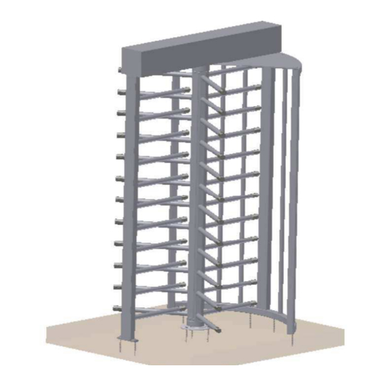
The THT 100 can be configured in a variety of Shield Assembly options. The following shield options are commonly available. B - Shield w/Lexan Pannels A - Standard Shield Figure 3-2: (A) StandardShield and (B) Optional Shield with Lexan Pannels Version : 10//28/2011 Issue : THT-100-IMM-USA REV A6... -
Page 9: Barrier Assembly Options
The Ceiling Plate consists of a flat angled sheet material (in matching finish) which is fixed between the Top Channel Assembly and the Barrier. Ceiling Plate Figure 3-4. Ceiling Plate Exploded View Boon Edam Inc. 402 McKinney Parkway Version: Rev A6 10/28//2011 Tel. 910-814-3800 fax 910-814-3899... -
Page 10: Rotor Arm Options
Figure 3-5. Standard Rotor Arms, (Powder Coat, Stainless or Galvanized) Other possible Options include: A - CSTG C - ASTG B - EL Figure 3-6. Optional Rotor Arms, (CSTG and EL and ASTG) Version : 10//28/2011 Issue : THT-100-IMM-USA REV A6... -
Page 11: Rotor Infill Covers (Option)
3.6 Rotor Infill Covers (Option) Optional infill cover pieces can be ordered which cover the center flange bolt assembly area on the Standard THT-100 rotor arms (note similar snap-in covers are standard on the CSTG, EL and ASTG models). Figure 3-7. Infill Cover (Option) 3.7 Top Chanel Cover Options... - Page 12 Installation and Maintenance Manual Figure 3-9. Two Piece Cover (Option) Figure 3-10. Round Canopy Cover (EL Option) Not pictured top channel cover options. • Hinged Cover • Panel Cover • Square Canopy Version : 10//28/2011 Issue : THT-100-IMM-USA REV A6...
-
Page 13: Control System
THT-100 3.8 Control System The THT-100 Control Box is located in the upper Top Channel Assembly. Typical mains power supplied to the control system is 110-230VAC (refer to project specific drawings and specifications). Within the Control Box, the Main Control Board (MCB) is powered by a 24VAC power supply system which actuates the locking solenoids which in turn allow the turnstile to lock and unlock. -
Page 14: Speed Control Unit
Figure 3-13: Top Channel No Speed Control – Standard Figure 3-14: Top Channel Triangle Speed Control (Option) Figure 3-15: Top Channel Gear Speed Control (Option) Version : 10//28/2011 Issue : THT-100-IMM-USA REV A6... -
Page 15: Operating Concept
4 Operating concept 4.1 Operating functions There are many available operating functions of the THT-100 below is a list of typical configuations. Keep in mind that only one configuration is possible per assembly and is determined when the unit is manufactured. Changing the configuration of the unit can require major mechanical changes. -
Page 16: Access Control System (Acs)
Layout and Rotation Directions 4.2 Access control system (ACS) The THT-100 is designed to integrate with most access control systems by means of an authorization signal. When the THT-100 receives the signal from ACS, the internal control system releases the locking solenoid in the desired rotating direction. -
Page 17: Optional And Configuration Features
The LED’s illuminate Red when the unit is locked and in stand-by waiting for an authorization. When a valid card read signal is sent from the Access Control System to the THT-100, the LED’s on the respective side will turn Green. Once a user passes through the unit, the LED’s will turn back to Red. - Page 18 Figure 4-3. Card Reader Box and Traffic Light (Options) Speed Control Dampening System* THT-100 units are equipped with Optional Speed Control Dampening System to reduce the amount of bounce which the rotor arms can experience after a full rotation when pushed hard.
- Page 19 THT-100 Heel guards* The bottom rotor arms of the THT-100 can be fitted with an optional heel guard protector to reduce direct contact of heels with the rotor arms. If a unit is pushed against a person’s foot or heel the foam rubber protector will reduce the impact.
-
Page 20: Installation
Typical packaging/crating of a THT-100 unit consists of similar packaging pictured below. Note: Tandem and Special order unit crating systems may vary. Verify with Boon Edam for exact crate dimensions and weights. The use of a lift is recommended when receiving and offloading the THT-100 unit. -
Page 21: Tool And Manpower List
THT-100 5.2 Tool and Manpower List Typical THT-100 installations require two men for standing and lifting materials into place. The following tools are needed for installation. • Metric End wrench set • Basic Metric Socket Set • Metric Allen Wrench Set •... -
Page 22: Anchor Locations
Installation and Maintenance Manual 5.5 Anchor Locations The THT-100 unit is secured to the floor at several locations (Note: the Non-secure and Secure side of the turnstile, Counter-Clockwise and Clockwise rotating directions). It is important to layout the unit as illustrated in Figure 5.2 for proper operation. This manual lays out the unit in a Counter Clockwise Rotation. -
Page 23: Floor Layout
5.6 Floor layout Typical Layout* Each THT-100 product will be delivered with a two page set of drawings showing the actual dimensions necessary for layout of the unit. The center point of the unit is the best reference for laying out the unit. Additional floor mounting templates are available upon request. -
Page 24: Mechanical Assembly
Anchor Anchor Secure Hardware Used in this Process Part # Description 3/8” Red Head Anchor HW055 Bolts HW056 3/8” Flat Washer HW057 3/8” Nuts Non-Secure Figure 5-5: Shield and Barrier Anchoring Version : 10//28/2011 Issue : THT-100-IMM-USA REV A6... - Page 25 Description Various Rotor Arm Assembly HW038 M10 x 1.5 x 20 socket head HW003 M10 Spring Lock Washer Figure 5-7: Bottom Rotor Arm Assembly Boon Edam Inc. 402 McKinney Parkway Version: Rev A6 10/28//2011 Tel. 910-814-3800 fax 910-814-3899 Issue: THT-100-IMM-USA...
- Page 26 Infill pieces which do not require the mounting pins (Refer to ASTG/CSTG Installation Appendix for further information. Optional Hardware Used in this Process Part # Description Varies Infill Pieces M6 x 40 socket head Figure 5-9: Optional Rotor Infill Pieces Version : 10//28/2011 Issue : THT-100-IMM-USA REV A6...
- Page 27 ASTG CSTG and EL Rotor Arm Assembly (Option) The rotor arms of the ASTG, CSTG, and EL units assemble in the same manner as the standard THT-100 rotor arms and always include a two piece standard snap-in style infill pieces (see figure 5.11) Figure 5-10.
- Page 28 Alignment of these components will assure the proper resting position of the unit (Reference Figure 5.1 for proper rest position example). Alingment Roll Pin Alignment G Figure 5-12: Top Rotor Arm Assembly Version : 10//28/2011 Issue : THT-100-IMM-USA REV A6...
- Page 29 Hardware Used in this Process Part # Description HW001 M5 x 8 Socket HW016 M5 Spring Lock Washer Figure 5-13: Top Channel and Ceiling Plate Bolt Connections Boon Edam Inc. 402 McKinney Parkway Version: Rev A6 10/28//2011 Tel. 910-814-3800 fax 910-814-3899 Issue: THT-100-IMM-USA...
- Page 30 Hardware Used in this Process Part # Description HW054 M5x0.8 x 13 Bolt HW020 M5 Washer Figure 5-14: Top Channel and Ceiling Plate Connections Version : 10//28/2011 Issue : THT-100-IMM-USA REV A6...
-
Page 31: Electrical Installation
Refer to the electrical drawings (E-drawings) for more detailed information. Mains Electrical Connection Electrical service conduit holes are designed into both mid-posts of the THT-100. There are two holes on each side for running mains power, access control, fire alarm or other necessary communications to the unit. -
Page 32: Main Control Box
Installation and Maintenance Manual 5.9 Main Control Box Cable Connections There are many cables which connect to the Main Control Box. The following cable plugs are typical on the THT-100: Factory Connected : • KS 1 and 2 – Key Switch •... - Page 33 Units using dual phase 220 VAC, requires an additional factory supplied fuse located inside the control box. Reference electrical drawings in the appendix 11.2 for additional information. Boon Edam Inc. 402 McKinney Parkway Version: Rev A6 10/28//2011 Tel. 910-814-3800 fax 910-814-3899...
- Page 34 SOL ACT SW1 – Solenoid Activation Switch 1 • SOL ACT SW2 – Solenoiod Activation Switch 2 • ROT DET SW 1 – Rotation Detection Switch ACW • ROT DET SW 2 - Rotation Detection Switch CW Version : 10//28/2011 Issue : THT-100-IMM-USA REV A6...
-
Page 35: Configuration
Serial Port Interface – Allows the MCB to react to wet voltages (3-25vdc) in leu of dry contact inputs on the X1 terminals. Options for signal transmission TD or SD (Transmit Data), DTR (Data Terminal Ready), RTS (Request to Send Data). Start-up Boon Edam Inc. 402 McKinney Parkway Version: Rev A6 10/28//2011 Tel. 910-814-3800 fax 910-814-3899... -
Page 36: General
Persons should remain clear of the THT-100 top channel mechanism’s moving parts. 5.11 General The THT-100 will be pre-configured by Boon Edam and is ready for general use after proper installation. Setting up the THT-100 for operation can be accomplished by using the start procedure as described below. -
Page 37: Parts Overview
THT-100 6 Parts Overview 6.1 THT100- Exploded View Figure 6-1: THT-100 Exploded View Part Description Side Shield Card Reader Bracket (Optional) Top Channel Cover Top Channel Mechanism Ceiling Plate Top Flange Assembly Bottom Flange Assembly Base Plate Assembly (w/Bearing) Rotor Arm Assembly (3 Each) -
Page 38: Safety Inspections And Maintenance
8.2 Semi-Annual Planned Maintenance It is recommended that a minimum of two planned maintenance inspections be performed on the equipment by an Authorized Boon Edam agent to assure proper operation and optimal function. General Inspection •... - Page 39 Inspect Fire Alarm functions (if connected) • Inspect Power failure functions • Inspect Dampening system (if equipped) to ensure rotor arms rotate and rest smoothly. Boon Edam Inc. 402 McKinney Parkway Version: Rev A6 10/28//2011 Tel. 910-814-3800 fax 910-814-3899 Issue: THT-100-IMM-USA...
-
Page 40: Maintenance Checklist
......Function: ..... . (Signature and Date) Table 8.1: Maintenance checklist Version : 10//28/2011 Issue : THT-100-IMM-USA REV A6... -
Page 41: Troubleshooting
The fuses are located in the power connection box on the MCB. • Powering down the entire THT-100 by shutting down the power and waiting for approx. 30 seconds before powering it back up. •... -
Page 42: Technical Specifications
Approx: 800lbs (360kg), including crate (standard version) Installation: Typical Concrete type anchors Cabling: Power supply, fire alarm & communication cables (see drawings) Power supply: Configurable 110-240 VAC, 50/60 Hz Mains Fuse: 2.5 Amp Version : 10//28/2011 Issue : THT-100-IMM-USA REV A6... -
Page 43: Appendices
Typical for FS/FL Combo 100-131 Connecting Spring Typical for FS locking 101-012 2 Way Microswitch Home Position/Rotation Det. 101-015 Microswitch Gasket Isolation material for microswitch Boon Edam Inc. 402 McKinney Parkway Version: Rev A6 10/28//2011 Tel. 910-814-3800 fax 910-814-3899 Issue: THT-100-IMM-USA... -
Page 44: Electrical Schematics
Installation and Maintenance Manual 11.2 Electrical Schematics Table 11.1: Electrical Schematic Version : 10//28/2011 Issue : THT-100-IMM-USA REV A6... -
Page 45: Tht100- Tandem Unit
THT-100 11.3 THT100- Tandem Unit The THT-100 is available in a Tandem Unit which incorporates two sets of rotor arms and mechanisms into one extended top channel unit as illustrated in figure below. Installation follows the typical THT100 unit. Part Description... -
Page 46: Tastg - Curved Shield Tandem Unit
Installation and Maintenance Manual 11.4 TASTG – Curved Shield Tandem Unit Figure 11-1, TASTG 11.5 THT-100TL – Tandem Unit. Figure 11-2, TL Tandem Version : 10//28/2011 Issue : THT-100-IMM-USA REV A6... -
Page 47: Enclosures
THT-100 Enclosures In this chapter specific information regarding the project can be added. Boon Edam Inc. 402 McKinney Parkway Version: Rev A6 10/28//2011 Tel. 910-814-3800 fax 910-814-3899 Issue: THT-100-IMM-USA... - Page 48 Installation and Maintenance Manual Royal Boon Edam International B.V. Boon Edam Ireland Ltd. Boon Edam Spain S.L. Ambachtstraat 4 / 1135 GG EDAM Unit 1 Naas Road Business Park, C/Palència, 14-16 1° 4a P.O. Box 40 / 1135 ZG EDAM...
Need help?
Do you have a question about the THT-100 and is the answer not in the manual?
Questions and answers