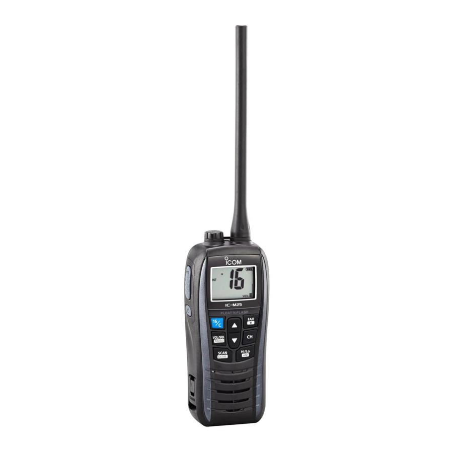
Icom IC-M25 Instruction Manual
Vhf marine transceiver
Hide thumbs
Also See for IC-M25:
- Instruction manual (48 pages) ,
- Service manual (27 pages) ,
- Instruction manual (48 pages)

Related Manuals for Icom IC-M25


Summary of Contents for Icom IC-M25
- Page 1 INSTRUCTION MANUAL VHF MARINE TRANSCEIVER iM25 iM25EURO This device complies with Part 15 of the FCC Rules. Operation is subject to the condition that this device does not cause harmful interference.
-
Page 2: Foreword
FOREWORD FEATURES Thank you for purchasing this Icom radio. The IC-M25/IC- Floats on water VHF MARINE TRANSCEIVER M25EURO is designed and built The transceiver floats in fresh or salt with Icom’s state of the art technology and craftsmanship. water even when the supplied acces- With proper care this radio should provide you with years of sories are attached. -
Page 3: In Case Of Emergency
IN CASE OF EMERGENCY RECOMMENDATION If your vessel requires assistance, contact other vessels and CLEAN THE TRANSCEIVER THOROUGHLY WITH FRESH the Coast Guard by sending a distress call on Channel 16. WATER after exposure to saltwater, and dry it before operat- ing. - Page 4 ALWAYS keep the antenna at least 2.5 cm (1 inch) away from the body Electromagnetic Fields. when transmitting and only use the Icom belt clip which is listed on page 43 when attaching the radio to your belt, etc., to ensure FCC and IC RF exposure compliance requirements are not exceeded.
- Page 5 RF supérieures aux limites établies par la FCC Interférence électromagnétique et compatibilité En mode de transmission, votre radio Icom produit de l'énergie de RF qui peut provoquer des interférences avec d'autres appareils ou systèmes. Pour CAUTION éviter de telles interférences, mettez la radio hors tension dans les secteurs...
-
Page 6: Precautions
KEEP from your vessel’s magnetic navigation compass. Icom, Icom Inc. and Icom logo are registered trademarks of Icom Incorporated (Japan) in Japan, the United States, the United Kingdom, Germany, France, Spain, Russia, Australia, New Zealand, and/or other countries. -
Page 7: Table Of Contents
FOREWORD ..................i Lock function ................13 IMPORTANT ..................i Monitor function ..............13 EXPLICIT DEFINITIONS ..............i Automatic backlighting ............13 FEATURES ..................i AquaQuake Water Draining function........13 IN CASE OF EMERGENCY ............. ii RECOMMENDATION ............... ii 5 SCAN OPERATION ............14–15 SAFETY TRAINING INFORMATION ..........iii Scan types ................14 INFORMATION EN MATIÈRE DE SÉCURITÉ... -
Page 8: Fcc Information
CAUTION: Changes or modifications to this device, not ex- pressly approved by Icom Inc., could void your authority to operate this device under FCC regulations. -
Page 9: Operating Rules
It is unlawful to operate a ship station which is not licensed, but required to be. NOTE: Even though the IC-M25/IC-M25EURO is capable of operation on VHF marine channels 3, 21, 23, 61, 64, If required, contact your dealer or the appropriate govern- ment agency for a Ship-Radiotelephone license application. -
Page 10: Supplied Accessories And Attachments
SUPPLIED ACCESSORIES ATTACHMENTS Supplied accessories D Handstrap Handstrap Charger* Belt clip Pass the handstrap through the loop on the back side of the transceiver as shown. Antenna D Belt clip * Not supplied, depending on the version) Attach the belt clip to, or detach the belt clip from the transceiver. To attach the belt clip To detach the belt clip Lift the tab up (q), and slide... - Page 11 SUPPLIED ACCESSORIES AND ATTACHMENTS Charger D Charging from other than supplied charger IMPORTANT: Prior to use the transceiver for the first time, fully charge the battery for optimum life and opera- tion. To avoid damage to the battery, turn OFF the power *Some PCs may not supply while charging.
-
Page 12: Panel Description
PANEL DESCRIPTION Nomenclature and main functions ANTENNA CONNECTOR (p. 2) Antenna connector Connect the supplied antenna. [SP/MIC] JACK SPEAKER/MIC JACK [SP/MIC] (p. 23) Connect the optional speaker microphone (HM-213) here. 1) Rotate the cap counter clockwise. 2) Pull the cap up to detach it. Function display [UP/DWN] [FAV]... -
Page 13: Panel Description
PANEL DESCRIPTION VOLUME/SQUELCH/MONITOR KEY [VOL/SQL MONI] UP/DOWN KEYS [Y] or [Z] Push when you adjust the volume level. While the "VOL" icon blinking, push [UP]/[DWN] to adjust the vol- FAVORITE/TAG KEY [FAV TAG] ume level. Push to sequentially select the favorite (TAG) channels The Volume Mute function: Hold down for 1 second to set or clear the selected While holding down this key, push [Z] to temporary... -
Page 14: Function Display
PANEL DESCRIPTION Function display CHANNEL NUMBER READOUT BUSY ICON ATIS TRANSMIT ICON BATTERY ICONS TAG CHANNEL ICON LOW POWER INDICATOR DUPLEX INDICATOR SCAN INDICATOR CHANNEL GROUP INDICATOR DUALWATCH INDICATOR TRI-WATCH INDICATOR VOLUME/SQUELCH LEVEL ICON KEY LOCK ICON WX channel is selected WX Alert Blinks while adjusting. - Page 15 PANEL DESCRIPTION SCAN INDICATOR (p. 15) WEATHER CHANNEL/WEATHER ALERT ICONS “WX” appears when the weather channel group is se- lected. LOCK ICON (p. 13) “ ” appears while the Weather Alert function is turned Appears when the Lock function is turned ON. ON, and blinks when the alert tone is received.
-
Page 16: Basic Operation
BASIC OPERATION Selecting channel D Selecting regular channel Choose the appropriate channel groups for your operating area, and then select the channel. Push [Y] or [Z] to select a channel. DUP” appears for duplex channels. D Selecting channel group tional and 65 Canadian channels. Hold down [U/I/C] (CH/WX) for 1 second to change the channel group. -
Page 17: Weather Channels
D Channel 16 D Weather channels Channel 16 is the distress and safety channel. It is used for The transceiver has 10 weather channels. These are used establishing initial contact with a station, and for emergency for monitoring broadcasts from NOAA (National Oceanic and communications. -
Page 18: Adjusting The Volume Level
Receiving and transmitting IMPORTANT: To maximize the readability of your trans- CAUTION: Transmitting without an antenna can damage mitted signal, pause for a second after pushing [PTT], the transceiver. hold the microphone 5 to 10 cm (2 to 4 inches) from your mouth and speak into the microphone at a normal voice q Push [Y] or [Z] to select the channel. - Page 19 Adjusting the squelch level Monitor function Squelch is a function that allows the audio to be heard only The Monitor function momentary cancels the squelch func- while receiving a signal that is stronger than a set level. You tion. You can check for weak signals including noise. can adjust the squelch threshold level.
-
Page 20: Volume Loud Function
Volume Loud function Lock function This function electronically locks the keys to prevent acci- You can temporary maximize the volume level with a simple dental changing of the channel and function access. operation. Hold down [ ] (Hi/Lo) for 1 second to turn the function q While holding down [VOL/SQL], push [Y]. - Page 21 Setting TAG channels Setting the Call channel You can quickly recall often-used channels by tagging them You can recall the most often-used channel with a single op- as TAG channels. eration, by setting the channel as a Call channel. TAG channels can be independently assigned to each chan- A Call channel can be set in each channel group.
-
Page 22: Scan Operation
SCAN OPERATION Scan types You can efficiently locate signals over the channels by scan- ning. You can find the ongoing call by scanning the TAG channel. Before starting to scan: PRIORITY SCAN nels to be scanned, before scanning. A priority scan sequentially searches through all TAG in the Set mode. - Page 23 SCAN OPERATION Start to scan q Hold down [U/I/C] (CH/WX) for 1 second one or more times to select a desired channel group. weather channel using [CH/WX] and [Y] or [Z]. w Push [SCAN] to start a scan. SCAN” blinks while scanning. disappears, or resumes after pausing 5 seconds, depending on the Set mode setting.
-
Page 24: Dualwatch/Tri-Watch
DUALWATCH AND TRI-WATCH Description Operation Dualwatch/Tri-watch are convenient for monitoring Channel w Select the desired channel. 16 when you are operating on another channel. e Hold down [DUAL] (SCAN) for 1 second to start Dual- Dualwatch monitors Channel 16 while you are receiving on another channel. -
Page 25: Set Mode
SET MODE Set mode programming D Set mode operation The Set mode is used to select an option for the transceiv- q Turn OFF the power. er's functions. w While holding down [VOL/SQL], turn ON the power to enter the Set mode. e While holding down [VOL/SQL], push [Y] or [Z] to select an item. -
Page 26: Set Mode Items
SET MODE Set mode items D Priority Scan function D Beep Tone function “Prio” “bEEP” The transceiver has 2 scan types— Normal (OFF) and Pri- Turn the key touch beep sound ON or OFF. ority (ON) scan. A normal scan searches all TAG channels in the selected channel group. - Page 27 SET MODE D Auto Scan function D Monitor key action “Auto” “SqLS” The Auto Scan function automatically starts a normal or The monitor key momentary cancels the squelch function. priority scan when no signal is received, and no operation is Select a key action option.
- Page 28 SET MODE D Automatic backlighting D Power Save function “A_bL” “P_SA” This function is convenient for the operation in the night. The The Power Save function reduces current drain by periodi- backlight can be selected from ON and OFF. cally turning OFF the receiver circuit. [PTT] is pushed.
-
Page 29: Battery Caution
When the battery life cycle is shorter, it is time to replace it with a new one. Contact your Icom's local service shop about replacing the inside battery pack. - Page 30 Turn OFF the power. Then, insert the speaker-mic connector and allows you to talk and listen more easier. The HM-213 into the [SP MIC] connector and carefully screw it tight, as speaker microphone is prepared for the IC-M25/M25EURO. CAUTION: Attach the speaker-microphone’s Alligator type clip connector securely to prevent accidental To attach the speaker-mic.
-
Page 31: Troubleshooting
TROUBLESHOOTING PROBLEM POSSIBLE CAUSE SOLUTION The transceiver does not turn ON. No sound from speaker. squelch level to the threshold level. Transmitting is impossible, or high power can not be se- or only receive. lected. [Hi/Lo] to select high power. The displayed channel cannot ] (Hi/Lo) for 1 second to be changed. -
Page 32: Vhf Marine Channel List
VHF MARINE CHANNEL LIST hannels (for U.K. version only) Frequency (MHz) Frequency (MHz) Frequency (MHz) Frequency (MHz) Frequency (MHz) Frequency (MHz) Transmit Receive Transmit Receive Transmit Receive Transmit Receive Transmit Receive Transmit Receive 156.050 156.050 156.600 156.600 157.100 157.100 156.225 156.225 156.775 156.775... - Page 33 VHF MARINE CHANNEL LIST Frequency (MHz) Frequency (MHz) Frequency (MHz) Frequency (MHz) Frequency (MHz) Frequency (MHz) Transmit Receive Transmit Receive Transmit Receive Transmit Receive Transmit Receive Transmit Receive 156.050 160.650 156.550 156.550 157.050 161.650 156.075 160.675 156.575 156.575 157.075 161.675 156.100 160.700 156.600...
-
Page 34: Specifications And Options
D TRANSMITTER used with an Icom transceiver. Icom is not responsible for the destruction or damage to an Icom transceiver in the event the Icom transceiver is used with equipment that is not manufactured or approved by Icom. Some options may not be available in some countries. Please ask your dealer for details. - Page 35 MEMO...
- Page 36 MEMO...
- Page 37 MEMO...
- Page 38 A-7227-1EX Printed in Japan 2015 Icom Inc. © 1-1-32 Kamiminami, Hirano-ku, Osaka 547-0003, Japan Printed on recycled paper with soy ink.
Need help?
Do you have a question about the IC-M25 and is the answer not in the manual?
Questions and answers