Table of Contents
Advertisement
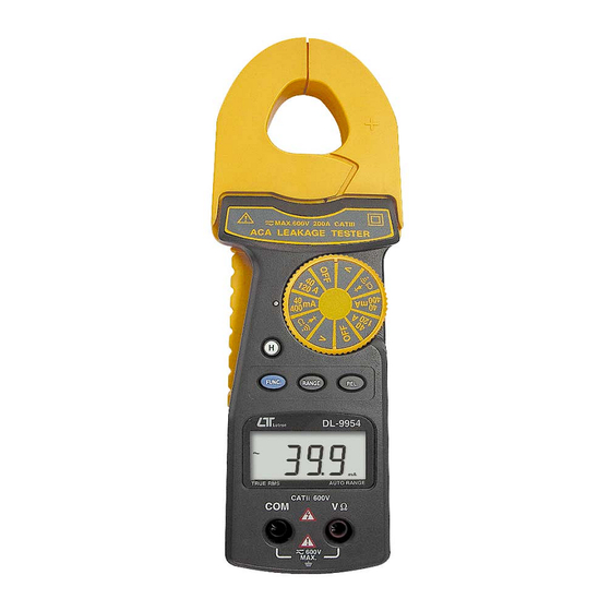
auto range, true rms
ACA LEAKAGE
TESTER
Model : DL-9954
OPERATION MANUAL
Your purchase of this ACA
LEAKAGE TESTER marks a
step forward for you into
the
field
of
measurement.
this ACA LEAKAGE TESTER
is a complex and delicate
instrument,
structure will allow many
years of use if proper
operating techniques are
developed.
Please
the following instructions
carefully and always keep
this manual within easy
reach.
precision
Although
its
durable
read
Advertisement
Table of Contents

Related Manuals for Lutron Electronics DL-9954


Summary of Contents for Lutron Electronics DL-9954
- Page 1 ACA LEAKAGE TESTER Model : DL-9954 Your purchase of this ACA LEAKAGE TESTER marks a step forward for you into field precision measurement. Although this ACA LEAKAGE TESTER is a complex and delicate instrument, durable structure will allow many...
- Page 2 Caution Symbol Caution : * Risk of electric shock ! Caution : * Do not apply the overload voltage, current to the input terminal ! * Remove test leads before open the battery cover ! * Cleaning - Only use the dry cloth to clean the plastic case ! * Double insulation * Function earth...
-
Page 3: Table Of Contents
TABLE OF CONTENTS 1 FEATURES..............1 2 SPECIFICATIONS............1 2-1 General Specifications..........1 2-2 Electrical Specifications.......... 3 3 FRONT PANEL DESCRIPTION........5 4 PRECAUTIONS & PREPARATIONS FOR MEASUREMENT............6 5 MEASURING PROCEDURE..........7 5-1 Symbols & Units of Display ........7 5-2 DCV, ACV Measurement ........8 5-3 Resistance Measurement........8 5-4 Continuity Check ..........8 5-5 Diode Test............ -
Page 4: Features
1. FEATURES * High precision AC mA measurement, it is useful for AC mA leakage current measurement. * Measure AC mA on the inductive conductor. * Design meet IEC 1010 CATIII 600V safety requirement. * 4000 counts, auto range and multi-functions. * Measurement for ACA, ACV, DCV, Ohms, Diode, Continuity beeper. - Page 5 Polarity Automatic Switching, " - " indicates negative polarity. Over-input Indication of " OL ". Sampling Time Approx. 0.35 second. Battery 2 x 1.5 V AA ( UM-3 ) batteries. Operating 0 to 50 ( 32 to 122 ℃ ℉ Temperature Operating Less than 80% RH.
-
Page 6: Electrical Specifications
2-2 Electrical Specifications (23± 5 ℃ Function Range Reso- Accuracy Overload lution Protection 400 mV 0.1 mV ± ( 0.5 % + 2d ) DC only DCV : 0.001V 40 V 0.01V ± ( 1 % + 2d ) ( true rms ) 400 V ACV : 0.1 V... - Page 7 Function Range Reso- Accuracy Overload lution Protection Ohms 400 ohm 0.1 ohm 4 K ohm 1 ohm 40 K ohm ± ( 1 % + 5d ) 10 ohm 400 K ohm 100 ohm 4 M ohm ± ( 2 % + 2d ) 1 K ohm AC / DC 400 V 40 M ohm...
-
Page 8: Front Panel Description
3. FRONT PANEL DESCRIPTION Fig. 1 3-1 Current Sense Jaws 3-2 Trigger 3-3 Function Indicator 3-4 Function rotary switch 3-5 Range button 3-6 Hold button 3-7 FUNC. button ( Function button ) 3-8 REL. button ( Relative button ) 3-9 Display 3-10 Input terminal 3-11 Battery compartment/Cover... -
Page 9: Precautions & Preparations For Measurement
4. PRECAUTIONS & PREPARATIONS FOR MEASUREMENT 1)Ensure that the DC 1.5V x 2 batteries are connected with the right polarity and placed in the battery compartment correctly. 2)Place the Red & Black Test Leads into the proper input terminal before making measurement. 3)Remove either of the test leads from the circuit when changing the measurement function. -
Page 10: Measuring Procedure
5. MEASURING PROCEDURE 5-1 Symbols & units of display Symbols / Descriptions Units Appears when selecting DCV mode. Appears when selecting ACV & ACA mode. Appears when the " Data hold " function is operated. Appears when the " Relative " function is operated. -
Page 11: Dcv, Acv Measurement
5-2 DCV, ACV Measurement 1)Connect BLACK test lead into " COM " terminal. 2)Connect RED test lead into " V Ω " terminal. 3)If measure " DCV ", select the " Function rotary switch " ( 3-4, Fig. 1 ) to the " V " position then push the "... -
Page 12: Diode Test
the " " position then push the " FUNC. button " ( 3-7, Fig. 1 ) for display show " ". 4)when the resistance value is less than 10 ohm, the beeper sound will be generated. 5-5 Diode Test 1)Connect BLACK test lead into " COM " terminal. 2)Connect RED test lead into "... -
Page 13: Ac Leakage Current, Ac Current Measurement
5-6 AC leakage Current, AC Current Measurement 1)AC leakage Current Select the " Function rotary switch " ( 3-4, Fig. 1 ) to the " 40 mA/400 mA " position. AC Current Measurement Select the " Function rotary switch " ( 3-4, Fig. 1 ) to the "... -
Page 14: Relative Measurement
5-7 Relative Measurement 1)During the measurement of ACV, ACA, DCV and ohm, the circuit will memorize the last measured values if push the " REL. button " ( 3-8, Fig. 1 ) at once, then LCD will show zero value & a " REL. " indicator. 2)The input measured values will deduct last measured values "... -
Page 15: Maintenance
6. MAINTENANCE 6-1 Battery replacement Caution : Remove test leads before opening the battery cover ! 1)When the LCD display showing the mark of " ", it is necessary to replace the battery, However in-spec. measurement may still be made for several hours after "... -
Page 16: Optional Accessories & Adapter
7. OPTIONAL ACCESSORIES & ADAPTER Item Model Carrying Case CA-52A Light Adapter LX-02 EMF Adapter EMF-824 Pressure Adapter PS-403 Anemometer Adapter AM-402 Tachometer Adapter TA-601 Sound Adapter SL-406 High Voltage Probe HV-40... -
Page 17: The Address Of After Service Center
8. THE ADDRESS OF AFTER SERVICE CENTER 1103-DL9954A...
Need help?
Do you have a question about the DL-9954 and is the answer not in the manual?
Questions and answers