Table of Contents
Advertisement
Quick Links
DIGITAL
STROBOSCOPE
Model : DT-2239A
Your purchase of this DIGITAL STROBOSCOPE marks a step
forward for you into the field of precision measurement.
Although this STROBOSCOPE is a complex and delicate
instrument, its durable structure developed. Please read the
following instructions carefully and always keep this manual
within easy reach.
OPERATION MANUAL
Advertisement
Table of Contents

Related Manuals for Lutron Electronics DT-2239A


Summary of Contents for Lutron Electronics DT-2239A
- Page 1 DIGITAL STROBOSCOPE Model : DT-2239A Your purchase of this DIGITAL STROBOSCOPE marks a step forward for you into the field of precision measurement. Although this STROBOSCOPE is a complex and delicate instrument, its durable structure developed. Please read the following instructions carefully and always keep this manual within easy reach.
- Page 2 Warning Do not look directly at strobe/reflector. Light pulses at the frequency greater than 5 Hz may cause photosensitive epilepsy in some individuals if directly viewed. A feature of the instrument is to make moving objects appear to be stationary. Precaution should therefore be taken to ensure that there is no physical contact made with objects being viewed.
- Page 3 Caution Symbol Caution : * Risk of electric shock ! Caution : Do not use fingers or any tool to touch the FLASH TUBE. The instrument contains no user serviceable parts and should not be opened by the user. Repair or after service should be done by a qualified technician only.
-
Page 4: Table Of Contents
TABLE OF CONTENTS 1. FEATURES..............2. SPECIFICATIONS............2-1 General Specification........... 2-2 Flash Tube Specification........3. FRONT PANEL DESCRIPTION........3-1 Power On/Off Switch........... 3-2 Low/High Range Select Switch......3-3 Fine Adjust Knob..........3-4 Coarse Adjust Knob..........3-5 Flash Tube............3-6 Auto Range Indicator.......... 3-7 Display............... -
Page 5: Features
1. FEATURES The Digital Stroboscope is a microprocessor circuit design, high accuracy, digital readout, light duty, that is ideal for inspecting and measuring the speed of moving gears, fans, centrifuges, pumps, motors and other equipment used in general industrial maintenance, production, quality control, laboratories and as well as for schools and colleges for demonstrating strobe action. -
Page 6: Flash Tube Specification
Power Supply 110 Vac 10%, 50/60 Hz. 220 Vac 10%, 50/60 Hz. 230 Vac 10%, 50/60 Hz. 240 Vac 10%, 50/60 Hz. Power Less than 30 Watt. Consumption Operating Temp. 0 to 50 ( 32 to 122 ℃ ℉ Operating Less than 80% R.H. -
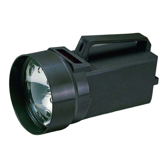
Page 7: Front Panel Description
3. FRONT PANEL DESCRIPTION Fig. 1 Symbol : 3-1 Power On/Off Switch 1 = On 3-2 Low/High Range Select Switch 0 = Off 3-3 Fine Adjust Knob 3-4 Coarse Adjust Knob 3-5 Flash Tube 3-6 Auto Range Indicator 3-7 Display 3-8 Power Cord Input Socket 3-9 Power Cord Connector 3-10 Power Cord Plug... -
Page 8: Measuring Procedures
4. MEASURING PROCEDURE Caution : * Do not use fingers or any tool to touch the FLASH TUBE. * Risk of electric shock ! 4-1 Preparation a. Connect the " Power Cord Connector " (3-9, Fig. 1) to the " Power Cord Input Socket " (3-8). Plug the " Power Cord Plug "... -
Page 9: Checking Motion
a. Power off the installation to be measured, make a " mark " on the rotation area where it is intended to measure the RPM. Then power on the installation to be measured. b. When checking the speed, care must be taken to ensure that the strobe is flashing in unison (one to one) with the object being monitored. -
Page 10: The Address Of After Service Center
6. THE ADDRESS OF AFTER SERVICE CENTER 0804-DT2239...
Need help?
Do you have a question about the DT-2239A and is the answer not in the manual?
Questions and answers