Table of Contents
Advertisement
Quick Links
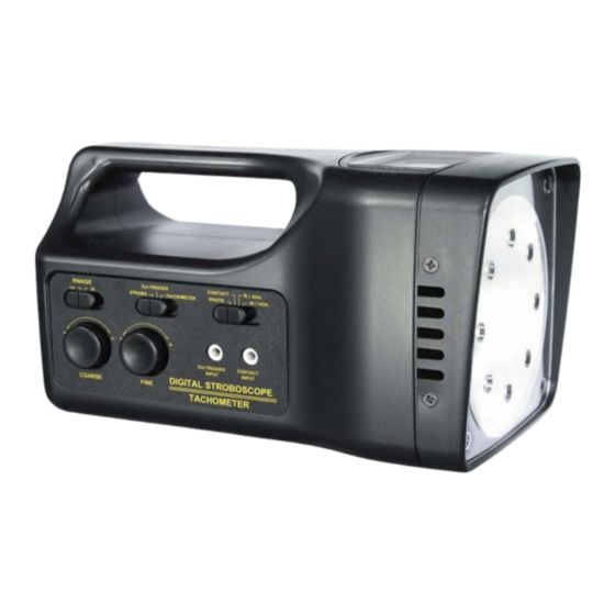
XENON, AC power or Battery power
STROBOSCOPE
Model : DT-2289
Your purchase of this STROBOSCOPE marks a step forward for
you into the field of precision measurement. Although this
METER is a complex and delicate instrument, its durable structure
developed. Please read the following instructions carefully and
always keep this manual within easy reach.
OPERATION MANUAL
Advertisement
Table of Contents

Subscribe to Our Youtube Channel
Related Manuals for Lutron Electronics DT-2289


Summary of Contents for Lutron Electronics DT-2289
- Page 1 XENON, AC power or Battery power STROBOSCOPE Model : DT-2289 Your purchase of this STROBOSCOPE marks a step forward for you into the field of precision measurement. Although this METER is a complex and delicate instrument, its durable structure developed. Please read the following instructions carefully and always keep this manual within easy reach.
- Page 2 Warning Do not look directly at strobe/reflector. Light pulses at the frequency greater than 5 Hz may cause photosensitvie epilepsy in some individuals if directly viewed. A feature of the instrument is to make moving objects appear to be stationary. Precaution should therefore be taken to ensure that there is no physical contact made with objects being viewed.
-
Page 3: Caution Symbol
Caution Symbol Caution : * Risk of electric shock ! Caution : * Do not use fingers or any tool to touch the FLASH TUBE. * The instrument contains no user serviceable parts and should not be opened by the user. * Repair or after service should be done by a qualified technician only. - Page 4 TABLE OF CONTENTS 1 FEATURES..............1 2 SPECIFICATIONS............2 3 FRONT PANEL DESCRIPTION........6 3-1 Power On/Off Switch..........8 3-2 DC9V Power Adapter Input Socket......8 3-3 High, Low Range Switch........8 3-4 Stroboscope, Ext. Trigger, Tachometer Switch..8 3-5 Photo Tach, Contact Tach, ft/min.. m/min SW..8 3-6 Coarse Adjust Knob..........8 3-7 Fine Adjust Knob..........8 3-8 Ext.
- Page 5 1. FEATURES * Combination Stroboscope with 3 functions : Digital Stroboscope, Laser Photo Tachometer, Contact Tachometer ( optional probe ), 3 in 1 , intelligent function. * The Digital Stroboscope is used the microprocessor circuit design, high accuracy, digital readout, light duty, that is ideal for inspecting and measuring the speed of moving gears, fans, centrifuges, pumps, motors and other equipment used in general industrial...
-
Page 6: Specifications
2. SPECIFICATIONS 2-1 General Specifications Display 5 digits ( 0 to 99999 ) LCD display. Circuit Exclusive one-chip design microprocessor LSI circuit. Stroboscope Measurement Unit : FPM ( rotation per minute ). build in external trigger input. Laser Photo Tachometer Unit : RPM ( rotation per minute ). - Page 7 Accessories Operation manual......1 PC. Included AC( 100V to 240V ) to DC 9V adapter .............1 PC. Reflective tape....... 1 PC. Optional Contact Tachometer probe Accessory ........ Model : TA-35 Flash Xenon tube..Model : TBXE-2289 2-2 Electrical Specifications of Stroboscope Stroboscope Specification Stroboscopic 100 to 15,000 flashes per minute (FPM).
- Page 8 Flash tube It is required to change the flash tube replacement when the instrument start to flash irregularly at speeds of 3600 RPM/FPM or more. Flash tube with plug and socket, easy to make the replacement. Operating duty For prolong life and safety, please Cycle adhere to the following operation duty cycle: <...
- Page 9 Resolution 0.1 RPM < 1,000 RPM 1 RPM 1,000 RPM ≧ Time base Quartz crystal Laser light * Less than 1 mW. source * Class 2 laser diode. Red. Wave length is 645 nm approximately. 2-4 Electrical Specifications of Contact Tachometer ( Optional Probe, TA-35 ) Contact Tachometer : Range...
-
Page 10: Front Panel & Layout Description
4. FRONT PANEL & LAYOUT DESCRIPTION Fig. 1... - Page 11 Fig. 1...
- Page 12 Fig. 1 3-1 Power On/Off Switch 3-2 DC 9V Power Adapter Input Socket 3-3 High, Low Range Switch 3-4 Stroboscope, Ext. Trigger, Tachometer Switch 3-5 Photo Tach, Contact Tach, ft/min.. m/min Switch 3-6 Coarse Adjust Knob 3-7 Fine Adjust Knob 3-8 Ext.
-
Page 13: Power Supply Consideration
4. POWER SUPPLY CONSIDERATION 1) The instrument is shipped along with an ACV ( 100V to 240V ) to DC 9V ( 3A ) adapter. 2) When operate the instrument, it should insert the DCV output plug of DC adapter into the " DC 9V Power Adapter Input Socket "... -
Page 14: Stroboscope Measuring Procedures
5. STROBOSCOPE MEASURING PROCEDURES Caution : * Do not use fingers or any tool to touch the FLASH TUBE. * Risk of electric shock ! 5-1 Preparation 1) Connect the DCV output plug of DC adapter into the " DC 9V Power Adapter Input Socket " ( 3-2, Fig. 1 ) Connect the ACV input plug of DC adapter into the a properly 110V AC, 220V AC or 240V AC outlet. - Page 15 5-2 Checking Speed (RPM/FPM) Caution : * Operating duty cycle should be followed. For prolong life and safety, please adhere to the following operation duty : Below 2,000 RPM - 30 Minutes. Above 2,000 RPM - 5 Minutes. * Always allow a 10 minute cooling off period between cycles. 1) Power off the installation to be measured, make a "...
- Page 16 5-3 Checking Motion For motion analysis, simply locate the actual speed as mentioned above and then turn the dial slowly up or down. This will give a slow motion effect allowing complete inspection. 5-4 External trigger The stroboscope can accept the external trigger signal instead of the internal trigger ( setting the value by knobs ).
- Page 17 6. LASER PHOTO TACHOMETER MEASURING PROCEDURES 1) Select the " Stroboscope, Ext. Trigger, Tachometer Switch " ( 3-4, Fig. 1 ) to the " Tachometer " position. 2) Select The " Photo Tach, Contact Tach, ft/min.. m/min Switch " ( 3-5, Fig. 1 ) to the " Photo Tach " position. 3) Adhesive a reflecting mark to the object being measured.
- Page 18 7. CONTACT TACHOMETER MEASURING PROCEDURES 1) Prepare a optional Contact Tachometer Probe " Model : TA-35 ". The standard accessories of TA-35 are included : RPM adapter ( Cone type )....RPM adapter ( Funnel type )....Surface speed test wheel....... 2) Insert the output plug of the "...
- Page 19 RPM measurement 4) Select The " Photo Tach, Contact Tach, ft/min., m/min Switch " ( 3-5, Fig. 1 ) to the " Contact Tach " position. 5) Pressing the " RPM Adapter " lightly against the center hole on the hole of the measured rotating axis. Note : Making the contact RPM measurement due to different kind measured rotating axis, it may...
-
Page 20: Flash Tube Replacement
8. FLASH TUBE REPLACEMENT The flash tube requires changing when the instrument start to flash erratically at speeds of 3600 RPM/FPM or more. Caution : * Change of the Flash Tube should only be done by a qualified technician. As the instrument contains no user serviceable parts. -
Page 21: The Address Of After Service Center
9. THE ADDRESS OF AFTER SERVICE CENTER 0411-DT2289...
Need help?
Do you have a question about the DT-2289 and is the answer not in the manual?
Questions and answers