
Subscribe to Our Youtube Channel
Related Manuals for lavina 20n-x

Summary of Contents for lavina 20n-x
- Page 1 LAVINA 20N-X User Manual ® Tech Support Line: 800-987-8403 | www.superabrasive.com | info@superabrasive.us ...
- Page 2 Superabrasive User Manual Original Language Lavina® 20N‐X 6/2017 2 ...
-
Page 3: Warranty And Returns
The warranty herein is non-transferable, and only applies to the original owner or purchaser of the machine. RETURN POLICY FOR LAVINA® X MACHINES The LAVINA® X machines may be returned, subject to the following terms: In no case, a machine is to be returned to Superabrasive Inc. for credit or repair without prior authorization. -
Page 4: Table Of Contents
Vacuum Connection .............. 6 MECHANICAL PARTS .............. 15 TECHNICAL DATA ................ 6 Electrical System ............... 16 VIBRATIONS ................ 6 SINGLE phase or three phase connection ......... 16 2. SAFETY INSTRUCTIONS ............ 6 Lavina® 20N‐X Electrical ............ 17 Recommended Use .............. 6 schemes with Yaskawa Inverter 200‐240 Volt ...... 17 Prohibited Use ................ 6 8.TROUBLESHOOTING ............... 18 Preparation for work .............. 6 Index of Problems and Solutions .......... 18 Protection Devices .............. 7 8.1 Replacing Power Cord and Plugs ... -
Page 5: General Information
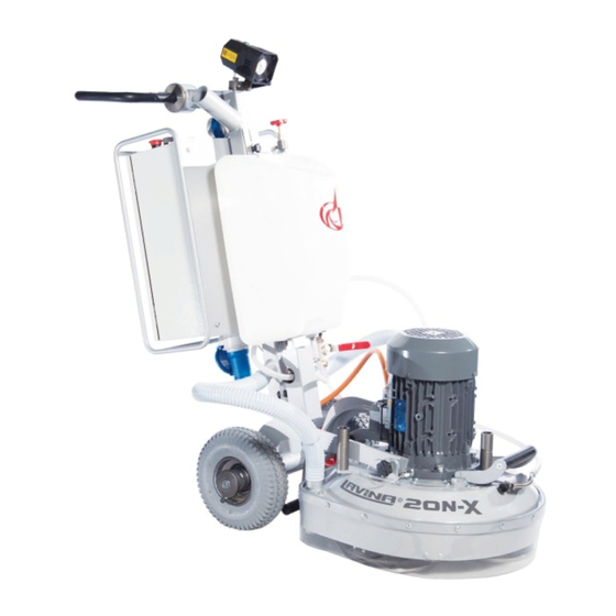
Superabrasive User Manual Original Language Lavina® 20N‐X 6/2017 1. GENERAL INFORMATION This owner’s manual is intended for the operator of the LAVINA® X machine, the servicing technician as well as anyone else involved with operating or servicing the machine. We recommend that you read the instructions carefully and follow them strictly. The manual includes information about assembling, using, handling, adjusting and maintaining your LAVINA® X floor grinding and polishing machine. MANUFACTURER Superabrasive was founded in 1987, as a manufacturer of high quality diamond tools for the stone and concrete industry. Today, Superabrasive is one of the world’s leading companies in the production of diamond tools and floor grinding machinery. At Superabrasive, we strive to deliver the very best solutions to our customers, and enable them to work more efficiently. GENERAL DESCRIPTION The LAVINA® X machine is intended for grinding, polishing and buffing concrete, marble, granite, limestone and terrazzo surfaces with diamond tools. Additionally, the machine could be used for grinding wood floor surfaces. The LAVINA® X machine is a three‐disc machine, which can be used dry as well as wet. For best results, use only tools manufactured or recommended by Superabrasive and its distributors. The LAVINA® X machine is manufactured and fitted for the above‐ mentioned applications only! Every other use may cause risks to the persons involved. MACHINE CHARACTERISTICS The LAVINA® X machine is made of two main component sections: MAIN DESIGN The two main component sections are the carriage and main head. The handle (Fig.1.2) on the frame is adjustable in height and allows the operator to work in a Figure 1.1 correct and safe working posture. The halogen spotlight (Fig.1.2) enables the operator to work in darker areas. ... -
Page 6: Vacuum Connection
NOISE EMISSIONS The noise emissions are within the limits of directives and harmonized standards from the European Union when the LAVINA® X is operated with the recommended tools and in normal conditions. However, the operator must wear ear protectors. ... -
Page 7: Protection Devices
Superabrasive User Manual Original Language Lavina® 20N‐X 6/2017 The protection devices are working properly. Confirm that there are no missing parts especially after The electrical cable is free to follow the machine easily. In order transportation, repair, or maintenance. Before filling the water tank with water make sure the machine is to keep the electrical cable from being damaged, no vehicle not working and the main switch is turned off. should cross the zone where electrical cables are situated. Before turning on the machine make sure that the base is placed on the floor, the machine MUST NOT be in an upright PROTECTION DEVICES position when turned on! The machine is equipped with several protection devices including the following: OPERATING MACHINE An emergency stop button When operating the LAVINA® X, make certain that there is no A protection skirt and hood for protecting the tool plates. one, but you around the machine. These devices protect the operator and/or other persons from Never leave the machine unattended while working. potential injuries. Do not remove them. On the contrary, before The electrical cable must move freely and must be damage‐free. using the machine, please ensure that all protection devices are The water hose must move freely and must be damage‐free. mounted and function properly. The Security plate prevents the Check the floor you will work on to make sure it is not too uneven. QuickChange pads from loosening during use. If this is the case, it may damage the machine. ... -
Page 8: Handling And Transportation
Superabrasive User Manual Original Language Lavina® 20N‐X 6/2017 3. HANDLING AND TRANSPORTATION SEPERATING THE CARRIAGE FROM THE MAIN HEAD Figure 3.2 Figure 3.1 Figure 3.3 Unplug the motor cable plug from the control box (Fig. 3.1) and disconnect the water hose from the main head by pulling it out (Fig. 3.2). Wind the electrical cable on the carriage. Release the pin sets (Fig. 3.3) which attach the head to the carriage. Pull out the vacuum hoses, and dismount the head from the carriage (Fig. 3.4). The head of the LAVINA® X machine has one bar and a support which can be used as handles for easy Figure 3.4 Figure 3.5 moving and transportation (Fig. 3.4). The LAVINA® X ... -
Page 9: Operation
Superabrasive User Manual Original Language Lavina® 20N‐X 6/2017 4. OPERATION PRELIMINARY CONTROLS Inspect the working area as explained in the safety instructions. For wet use, fill the water tank with the electrical cable disconnected. Connect the vacuum extractor and ensure that the vacuum hose is clear and will easily follow the machine. Plug in the machine and make sure that the power cord is free to follow the working direction of the Lavina® X machine. WATER FLOW CONTROL UNIT The operator can direct water to be sprayed in the front (Fig.4.1) by positioning the lever in the horizontal position; the water will spray under the cover of the machine when the lever is in the vertical position (Fig.4.2). The flow regulating valve located on the tank (Fig.4.3) controls the water flow to the working area – in front of the machine or Figure 4.2 Figure 4.3 Figure 4.1 under the main head cover of the machine. ADJUSTING AND MOUNTING TOOLS The Holder A41 in LAVINA® X can work with either 3 or 6 buffers, which will alter its range of motion. You can make the change after dismounting the holder as per the instructions in TROUBLESHOOTING. In the Lavina 20‐X, the holder is initially mounted with 3 buffers. Mount the tools only after ensuring that there is enough diamond bond material left. Be sure that the plates are always clean before mounting. ... -
Page 10: Starting The Machine
Superabrasive User Manual Original Language Lavina® 20N‐X 6/2017 STARTING THE MACHINE First follow the directions in the chapter on Safety Devices and Safety Instructions. Next, release the emergency stop (12), turn the Ready switch (Fig. 4.6 9) to the ON position to put the machine in standby mode. Check the potentiometer (8), and ensure that it is set to the working speed. If working wet, add water to the floor surface. If working dry instead switch on the vacuum unit. Finally, hold the machine firmly and push the RUN button (11). OPERATING THE MACHINE Guide the machine in straight lines across the floor, slightly overlapping the previously completed surface with each new line. Work at a constant speed, allowing the tools time to work at a speed appropriate for the tools’ grit size. Avoid vibrations. Do not stop the machine while tools are still running as they will mark the surface of the floor. When working wet, select the destination of the water feed with the water tap (fig. 4.2‐1) and periodically run the pump (fig. 4.10‐11) to release water onto the floor surface. Starting the pump is possible only if the machine motor is on. When working dry, check the floor surface periodically for dust accumulation. Check regularly to see if your vacuum works properly STOPPING THE MACHINE The stopping of the machine must be done gradually until the motor stops. Do not stop moving the machine before the motor comes to rest, as the tools could damage the surface. To stop the machine: 1.Push the STOP button (10) . 2.Turn the ON/OFF (9) switch in position OFF, this will cut the voltage to the invertor and the green light will turn off. While working do not turn off directly from the READY switch or from the Emergency Stop, but follow the steps above. Use the Emergency button (12) only in an emergency. Remember not to hold the machine in one spot before turning off the motor. ALARM The Reset button (4) will light when the inverter goes into alarm mode. The most common failure is motor overload. To exit alarm mode, push the reset button (4). A code on the inverter’s display indicates the type of the alarm. When the same alarm is repeated several times, it is imperative to find and eliminate the cause of it, otherwise the inverter can become damaged. ... -
Page 11: Tools And Accessories
Superabrasive User Manual Original Language Lavina® 20N‐X 6/2017 5. TOOLS AND ACCESSORIES WEIGHTS Superabrasive offers additional weights used to increase the productivity of the machine (Fig.5.1). Each additional weight weighs about 64 lbs or 29kg. Each individual application, type and condition of surface, power capacity of the outlet, etc. will determine the number of weights you can use without tripping a breaker. The weights stack onto three posts fixed around the outer bowl (Fig.5.2). Additional weights will largely depend on the tools; it is not always possible to add weights. Some tools work too aggressively and will cause the machine to stop. The weight can be ordered with item number A08.00.00.00 Figure 5.1 Figure 5.2 TOOL HOLDER KEY The tool holder key (Fig.5.3) is used for adjusting, mounting and dismounting of the foam plates. Always use the key to properly secure foam plates. Item number is A03.00.00.00 ... -
Page 12: Popular Tools
Superabrasive User Manual Original Language Lavina® 20N‐X 6/2017 6. POPULAR TOOLS QuickChange System and Tooling feature extremely fast and convenient tool changes, and a long tool life, providing for great long‐term cost savings. The QuickChange pads are produced in four different bonds for super hard, hard, medium and soft concrete, in a variety of grit sizes. They are offered with 1 or 2 buttons or rectangular segments, which allows you to customize the aggressiveness of the cut. Calibra grinding discs: our popular ceramic bond discs are designed for the removal of difficult scratches and they save you valuable time by eliminating the need for multiple passes with metal tools. They can be used wet or dry, and are best for hard concrete applications. They are 3‐inch, with included Velcro back attachment. ® NATO polishing discs feature a special resin formula designed for both wet and dry applications and a unique design with wide channels allowing for work on a cleaner surface ... -
Page 13: Maintenance And Inspection
Superabrasive User Manual Original Language Lavina® 20N‐X 6/2017 7. MAINTENANCE AND INSPECTION CLEANING Keep your machine clean. Cleaning the machine on a regular basis will help detect and solve potential problems before they cause damage to the machine. Most importantly, check and clean the tool plate connections, power cord and plugs, vacuum hoses and water tank. CHECK DAILY After operating the Lavina® X machine, the operator should conduct a visual inspection of the machine. Any defect should be solved immediately. Pay attention to power cords, plugs and vacuum hoses, loose bolt or screws. Tool holders: Buffers and elastic element are consumables and must be visually checked daily and replaced if needed. See that flanges or discs are mounted and locked well in place. The key lock holders (butterflies) should be also checked. Check the rubber buffers and fixing of the holders. The flange holding the buffers (Fig.7.1‐1) has to be ... -
Page 14: Electrical System
Superabrasive User Manual Original Language Lavina® 20N‐X 6/2017 ELECTRICAL SYSTEM Dust should not enter the control box, as it will destroy the contacts. Remove (blow out) any dust present. The Lavina® 20N‐X 200‐240 Volt will automatically detect if the connection is based on single (L1, L2) or three phase (L1, L2, L3) 208‐240 Volt. The operator does not have to switch the machine; only connect to two phases or three phases. SINGLE PHASE OR THREE PHASE CONNECTION ONLY LAVINA® 20N‐X For convenience, the machine is delivered with 2 different pigtails see (fig. 7.3); each is marked to identify usage. Mount a local plug rated for 30 Amps to the wire. The yellow/green cable is the ground and should not be connected to a live terminal; grey, brown and black are phases, see Fig.7.4 for the single‐phase connection and Fig.7.4 for the three‐phase Figure 7.5 Figure 7.4 Figure 7.3 16 ... -
Page 15: Lavina® 20N-X Electrical
Superabrasive User Manual Original Language Lavina® 20N‐X 6/2017 LAVINA® 20N‐X ELECTRICAL SCHEMES WITH YASKAWA INVERTER 200‐240 VOLT 200‐240 Volt ... -
Page 16: Troubleshooting
Superabrasive User Manual Original Language Lavina® 20N‐X 6/2017 8.TROUBLESHOOTING INDEX OF PROBLEMS AND SOLUTIONS 8.1 REPLACING POWER CORD AND PLUGS When replacing the power cord or plugs, always use cords and plugs with specifications as the original ones. Never use lower quality or different type cord and plugs. In addition, take into consideration the distance of the appliance from the electrical source. The greater the distance, the greater the resistance and the less current that will be available at the other end; there will be a voltage drop and the inverter will sign alarm mode. This can also happen if several machines are working on the same line or when the generator is underrated. In general our standard power cable can be doubled in length; if longer lengths are needed you have to replace all the cables with bigger gage rated cables for the length and amperage. 8.2 DISMOUNTING TOOL HOLDER TO CHANGING V‐RINGS AND FELT‐RINGS Figure 8.2.2 Figure 8.2.1 Figure 8.2.3 Figure 8.2.4 ... - Page 17 Superabrasive User Manual Original Language Lavina® 20N‐X 6/2017 Figure 8.3.2 Figure 8.3.3 Figure 8.3.1 Figure 8.3.6 Figure 8.3.4 Figure 8.3.5 Figure 8.3.7 Figure 8.3.8 ...
-
Page 18: Accessing The Planetary Belt
Superabrasive User Manual Original Language Lavina® 20N‐X 6/2017 8.4 ACCESSING THE PLANETARY BELT Figure 8.4.5 Figure 8.4.4 Figure 8.4.1 Figure 8.4.2 Figure 8.4.3 If the planetary belt slips or breaks, separate the carriage from main head, and disconnect the motor plug (Fig. 8.4.1), water‐(Fig. 8.4.2) (Fig. 8.4.3) and vacuum tubes. Take off handles, forks and weight mounts to dismount the top cover (Fig. 8.4.4) (Fig. 8.4.5) 8.5 MOUNTING AND TENSIONING A NEW PLANETARY BELT Make 2 signs on the dismounted belt exactly 10 cm apart (on belt not under tension) (Fig. 9.5.2). When under tension, the marks should be 10.2 cm apart, with a 2% tolerance. Figure 8.5.3 Figure 8.5.1 Figure 8.5.2... -
Page 19: Tensioning Used Planetary Belt
Superabrasive User Manual Original Language Lavina® 20N‐X 6/2017 ATTENTION: NEVER “OVER” TENSION THE BELT, THE BELT WILL BE DAMAGED AND IT WILL NOT RECOVER ITS ORIGINAL TENSION Reinstall the belt around the planetary pulley; ensuring the belt goes around the driving pulley (Fig. 8.5.3). Put the belt around the left roller of the tensioner (Fig. 8.5.4). Put the tensioner back in place and pull the belt from the roller on the right side (Fig. 8.5.5). Put the belt around the driving pulley (Fig. 8.5.6). Begin to tension until the 10 cm between the marks stretches to 10.2 cm(Fig. 8.5.7) (Fig. 8.5.8). Rotate the head while tensioning to allow regular tension distribution along the belt. Tighten the tensioner by turning the bolt. Move the planetary head so the belt has freedom to move. (Fig.8.5.8). Do not forget to retighten the screws on the tensioner (Fig.8.5.9). Figure 8.5.10 8.6 TENSIONING USED PLANETARY BELT If there is a loss of speed in the planetary motion, it is possible to re‐tension a used planetary belt by following the instructions in 8.5 ‐ Mounting and tensioning a new planetary belt. 8.7 REPLACING PULLEY UNITS ... - Page 20 Superabrasive User Manual Original Language Lavina® 20N‐X 6/2017 Figure 8.7.8 Figure 8.7.9 Figure 8.7.7 If all pulleys have to be replaced, dismount motor base disc and motor. Before removing the belt, unscrew the central pulley (so it does not turn while dismounting) (Fig.8.7.7) (Fig.8.7.8). Pull off the central pulley (Fig.8.7.9). Figure 8.7.11 Figure8.7.12 Figure 8.7.10 Figure 8.7.14 Figure 8.7.15 ...
-
Page 21: Mounting The Belt
Superabrasive User Manual Original Language Lavina® 20N‐X 6/2017 Unscrew the bolts around the motor (Fig.8.7.10) and take the motor off (Fig.8.7.11). Detach the retaining shaft/bearing (Fig.8.7.12). Remove the filling ring (Fig.8.7.13). Now the motor base disc is free to be removed; however, the only way to displace it is to press it out on a bearing press (Fig.8.7.14) (Fig.8.7.15). Dismounting the driving pulley: take the top screw out to release the bushing (Fig.8.7.16), push up the bushing and washer together (Fig.8.7.17), push the washer down to separate them, and then remove the bushing (Fig.8.7.18). Pull out the key (Fig.8.7.19). This will release the washer. Remove it (Fig.8.7.20), dismount sealer cap (Fig.8.7.21). Now, dismount the pulley using two crowbars; do not use excessive force (Fig.8.7.22) (Fig.8.7.23). Push the sealer cap to dismount (Fig.8.7.24). When replacing the sealer cap, be sure to secure with sealant and center the holes to mount the pulley. Change the two other pulleys as earlier described. While the motor base is dismounted, roller units can also be changed easily. Unscrew the nut on top (Fig.8.7.25). The pulleys can be released with two crowbars; do not use excessive force Figure 8.7.26 Figure 8.7.25 Figure 8.7.27 (Fig.8.7.26) (Fig.8.7.27). 8.8 MOUNTING THE BELT Figure8.8.4 Figure 8.8.2... -
Page 22: Checking The Tension Of The Belt
Superabrasive User Manual Original Language Lavina® 20N‐X 6/2017 It is recommended that the tensioning of the belt be measured with Optikrik II Device (Measuring range: 500‐1400 N) (Fig. 8.8.8) . For a new belt the tensioning force should be 650N, and the fastening force 520 N. ATTENTION: NEVER “OVER” TENSION THE BELT, THE BELT WILL BE DAMAGED AND IT WILL NEVER RECOVER ITS ORIGINAL TENSION Tighten the two nuts on the sectors and counter nut on the tensioner ( Fig. 8.8.10). Put the seal ring on the bottom cover and close the machine ( Fig. 8.8.11). Reassemble in the same manner. Your LAVINA® X machine is now ready for use! 8.9 CHECKING THE TENSION OF THE BELT Figure 8.9.2 Figure 8.9.4 Figure 8.9.1 Figure 8.9.3 Open the checking cover to reach the belt and tensioner (Fig.8.9.1). While tensioning, regularly check the tension to ensure that ... -
Page 23: Fault Diagnosis Inverter Yaskawa V1000
Superabrasive User Manual Original Language Lavina® 20N‐X 6/2017 8.11 FAULT DIAGNOSIS INVERTER YASKAWA V1000 Pages are referring to Yaskawa Electric SIEP C710606 18A YASKAWA AC Drive – V1000 Technical Manual 25 ... - Page 24 Superabrasive User Manual Original Language Lavina® 20N‐X 6/2017 26 ...
-
Page 25: Disposal
Superabrasive User Manual Original Language Lavina® 20N‐X 6/2017 9. DISPOSAL If your machine after time is not usable or needs to be replaced, send the machine back to Superabrasive or a local distributor, where a professional disposal complying with the environment laws and directives is guaranteed. 10. MANUFACTURER’S CONTACTS If you need to contact Superabrasive Inc. with technical support questions, below is the contact information. Address: 9411 Jackson Trail Road, Hoschton GA 30548, USA Email: info@superabrasive.us Tel.: 706 658 1122 Fax: 706 658 0357 Website: www.superabrasive.com 27 ... -
Page 26: Spare Parts
Superabrasive User Manual Original Language Lavina® 20N‐X 6/2017 11. SPARE PARTS ASSEMBLY AND PARTS SPECIFICATIONS 1. LAVINA®20N‐X GENERAL PARTS Item No. Description Pcs. L20NX-20.00.00 Carriage MAR8.71 Tube MAR8.78 Tube MAR8.86 Tube VACUUM HOSE PU ANT D40L820-K WITH TWO ... -
Page 27: Lavina®20N-X Guard Parts
L25GS-19.10.00 Vacuum Port L21X-15.01.00 Water Fitting 5. LAVINA®20N‐X BOTTOM COVER PARTS 1 Item No. Description Pcs. L20NS-14.00.00 Bottom Cover Assembly M5X12DIN6921 Bolt D12X2 O-Ring M6DIN9021A Washer ... -
Page 28: Lavina®20N-X Bottom Cover Parts 2
Superabrasive User Manual Original Language Lavina® 20N‐X 6/2017 6. LAVINA®20N‐X PLANETARY DRIVE PARTS Item No. Description Pcs. TC-20EF1110X20X2 Endless Transmission Flat Belt L20S-17.00.00 Planetary Tensioning Unit L25S-17.11.00 Idler KIT TO CHANGE L20X KP-L20X-L20S PLANETARY TO L20S 7. LAVINA®20N‐X BOTTOM COVER PARTS 2 Item No. Description Pcs. M12X35DIN933... -
Page 29: Lavina®20N-X Pulley Unit Parts 2
Superabrasive User Manual Original Language Lavina® 20N‐X 6/2017 8. LAVINA®20N-X PULLEY UNIT PARTS 2 8. LAVINA®20N‐X PULLEY UNIT PARTS 2 Item No. Description Pcs. L20XS-16.00.00 Driving Pulley Unit M6X12DIN7991 Screw L25S-16.00.16 L20S-16.00.15 Driving pulley DIN6885A5x3x16 L20NS-10.00.10 Disc ... -
Page 30: Lavina®20N-X Carriage Parts
Superabrasive User Manual Original Language Lavina® 20N‐X 6/2017 11. LAVINA®20N‐X CARRIAGE PARTS Item No. Description Pcs. -
Page 31: Lavina® 20N-X Control Box Parts 200-240 Volt
Superabrasive User Manual Original Language Lavina® 20N‐X 6/2017 LAVINA® 20N‐X CONTROL BOX PARTS 12. LAVINA® 20N‐X CONTROL BOX PARTS 200‐240 VOLT Item No. Description Pcs. Item No. Description Pcs. L20NS-30.30.00 Lamp Unit Incl. Cable L20NS-30.11.08 Rectifier L20NS-30.10.01 Cable Gland L20NS-30.10.03 Socket L20NS-30.10.02 Plug on Control Board L20NS-30.20.00 Electro Motor Assembly L20NS-30.02.00...
Need help?
Do you have a question about the 20n-x and is the answer not in the manual?
Questions and answers
My machine keeps cutting off it's getting power but keeps cutting of in the BACK OF MACHINE ALM LIGHT IS RED THE REST IS GREEN
A red ALM (alarm) light on a Lavina 20N-X machine indicates that the inverter is in alarm mode. The most common cause is motor overload.
This answer is automatically generated