Table of Contents
Advertisement
Quick Links
Advertisement
Table of Contents

Related Manuals for PCE Instruments PCE-HDM 20


Summary of Contents for PCE Instruments PCE-HDM 20
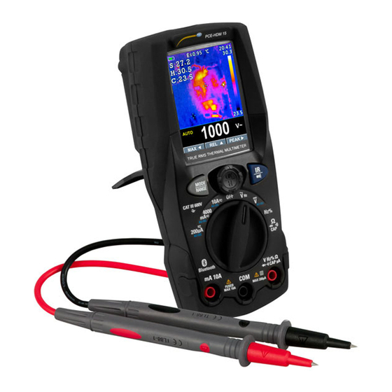
- Page 1 User Manual Thermal Imager PCE-HDM 20 User manuals in various languages (français, italiano, español, português, nederlands, türk, polski, русский, 中文) can be found by using our product search on: www.pce-instruments.com Last change: 24 July 2018 v1.0...
-
Page 2: Table Of Contents
3.16 Capturing Minimum and Maximum Values ..............13 3.17 Relative Values .......................13 3.18 Capturing Peak Values ....................14 3.19 Non-Contact AC Voltage Detector (100 to 1000V AC) .............14 Thermal imager and DMM operation ..........15 Thermal imager description .....................15 Using the thermal imager ....................16 © PCE Instruments... - Page 3 Bluetooth connect ......................20 Time/date ........................21 5.10 Photo ..........................21 5.11 Sys Info ...........................22 5.12 Factory Set ........................22 5.13 Record measurements ....................22 Image Browser ..................25 Technical specifications ..............26 Delivery contents ................30 Warranty ....................30 10 Disposal ....................30 © PCE Instruments...
-
Page 4: Safety Notes
Please read this manual carefully and completely before you use the device for the first time. The device may only be used by qualified personnel and repaired by PCE Instruments personnel. Damage or injuries caused by non-observance of the manual are excluded from our liability and not covered by our warranty. -
Page 5: Safety Symbols
We expressly point to our general guarantee terms which can be found in our general terms of business. If you have any questions please contact PCE Instruments. The contact details can be found at the end of this manual. Safety symbols... -
Page 6: Device Description
10-Positive (+) probe input jack for all inputs except A and mA 11-Thermal mode/Light button 12-Hold/Capture button Back 1 -No-slip slope 2 -Thermal imager lens 3 -Lens cover 4 -Work light 5 -Laser 6 -Stand 7 -Battery cover lock © PCE Instruments... -
Page 7: Keys
4. Analogue bar graph 5. Functions of navigation keys 6. System time 7. Measuring unit IR + DMM mode 8. SD card 9. Temperature reading 10. Automatic/Manual mode 11. Temperature unit 12. IR image 13. Measuring unit 14. Reading © PCE Instruments... -
Page 8: Rotary Switch
Frequency and duty measurements Resistance, diode test, capacitance and continuity measurements Temperature measurements AC, DC and AC+DC amps measurements AC, DC and AC+DC milliamps measurements AC, DC and AC+DC microampere measurements up to 6,000 μA Flexible coils current © PCE Instruments... -
Page 9: Dmm Measurement And Setup
• Insert the black test lead banana plug into the negative COM jack. Insert the red test lead banana plug into the positive V jack. • Press the MODE key to switch the V AC+DC voltage functions. • Read the AC+DC voltage in the display. © PCE Instruments... -
Page 10: Ac Voltage Measurements
COM jack. Insert the red test lead banana plug into the positive V jack. • Read the frequency in the display. • Press the MODE key to switch the duty functions. • Read the duty in the display. © PCE Instruments... -
Page 11: Resistance Measurements
• Press the MODE key to switch the continuity functions. • If the resistance is less than approx.. 50 Ω, the audible signal will sound. If the circuit is open, the display will indicate “OL”. © PCE Instruments... -
Page 12: Diode Test
• Insert the black test lead banana plug into the negative COM jack. Insert the red test lead banana plug into the positive V jack. • Press the MODE key to switch the capacitance functions. • Read the capacitance value in the display. © PCE Instruments... -
Page 13: Temperature Measurements
• Insert the black test lead banana plug into the negative COM jack. Insert the red test lead banana plug into the positive V jack. • Read the current in the display. • Press the MODE key to switch the AC ,DC and AC+DC current. • Press the RANGE key to switch range:1000mA,10A,30A,40A,100A,300A,400A,1000A,3000A. © PCE Instruments... -
Page 14: Dc Current Measurements
10 A position and insert the red test lead banana plug into the 10 A jack. • Press the MODE button to indicate the display. • Read the current in the display. © PCE Instruments... -
Page 15: Ac+Dc Current Measurements
If a reading is higher than the maximum measurable value, the indication “O.L” appears on the display. Press and hold the RANGE key for more than 1 second to exit manual mode and restore Auto Range mode. © PCE Instruments... -
Page 16: Hold Mode
MAX MIN function. 3.17 Relative Values To activate the relative mode, press the soft key labelled ▲. If the multimeter is already in the relative function, pressing ▲ causes the meter to turn off relative mode. © PCE Instruments... -
Page 17: Capturing Peak Values
Static electricity and other sources of electrical energy may randomly activate the detector. This is normal operation. The detector only activates the indicator light when AC voltage is present. It does not indicate the voltage level on the LCD. © PCE Instruments... -
Page 18: Thermal Imager And Dmm Operation
16. Unit 17. Lowest temperature reading shown on thermal scale 18. Thermal scale - the lighter the colour, the warmer the temperature; the darker the colour, the cooler the temperature 19. Highest temperature reading shown on thermal scale © PCE Instruments... -
Page 19: Using The Thermal Imager
D:S ( = 1/ IFOV ) is the spot size needed to provide an accurate temperature measure. Typically, is 2 to 3 times smaller than D:S , which means the temperature measurement measure theoretical area of the target need to be 2 to 3 times larger than that determined by the calculated theoretical D:S. © PCE Instruments... -
Page 20: Using The Multimeter With The Thermal Imager
• Press RIGHT/MENU button to enter the submenu or set focus on the currently selected item. Press LEFT button to return to the previous menu. • If you want to exit the settings menus, press MODE/RANGE/HOLD/IR button or press LEFT button in root menu. © PCE Instruments... -
Page 21: Settings Details
Press RIGHT/MENU button to set focus on this option. In focus state, use UP /DOWN button to increase or decrease emissivity value, use LEFT/RIGHT/MENU button to exit focus state. The available range is 0.01 to 0.99 in 0.01 steps. © PCE Instruments... -
Page 22: Language
100% to 10% in 10% steps. • Auto Off: Press RIGHT/MENU button to set focus on this option. In focus state, use UP/DOWN button to choose the time period after which the meter enters sleep mode. © PCE Instruments... -
Page 23: Bluetooth Connect
1.Turn on the Bluetooth function on the instrument. 2.Turn on the Bluetooth of smartphone, press the icon Thermview+ and enter into the home interface. Then press Connect Device icon on the Home interface, Bluetooth device name will appear. © PCE Instruments... -
Page 24: Time/Date
In this menu, year, month, day, hour, minute and time format can be set. The changes take effect after exiting settings menus. 5.10 Photo Press RIGHT/MENU button to enter photo menu. Two options are available: Photo Review and Delete Photo. © PCE Instruments... -
Page 25: Sys Info
With a measurement on the display (Fig130), press Button key Menu to enter the instrument’s general menu (Fig131). The screen is shown on the display. Press the Button ▲ or ▼ key to select Record Item. Press the Button ▶ Enter Record Menu (Fig132). © PCE Instruments... - Page 26 In Record Menu. Press the Button ▲ or ▼ key to select Start record Item. Press the Button ▶ Enter Save Record measurement (Fig135). In Save Record measurement, Press the Button ▶ to stop record and press the Button ▲ Save. Fig 135 © PCE Instruments...
- Page 27 X1 for at least 10 measuring points, X2 for at least 20 measuring points, X3 for at least 40 measuring points and so on for maximum 6 zooming operations. Fig138 © PCE Instruments...
-
Page 28: Image Browser
Press LEFT/RIGHT button to select previous or next picture. Press any other keys to exit Image Browser mode. 1. LEFT key instruction 2. Currently displayed picture's file name. 3. RIGHT key instruction 4. Picture display area © PCE Instruments... -
Page 29: Technical Specifications
-20 ... 60°C / -4 ... 140°F, <80% r.H. Maximum operating height 2000 m / 2187 yd Dimensions 175 x 85 x 55 mm / 6.9 x 3.3 x 2.1 in Weight 540 g / 1 lb 3oz © PCE Instruments... - Page 30 AC+ DC TRMS Voltage Range Resolution Accuracy (50 Input Protection Hz … 1 kHz) impedance against overcharge 6.000 V 0.001 V 60.00 V 0.01 V ±(2.4 % reading 1000 VDC/AC >10 MΩ 600.0 V 0.1 V +20 dgt) 1000 V © PCE Instruments...
- Page 31 + 10 dgt) 6.000 kΩ 0.001 kΩ 60.00 kΩ 0.01 kΩ ±(0.5 % reading 1000 VDC/AC >50 Ω 600.0 kΩ 0.1 kΩ + 5 dgt) 6.000 MΩ 0.001 MΩ 60.00 MΩ 0.01 MΩ ±(2.5 % reading + 10 dgt) © PCE Instruments...
- Page 32 -40.0 … 600.0 °F 0.1 °F ±(1.5 % rdg+ 5.4 °F) 600 … 1800 °F 1 °F (*) Instrument accuracy without probe; specified accuracy with stable environmental temperature at ±1 °C. For long-lasting measurements, reading increases by 2 °C. © PCE Instruments...
-
Page 33: Delivery Contents
For countries outside the EU, batteries and devices should be disposed of in accordance with your local waste regulations. If you have any questions, please contact PCE Instruments. © PCE Instruments... - Page 34 PCE Instruments contact information Germany France Spain PCE Deutschland GmbH PCE Instruments France EURL PCE Ibérica S.L. Im Langel 4 23, rue de Strasbourg Calle Mayor, 53 D-59872 Meschede 67250 SOULTZ-SOUS-FORETS 02500 Tobarra (Albacete) Deutschland France España Tel.: +49 (0) 2903 976 99 0 Téléphone: +33 (0) 972 3537 17...
Need help?
Do you have a question about the PCE-HDM 20 and is the answer not in the manual?
Questions and answers