Table of Contents
Advertisement
Quick Links
PCE Americas Inc.
PCE Instruments UK Ltd.
711 Commerce Way
Units 12/13
Suite 8
Southpoint Business Park
Jupiter
Ensign way
FL-33458
Hampshire / Southampton
USA
United Kingdom, SO31 4RF
From outside US: +1
From outside UK: +44
Tel: (561) 320-9162
Tel: (0) 2380 98703 0
Fax: (561) 320-9176
Fax: (0) 2380 98703 9
info@pce-americas.com
info@pce-instruments.com
www.pce-instruments.com/english
www.pce-instruments.com
Manual
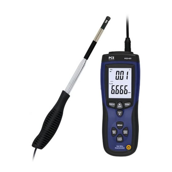
HVAC Meter PCE-423
Version 1.0
Date of creation: 10.02.2015
Date of last change: 17.06.2015
Advertisement
Table of Contents

Related Manuals for PCE Instruments PCE-423


Summary of Contents for PCE Instruments PCE-423
- Page 1 PCE Americas Inc. PCE Instruments UK Ltd. 711 Commerce Way Units 12/13 Suite 8 Southpoint Business Park Jupiter Ensign way FL-33458 Hampshire / Southampton United Kingdom, SO31 4RF From outside US: +1 From outside UK: +44 Tel: (561) 320-9162 Tel: (0) 2380 98703 0...
-
Page 2: Table Of Contents
Setup ........................10 Set the unit of the cross-sectional area (UNIT) ..............10 Adjust the value of the cross-sectional area (AREA) ..............12 Activate/deactivate the auto shut-off function (SLP)...............12 Software ......................... 13 Contact ........................14 PCE Instruments UK ......................14 PCE Americas ........................14... -
Page 3: Introduction
1 m. Both the USB cable and the software (included in the delivery) allow to connect the PCE-423 anemometer to a PC or laptop to transfer data continuously. Data can be stored in either txt or csv format for further analysis. -
Page 4: Specification
Dimensions 210 x 75 x 50 mm Weight 280 g Contents of delivery 1 x anemometer PCE-423 with telescopic probe 1 x software 1 x USB data cable 1 x mains adapter 1 x 9 V battery 1 x instruction manual... -
Page 5: System Description
Manual System description Display Low battery indication Main display; shows air velocity, saved data or time Measuring unit air velocity (m/s; ft/min; km/h; MPH; knots) Parameters secondary display: air flow (FLOW), air velocity (VEL), temperature (TEMP) or cross- sectional area (AREA) Secondary display;... -
Page 6: Buttons
Manual Buttons Button Function Turn the device on / off Freeze/unfreeze the current reading on the display (Hold) Press and hold to adjust the zero point (Zero) Enter a folder in setup menu Confirm an adjustment ... - Page 7 Manual Protection ring in upper position 5. Move the protection ring to the lower position (Fig. 2). Use the telescopic stick (Fig. 3) to adjust the sensor to the desired length. Remember to carefully insert the sensor cable into the telescopic tube when extending it, to prevent damage to the cable.
- Page 8 Manual Flow rate sensor flow direction...
-
Page 9: Measuring Functions
Manual Measuring functions 5.2.1 Averaging over a certain amount of readings Press and the current measurement value will appear on the secondary display. By means of the key you can change the measuring unit. To include this value in the calculation, press . -
Page 10: Exchange The Battery
Manual To replace the battery To replace the battery, make sure that the device is turned off. Now move the cover of the battery compartment downwards, while you push the mark on the cover. After that, you can carefully remove the cover and remove the battery by releasing it carefully from the plug-in connectors. - Page 11 Manual...
-
Page 12: Adjust The Value Of The Cross-Sectional Area (Area)
Manual Adjust the value of the cross-sectional area (AREA) To access the adjustment screen of the cross-sectional area, use until the display indicates “AREA”, the unit and the actual value of the cross-sectional area (Fig. 3). Then press confirm. The digits on the screen start to flash. Now you can set the decimal point by using to navigate through the digits. -
Page 13: Software
Manual Software First, please install the software and the USB driver “CP2102 USB to UART Bridge Controller” from the CD-ROM. If there are problems with the installation, you can find the driver installer “CP210xVCPInstaller.exe” in the folder “driver” on the CD. ... -
Page 14: Contact
Contact If you have any questions about our range of products or measuring instruments please contact PCE Instruments. PCE Instruments UK By post: PCE Instruments UK Ltd. Units 12/13 Southpoint Business Park Ensign Way, Southampton Hampshire United Kingdom, SO31 4RF...
Need help?
Do you have a question about the PCE-423 and is the answer not in the manual?
Questions and answers