Advertisement
Available languages
Available languages
Quick Links
Advertisement
Chapters

Related Manuals for PCE Instruments PCE-428


Summary of Contents for PCE Instruments PCE-428
- Page 1 Bedienungsanleitung PCE-428, PCE-430, PCE-432 Schallpegelmessgeräte User manuals in various languages (English, français, italiano, español, português, nederlands, türk, polski, русский, 中文) can be downloaded here: www.pce-instruments.com Letzte Änderung: 11. März 2021 v1.0 © PCE Instruments...
-
Page 2: Table Of Contents
Bedeutung der Bildschirmanzeige / Symbole ..............14 Bildschirm im Pegelmessmodus ..................15 Bildschirm im 1/1-Oktavmodus ..................18 Bildschirm im 1/3-Oktavmodus ..................19 Bedienung und Menüeinstellungen ..........21 Funktion ..........................22 Kalibrierung ........................22 Messung .........................26 Setup ..........................35 Sprache ..........................45 Ausgang ..........................46 Werkseinstellungen ......................47 © PCE Instruments... - Page 3 13 Typischer Frequenzgang und entsprechende Obergrenze .... 64 14 Technische Daten des 1/1-Oktavbandfilters ........65 15 Technische Daten des 1/3-Oktavbandfilters ........66 16 Mittenfrequenzen für 1/1- und 1/3-Oktavbandfilter ......69 17 Garantie ....................70 18 Entsorgung ..................70 © PCE Instruments...
-
Page 5: Sicherheitsinformationen
Für Druckfehler und inhaltliche Irrtümer in dieser Anleitung übernehmen wir keine Haftung. Wir weisen ausdrücklich auf unsere allgemeinen Gewährleistungsbedingungen hin, die Sie in unseren Allgemeinen Geschäftsbedingungen finden. Bei Fragen kontaktieren Sie bitte die PCE Deutschland GmbH. Die Kontaktdaten finden Sie am Ende dieser Anleitung. © PCE Instruments... -
Page 6: Einführung
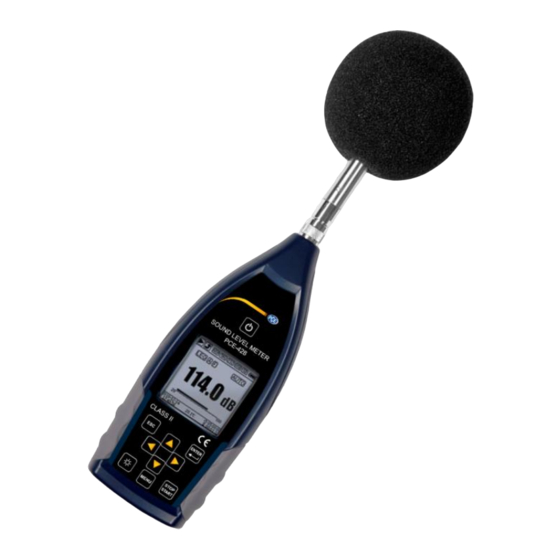
Die neuen digitalen Schallpegelmessgeräte PCE-428 / PCE-430 / PCE-432 sind mit einem hochgenauen 24 Bit AD-Wandler ausgestattet und somit vielseitig einsetzbar, z. B. zum Messen von Umgebungslärm, Verkehrslärm oder Lärm im industriellen Bereich. Beim PCE-430 und PCE-432 handelt es sich um Klasse 1-Geräte, das PCE-428 ist ein Klasse 2-Gerät. Eigenschaften Normen: IEC 61672-1:2013, ANSI S1.4-1983 und ANSI S1.43-1997... -
Page 7: Spezifikationen
Oktave: 30 … 136 dB Oktave: 33 … 136 dB 123 dB (13 … 136 dB(A)) 122 dB (14 … 136 dB(A)) Dynamikbereich 47 … 139 dB 50 … 139 dB Peak-C-Bereich Elektrischer Eingang Maximale Eingangsspannung 5 V (7,07 VSpitze) © PCE Instruments... - Page 8 Gewicht ca. 620 g (inkl. Batterien) Hinweise: Für PCE-428 Ergebnis außerhalb des Bereichs 20 Hz … 12,5 kHz aufgrund des Mikrofonfrequenzgangs für Messgeräte der Klasse 2 ignorieren. Die Daten wurden mit einem Mikrofon mit einer Empfindlichkeit von 40 mV/Pa gemessen.
-
Page 9: Lieferumfang
Lieferumfang 1 x Schallpegelmessgerät PCE-428, PCE-430 oder PCE-432 1 x 1/2" Messmikrofon Klasse 2 (PCE-428) bzw. Klasse 1 (PCE-430 / PCE-432) 1 x Windgeräuschunterdrücker (Schaumball) 1 x USB Schnittstellenkabel 1 x Netzteil 1 x Tragekoffer 1 x ISO-Kalibrierzertifikat 1 x Bedienungsanleitung Die Software kann in unserem Downloadbereich heruntergeladen werden: https://www.pce-... -
Page 10: Systembeschreibung
Systembeschreibung Gerät LCD mit Hintergrundbeleuchtung RS-232 Schnittstelle Mikrofon und Vorverstärker AC Ausgang LED Anzeige DC Ausgang Rutschfester Gummischutz Trigger LR6/AA/AM3 Akku Ladebuchse Anschlussgewinde Micro SD Abdeckungsverriegelung Mini USB links ◄: entriegeln rechts ►: verriegeln © PCE Instruments... -
Page 11: Daten- Und Stromversorgungsanschluss
Trigger-Eingang mit Standardkopfhörerbuchse 3,5 mm. Weitere Details dazu finden Sie unter 7.4.4 Trigger. DC OUT: Gleichspannungsausgang mit Standardkopfhörerbuchse 3,5 mm. Weitere Details finden Sie unter 7.6.2 Gleichspannungsausgang. AC OUT: Wechselspannungsausgang mit Standardkopfhörerbuchse 3,5 mm. Weitere Details dazu finden Sie unter 7.6.1 Wechselspannungsausgang. © PCE Instruments... -
Page 12: Bedienfeld
Bedienfeld Ein / Aus Taste Abbruchtaste Pfeiltasten Taste Hintergrundbeleuchtung Menütaste Stopp / Start Taste Eingabetaste © PCE Instruments... - Page 13 Pfeiltaste Ab: zur Auswahl einer Option oder zur Änderung eines Wertes Pfeiltaste Links: zur Auswahl einer Option, zur Änderung eines Wertes oder Wechsel zur nächsten Seite Pfeiltaste Rechts: Rechtspfeiltaste, zur Auswahl einer Option, zur Änderung eines Wertes oder Wechsel zur nächsten Seite Menütaste: Zum Aufrufen des Menüs © PCE Instruments...
-
Page 14: Mikrofonanschluss
Gehäuse montiert). Der TNC-Anschluss ist ein Koaxialverbinder mit Gewinde. Die Messgeräte PCE-430 und PCE-432 sind mit einem Mikrofon der Klasse 1 ausgestattet, das Messgerät PCE-428 mit einem Mikrofon der Klasse 2: PCE-428-MIC: Vorpolarisiertes Messmikrofon 1/2”, Klasse 1, Empfindlichkeit: 40 mV/Pa, Frequenzbereich: 3 Hz …... -
Page 15: Windschutz
Umgebung nicht mit Wind zu rechnen ist (beispielsweise bei Messungen in Innenräumen). Drücken Sie den Windschutz entsprechend der oberen Abbildung fest bis zum Anschlag auf das Mikrofon. Weitere Details für Korrekturen des Windschutzes im Freien finden Sie unter 12.2 Korrekturen des Windschutzes im Freien. © PCE Instruments... -
Page 16: Batterie
Richten Sie sich beim Einlegen und beim Austausch der Batterien nach der folgenden Abbildung: Schieben Sie die Abdeckungsverriegelung nach links, um die Batteriefachabdeckung zu entriegeln. Nehmen Sie die Batteriefachabdeckung ab. Wechseln Sie die Batterien und verschließen verriegeln Sie die Batteriefachabdeckung wieder. © PCE Instruments... -
Page 17: Gps (Nur Pce-432)
Messung Seite 1, anpassbare Messung Seite 2, GPS-Seite 1 und GPS-Seite 2. Die 1/1-Oktavmessung hat 4-6 Bildschirme: Oktavhistogramm, Oktavtabelle Seite 1–3. Nur PCE-432: GPS-Seite 1 und GPS-Seite 2. Die 1/3-Oktavmessung hat 5-7 Bildschirme: Oktavhistogramm, Oktavtabelle Seite 1–4. Nur PCE-432: GPS-Seite 1 und GPS-Seite 2. © PCE Instruments... -
Page 18: Bedeutung Der Bildschirmanzeige / Symbole
Timer aktiviert ist und immer wieder gestartet wird. MicroSD-Status Wird bei Speicherung der Daten angezeigt Einschaltstatus Symbole von links nach rechts: externe Stromversorgung, Batteriestromversorgung (mit Spannungsanzeige) und USB- Stromversorgung Berechnete Parameter Filterstatus Detektorstatus Bereichsstatus Einzelbereich, Anzeige Auto © PCE Instruments... -
Page 19: Bildschirm Im Pegelmessmodus
Datengruppe der 3 Profile. Drücken Sie die Pfeiltasten aufwärts und abwärts, um zwischen den 3 Profilen umzuschalten. 3 Profile Anzeige Daten entsprechenden Messmodus des Filters und des Detektors der Profilmessung gleichzeitig. Die Daten der 3 Profile können in einer SWN-Datei gespeichert werden. © PCE Instruments... - Page 20 Minuten) lassen sich anpassen. Drücken Sie die Abbruchtaste, um den Bildschirm zu löschen und die Kurve neu anzuzeigen. Anpassbare Messseite 1 Der Benutzer kann die Parameter der 14 Messsätze einstellen. In diesem Bildschirm lassen sich die ersten 7 Messsätze anzeigen. © PCE Instruments...
- Page 21 Positionsbestimmung Bestimmung Signalrauschabstands aller sichtbaren Satelliten (0 … 99 dB). Hinweis: Die Anzahl der sichtbaren Satelliten kann größer sein als die Anzahl der Satelliten für die Positionsbestimmung, weil manche Satelliten für die Positionsbestimmung nicht verfügbar sind. © PCE Instruments...
-
Page 22: Bildschirm Im 1/1-Oktavmodus
Anzeige der Messdaten von 8 Hz … 16 kHz. Die LED leuchtet rot und erscheint, wenn die Daten den Schwellenwert übersteigen. Oktavtabelle Seite 2 Anzeige der Messdaten von 1 kHz … 16 kHz. Die LED leuchtet rot und erscheint, wenn die Daten den Schwellenwert übersteigen. © PCE Instruments... -
Page 23: Bildschirm Im 1/3-Oktavmodus
Schwellenwert definieren. Die LED leuchtet rot, wenn die Daten den Schwellenwert übersteigen. Oktavtabelle Seite 1 Anzeige der Messdaten von 6,3 Hz … 80 kHz. Die LED leuchtet rot und der dB-Wert erscheint in umgekehrten Farben, wenn Daten Schwellenwert übersteigen. © PCE Instruments... - Page 24 Farben, wenn Daten Schwellenwert übersteigen. Oktavtabelle Seite 4 Anzeige der Messdaten von LAeq, LBeq, LCeq sowie LZeq. Die LED leuchtet rot und erscheint, wenn die Daten den Schwellenwert übersteigen. © PCE Instruments...
-
Page 25: Bedienung Und Menüeinstellungen
Bedienung und Menüeinstellungen Drücken Sie die Menütaste, um das nächste Menü aufzurufen. Alle Messparameter können im Menü eingestellt werden. Menübaum © PCE Instruments... -
Page 26: Funktion
Der Benutzer muss daher vor der Messung mindestens eine Kalibrierung durchführen. Es gibt zwei Kalibrierverfahren: durch Messung und mit Kalibrierfaktor. Zur Kalibrierung mit einem Schallkalibrator sollte Verfahren durch Messung verwendet werden. Kalibrierverfahren Kalibrierfaktor erlaubt manuelle Anpassung Kalibrierfaktors durch den Benutzer. © PCE Instruments... - Page 27 Sens die Empfindlichkeit des Mikrofons in mV/Pa; Offset der Kalibrierfaktor in Dezibel (dB). Dieser Wert ist das Kalibrierergebnis mit dem Verfahren „Durch Messung“ bei einem Signal von 40 mV. Dieser Offset ist die geräteeigene Abweichung, die bei jedem Schallpegelmessgerät unterschiedlich ist. © PCE Instruments...
- Page 28 (1) Führen Sie das Mikrofon bis zum Anschlag in den Hohlraum des Kalibrators ein. Das Mikrofon muss fest sitzen. (2) Schalten Sie dann den Kalibrator zu und stellen Sie einen konstanten Schallpegel ein (z. B. 94 dB). © PCE Instruments...
- Page 29 Drücken Sie die Eingabetaste, um die Ergebnisse zu übernehmen. (6) Rufen Sie wieder den Hauptbildschirm auf und drücken Sie die Stop / Start Taste, um die Messung zu starten. Das aktuelle Messergebnis in diesem Beispiel sollte 93,8 dB betragen, wenn der Kalibrator einwandfrei ist. © PCE Instruments...
-
Page 30: Messung
Option auszuwählen: Unendlich, 1 … 59 s, 1 … 59 min, 1 … 24 h. Wiederholung: Die Zahl der Wiederholungen in einer Messung. Gesamtmesszeit = Integralzeitraum x Wiederholung. Drücken Sie die Pfeiltasten links und rechts, um eine der folgenden Optionen auszuwählen: Inf, 1 … 9999. © PCE Instruments... - Page 31 (des Integralzeitraums) werden in der SWN/OCT-Datei als eine Zeile gespeichert. Die CSD-Datei speichert nur Momentandaten ohne Integration. Sobald der CSD-Protokollschritt erreicht ist, werden die 14 Gruppendaten der anpassbaren Messung als Zeile der CSD-Datei wie eine Momentaufnahme gespeichert. © PCE Instruments...
- Page 32 Bereich, Schallpegelmessgerät anzeigen kann. Das Messergebnis in der Nähe des Eigenrauschens muss nicht linear betrachtet werden. Peak C-Bereich: Der Peak-C-Bereich ist der lineare Bereich der Peak-C-Messung. Die Peak-C-Messung in diesem Bereich kann als korrekt betrachtet werden. © PCE Instruments...
- Page 33 Mit dieser Option definieren Sie, welche Daten in der SWN-Datei gespeichert werden sollen, da die Datenquelle der SWN-Datei Profil 1–3 ist. Diese Option hat keine Beziehung zur Bildschirmanzeige. Drücken Sie die Pfeiltasten links und rechts, um eine der folgenden Optionen auszuwählen: LEQ, PEAK, MAX oder MIN. © PCE Instruments...
- Page 34 7.3.7 Statistik Die Datenquelle für die „Statistik“ ist fest auf SPL eingestellt. Der Benutzer kann diese Einstellung nicht ändern. Der Benutzer kann jedoch den Filter und den Detektor für SPL, sowie den Statistikwert über dieses Menü definieren. © PCE Instruments...
- Page 35 Mit den Pfeiltasten links und rechts können Sie die Datenquelle des Zeitverlaufs einstellen: Profil 1, Profil 2, Profil 3. Dauer: Mit den Pfeiltasten links und rechts können Sie die Zeitachse des Zeitverlaufs einstellen: 1 Minute, 2 Minuten, 10 Minuten. © PCE Instruments...
- Page 36 Messungen definieren können. Mit den Pfeiltasten links und rechts können Sie die Option auswählen und mit der Eingabetaste die nächste Menüebene aufrufen. Mit den Pfeiltasten links und rechts können Sie für jede Gruppe anpassbarer Messungen eine Option einstellen: Filter, Detektor und Modus. © PCE Instruments...
- Page 37 (Integralzeitdauer x Wiederholung) + 5 s, da für den Timer bei ausgelöster Messung eine feste Verzögerung von 3 s eingestellt ist und vor der Verzögerung 2 weitere Sekunden benötigt werden. Sie dürfen die Einstellungen nicht ändern, wenn der Timer läuft, da dieser sonst nicht funktioniert. © PCE Instruments...
- Page 38 Stellen Sie als Starttag das gewünschte Datum ein. Stellen Sie als Startzeit 00:00 ein. Das ist die Zeit, zu der die Messung erstmals ausgelöst wird. Stellen Sie das Wiederholungsintervall auf 1 Stunde ein, so dass die Messung zu jeder Stunde ausgelöst wird. © PCE Instruments...
-
Page 39: Setup
Drücken Sie zur Auswahl die Pfeiltasten aufwärts und abwärts. 7.4.2 Hintergrundbeleuchtung Schalldruck-Messgerät schaltet Displaybeleuchtung automatisch ab, um den Stromverbrauch reduzieren Batterie schonen. Menü „Hinterlgrundbel.“ können Abschaltung aktivieren bzw. deaktivieren und die Verzögerungszeit für die Hinterleuchtung ändern. Drücken Auswahl Pfeiltasten aufwärts und abwärts. © PCE Instruments... - Page 40 Triggereingang befindet sich an der Unterseite des Geräts (Kopfhörerbuchse 3,5 mm). Die Messung wird durch eine Verbindung der Signalleitung mit Masse gestartet und durch deren Unterbrechung gestoppt. Beachten Sie, dass bei Aktivierung der Trigger-Funktion die Start/Stopp-Schaltfläche nicht verfügbar ist. © PCE Instruments...
- Page 41 Spannung der RTC-Batterie zu gering ist. Lösen Sie dazu die Schrauben Rückseite Schallmessgeräts, damit Sie den Deckel abnehmen können. Die RTC-Batterie befindet sich auf der Platine wie in der folgenden Abbildung dargestellt. Die Batterie ist eine Knopfzelle CR-1220. © PCE Instruments...
- Page 42 Fehler von 2 ppm (maximaler Fehler 3 ppm) kalibriert. Die Ungenauigkeit bei der Zeit liegt bei Zimmertemperatur unter 10 ppm (<26 Sekunden innerhalb von 30 Tagen). Der maximale Zeitfehler betrug bei internen Prüfungen bei 25 °C ca. 5 … 8 Sekunden. © PCE Instruments...
- Page 43 Sie die Optionen für den seriellen Anschluss einstellen, siehe dazu Datenübertragungsprotokoll RS-232 Modus der RS-232 Schnittstelle: Optionen RS-232: Remote, Drucker. Wählen Sie anhand der Pfeiltasten links und rechts „Remote“ aus. Das Schallpegelmessgerät kann über den Anschluss RS-232 im Remote-Modus Daten senden und steuern. © PCE Instruments...
- Page 44 Mit dem „Dateimanager“ können Sie die gespeicherte SWN-, OCT- und CSD-Datei verwalten. Die Ziffernanzeige auf der rechten Seite jeder Zeile ist der Dateizähler für jeden Dateityp. Mit den Pfeiltasten aufwärts und abwärts können Sie die Option auswählen Eingabetaste nächste Menüebene aufrufen. © PCE Instruments...
- Page 45 Menü für die SWN-Datei. Im Menü „CSD-Datei“ können Sie die CSD-Datei löschen oder auslesen. Anhand der Pfeiltasten aufwärts und abwärts können Sie den Cursor zwischen „Auswählen“ und „Option“ verschieben. Das Löschen erfolgt genauso wie im Menü der SWN-Datei. © PCE Instruments...
- Page 46 Der Hardware-Schalter für den Modus befindet sich im Batteriefach. Er ist nach dem Entfernen der Batterien leicht zugänglich. Schieben Sie den Schalter mit einer Zange oder einem Stift in die Stellung für "Boot" oder "Normal". ACHTUNG: Vermeiden Sie vor der Bedienung elektrostatische Aufladungen, da dieser Bereich sehr empfindlich dafür ist. © PCE Instruments...
- Page 47 Das Gerät fragt immer, welcher Modus bei der Verbindung des USB-Kabels mit dem Computer gewählt werden soll. Entscheiden Sie möglichst zügig, welche Option Sie verwenden möchten, da sonst der Computer das Schallpegelmessgerät aufgrund der Zeitüberschreitung nicht erkennt. © PCE Instruments...
- Page 48 Mit der „Setup-Vorlage“ speichern Sie fünf Benutzergruppen-Einstellungsparameter des Schallpegelmessgeräts für verschiedene Anwendungen. Hinweis: Die Vorlage verändert nicht den Kalibrierfaktor. Versuchen Sie nicht, die Vorlage der alten Version in die Firmware der neuen Version zu laden, da bestimmte Modifikationen Vorlagenformats vorhanden sein könnten. © PCE Instruments...
-
Page 49: Sprache
HWID (Hardware-ID) des Schallpegelmessgeräts Sprache Das Schallpegelmessgerät unterstützt sechs Sprachen: Deutsch, Englisch, Chinesisch, Portugiesisch, Spanisch und Französisch. Mit den Pfeiltasten aufwärts und abwärts können Sie die entsprechende „Sprache“ auswählen und mit der Eingabetaste die Einstellung speichern. © PCE Instruments... -
Page 50: Ausgang
Ausgang z. B. 938 mV aus. Diese Option wird zum Filtern oder zur Mittelwertbildung des Ausgangssignals empfohlen, um Rauschen auszublenden. „Gleichspannungsausgang Schallpegelmessgeräts“ kann Signalausgang für den Pegelmessmodus einstellen. Drücken Sie zur Auswahl die Pfeiltasten. Filter: A, B, C, Z (flach) Detektor: Schnell, Langsam, Imp. Modus: SPL, LEQ, Peak © PCE Instruments... -
Page 51: Werkseinstellungen
(Nein) auswählen oder die Abbruchtaste drücken, wird das Zurücksetzen abgebrochen. Datenübertragungsprotokoll RS-232 Die Schallpegelmessgeräte PCE-428 / PCE-430 / PCE-432 sind mit einer seriellen RS-232 Schnittstelle ausgestattet. Der Benutzer kann die Konfiguration des Schallpegelmessgeräts über die serielle Schnittstelle modifizieren, das Schallpegelmessgerät starten und stoppen, die aktuellen Messwertparameter abfragen und die Ergebnisse weiterverarbeiten. -
Page 52: Übertragungsprotokoll
Befehl oder Daten <ETX> <CR> <LF> 8.2.1 Start und Stopp der blockweisen Übertragung Ein Befehlsblock oder Antwortblock enthält Startzeichen, End-Zeichen und sonstige Steuerzeichen wie in der folgenden Tabelle: Name Bedeutung <STX> Startzeichen <ETX> Stoppzeichen <CR> Wagenrückläufe <LF> Zeilenvorschub © PCE Instruments... - Page 53 Anweisung aus. Auf diese Weise können Sie das Senden des Anweisungsblocks vereinfachen. Nicht empfohlen wird dieses Verfahren allerdings für Übertragungen über große Entfernungen, weil BCC die einzige Möglichkeit ist, die Zuverlässigkeit der Datenübertragung zu garantieren. Name Bedeutung 01H bis FFH XOR-Prüfsumme Prüfsumme ignorieren © PCE Instruments...
- Page 54 Hierbei ist: ATTR=<NAK>. Der Fehlercode belegt 4 Bytes. Alle möglichen Fehlercodes sind in der folgenden Tabelle aufgelistet. Die Bedeutung der Fehlercodes ist im nächsten Abschnitt näher beschrieben. Fehlercode Bedeutung 0001H Anweisungsfehler 0002H Parameterfehler 0003H Im aktuellen Status nicht verfügbar © PCE Instruments...
- Page 55 8.2.6 Wiederherstellung nach Übertragungsfehlern Bei der Übertragung des Befehlsblocks oder Antwortblocks können verschiedene Fehler auftreten. Im Folgenden wird beschrieben, wie das Schallpegelmessgerät mit Fehlern umgeht und den Ausgangszustand wieder herstellt. (1) Blockübertragung nicht abgeschlossen © PCE Instruments...
- Page 56 Befehle auf die Daten und Parameter jedes einzelnen Schallpegelmessgeräts zugreifen. Dabei sollten Sie Folgendes beachten: - In einem Netzwerk dürfen Schallpegelmessgeräte niemals die gleiche ID besitzen. - Der Benutzer darf keinen Befehl per Broadcast versenden, der beliebige Daten zurück liefert. © PCE Instruments...
-
Page 57: Anweisungen
Einstellanweisungen definieren Messparameter Systemparameter für Schallpegelmessgerät. Abfragebefehle fragen die Parameter und Daten des Schallpegelmessgeräts ab. Es gibt drei Situationen, in denen Anweisungen an das Schallpegelmessgerät gesendet werden: - Einstellanweisung (ohne Antwort) - Einstellanweisungen (mit Antwort) - Abfrageanweisungen. © PCE Instruments... - Page 58 (2) Einstellanweisungen (mit Antwort): Normale Antwort: Computer Einstellanweisung Schallpegel- messgerät ACK zurück Fehlerantwort: Computer Schallpegel- Einstellanweisung messgerät NAK zurück (3) Abfragebefehl: Normale Antwort: Computer Abfrageanweisung Schallpegel- messgerät NAK zurück Fehlerantwort: Computer Abfrageanweisung Schallpegel- messgerät NAK zurück © PCE Instruments...
-
Page 59: Instandhaltung
Maximalkapazität von 4 GB. Firmware-Aktualisierung Die Firmware kann über den USB-Anschluss aktualisiert werden. Hierzu benötigen Sie Folgendes: - Ausgeschaltetes Schallpegelmessgerät PCE-428 / PCE-430 / PCE-432 (HWID P0274 oder höher) - Mini-USB-Kabel (im Lieferumfang) - Netzteil (im Lieferumfang enthalten) - Firmware für das Update... -
Page 60: Installation Usb-Treiber
Computer verbinden. 10.2 Vorgehensweise Firmware-Aktualisierung Folgen Anweisungen Firmware-Aktualisierungssoftware FlashTool Wizard Schritt für Schritt. Starten Sie den FlashTool Wizard und wählen Sie die Sprache aus. Schritt 1: Bereiten Sie die Liste für die Firmware-Aktualisierung vor. © PCE Instruments... - Page 61 Sie die MicroSD-Karte und versuchen Sie es erneut. Es gibt keine Einschränkungen für ein Upgrade oder Downgrade der Firmware. Der Benutzer kann auf jede Version aktualisieren. Wir empfehlen jedoch immer, die Vorversion der Firmware aufzubewahren. © PCE Instruments...
-
Page 62: Glossar
Schalldrucksignals während eines angegebenen Zeitintervalls und dem Quadrat des Referenzwerts LEQ ist der aktuelle Integralwert des Schallpegels bei der angegebenen Dauer. Je länger der Integralzeitraum ist, desto langsamer ändert sich LEQ. LEQ wird häufig zur Gesamtbewertung der Lärmbelastung verwendet. © PCE Instruments... - Page 63 Minimale Zeit des gewichteten Schallpegels innerhalb der angegebenen Dauer Zeitgewichteter Schallpegel der Standardabweichung innerhalb der angegebenen Dauer. SD dient zur Beschreibung des Grades der Streuungsänderungen des Schallpegels Hinweis 1: Weitere Informationen finden Sie in der Definition der Norm IEC 61672.1:2013. © PCE Instruments...
-
Page 64: Korrekturen
Korrekturen 12.1 Korrektur für typische Reflexionen vom Gehäuse des Schallpegelmessgeräts und Schallstreuung um das Mikrofon © PCE Instruments... - Page 65 *18836 -0,3 501,19 1584,9 2985,4 5623,4 10593 *19953 -0,4 Erweiterte Unsicherheiten: U=0,17 (k=2) bei <= 4 kHz, U=0,29 (k=2) bei >4 kHz Hinweis: Die mit * markierte Frequenz ist in der Norm nicht vorgeschrieben. Die exakte Frequenz © PCE Instruments...
-
Page 66: Korrekturen Des Windschutzes Im Freien
2511,9 0,41 *19953 -1,92 Erweiterte Unsicherheiten: U=0,15 (k=2) bei <= 4 kHz, U=0,21 (k=2) bei >4 kHz. Hinweis: Die mit * markierte Frequenz ist in der Norm nicht vorgeschrieben. Die exakte Frequenz finden Sie in IEC 61672-1. © PCE Instruments... -
Page 67: Korrekturen Des Elektretmikrofons
0,027 1600 0,213 5000 1,488 16000 7,956 0,034 1800 0,260 5600 1,798 18000 8,664 20000 9,272 Erweiterte Unsicherheiten: U=0,19 (k=2) bei <= 4 kHz, U=0,34 (k=2) bei 4 … 10 kHz, U=0,39 (k=2) bei >= 10 kHz. © PCE Instruments... -
Page 68: Typischer Frequenzgang Und Entsprechende Obergrenze
16 k* A-Gewichtung -39,5 -26,2 -16,2 -8,7 -3,3 +1,3 +1,2 -0,5 -9,7 [dB] B-Gewichtung -17,1 -9,4 -4,3 -1,4 -0,3 -0,5 -2,3 -11,6 [dB] C-Gewichtung -3,0 -0,8 -0,2 -0,1 -0,6 -2,4 -11,7 [dB] Hinweis *: Nicht für PCE-428 verfügbar. © PCE Instruments... -
Page 69: Technische Daten Des 1/1-Oktavbandfilters
Technische Daten des 1/1-Oktavbandfilters Der 1/1-Oktavbandfilter wurde aus einem Butterworth-Filter mit der Basis 10 entwickelt. Die technischen Daten jedes Filters sind in folgenden Abbildungen angegeben. © PCE Instruments... -
Page 70: Technische Daten Des 1/3-Oktavbandfilters
Technische Daten des 1/3-Oktavbandfilters Der 1/3-Oktavfilter wurde aus einem Butterworth-Filter mit der Basis 10 entwickelt. Die technischen Daten jedes Filters sind in folgenden Abbildungen angegeben. © PCE Instruments... - Page 71 © PCE Instruments...
- Page 72 © PCE Instruments...
-
Page 73: Mittenfrequenzen Für 1/1- Und 1/3-Oktavbandfilter
1258,9 1250 1584,9 1600 1995,3 2000 2511,9 2500 3162,3 3150 3981,1 4000 5011,9 5000 6309,6 6300 7943,3 8000 10000 10000 12589 12500 15849 16000 19953 20000 Hinweis: Die genauen Mittenfrequenz wurden bis auf 5 signifikante Ziffern berechnet. © PCE Instruments... -
Page 74: Garantie
Umsetzung ElektroG (Rücknahme Entsorgung Elektro- Elektronikaltgeräten) nehmen wir unsere Geräte zurück. Sie werden entweder bei uns wiederverwertet oder über ein Recyclingunternehmen nach gesetzlicher Vorgabe entsorgt. Alternativ können Sie Ihre Altgeräte auch an dafür vorgesehenen Sammelstellen abgeben. WEEE-Reg.-Nr.DE69278128 © PCE Instruments... - Page 75 PCE Instruments Kontaktinformationen Germany France Spain PCE Deutschland GmbH PCE Instruments France EURL PCE Ibérica S.L. Im Langel 4 23, rue de Strasbourg Calle Mayor, 53 D-59872 Meschede 67250 SOULTZ-SOUS-FORETS 02500 Tobarra (Albacete) Deutschland France España Tel.: +49 (0) 2903 976 99 0 Téléphone: +33 (0) 972 3537 17...
- Page 76 PCE Americas Inc. PCE Instruments UK Ltd. 711 Commerce Way Unit 11 Suite 8 Southpoint Business Park Jupiter Ensign way FL-33458 Hampshire / Southampton United Kingdom, SO31 4RF From outside US: +1 From outside UK: +44 Tel: (561) 320-9162 Tel: (0) 2380 98703 0...
- Page 77 PCE-428 / 430 / 432 Contents Contents ......................... 2 Appearance ........................6 Buttons of Operation ....................... 7 1. Introduction ......................... 8 1.1 General Description ....................8 1.2 Applications ......................8 1.3 Features ........................8 1.4 Function Upgrades ....................9 1.5 Spectification ......................9 1.6 Information for Periodic Tests ................
- Page 78 PCE-428 / 430 / 432 3.4 Screen of 1/3 Octave Mode ................... 26 4. Operation and Setting of the Menu ................28 4.1 Function ........................ 28 4.2 Calibration ......................29 4.2.1 Calibration by Measurement ................29 4.2.2 Calibration by Cal.Factor .................. 29 4.2.3 Conversion of Cal.Factor and Sensitivity ............
- Page 79 PCE-428 / 430 / 432 4.4.9 Boot Mode ......................45 4.4.10 USB Mode ...................... 46 4.4.11 GPS ........................ 47 4.4.12 Setup Template ....................47 4.4.13 About ......................48 4.5 Language ......................48 4.6 Output ........................48 4.6.1 AC OUT ......................48 4.6.2 DC OUT ......................
- Page 80 PCE-428 / 430 / 432 6.3 Calibration ......................97 6.4 Firmware Update ....................97 6.4.1 Install USB Driver ................... 97 6.4.2 Firmware Update Procedure ................98 6.5 Warranty ......................99 Annex 1 Glossary ....................... 100 Annex 2 Adjustments at the Calibration Check Frequency ........... 102 Annex 3 Corrections for the Typical Effects of Reflections from the Case of Sound Level Meter and Diffraction of Sound around the Microphone .........
-
Page 81: Appearance
PCE-428 / 430 / 432 Appearance... -
Page 82: Buttons Of Operation
PCE-428 / 430 / 432 Buttons of Operation LED indicator <Power> LCD Screen <Enter> <ESC> Arrow keys <▲><▼> <◄><►> <Start/Stop> <Backlight> <Menu>... -
Page 83: Introduction
PCE-428/430/432 The new are new generation octave sound level meter upgrade from base PCE-428/430/432 to meet the market demand. It fulfill the 1/1 octave requirement of IEC standard and China GB/T standard. PCE-428/430/432 is a digital sound level meter which design and manufacture by PCE . -
Page 84: Function Upgrades
PCE-428 / 430 / 432 frequency/time weighting Calculate SPL, LEQ, Max, Min, Peak, SD, SEL, E LN statistical and time history curve display User define integral period measurement, integral period up to 24h High speed ARM core with FPU (Float Point Unit) to achieve wide frequency response, large dynamic range and low noise floor ... - Page 85 PCE-428 / 430 / 432 MPA231T: 1/2” prepolarized MPA309T: 1/2” prepolarized Supplied measurement microphone, Class measurement microphone, Class Microphone 1. Sensitivity: 40mV/Pa. Frequency 2. Sensitivity: 40mV/Pa. Frequency Range: 3Hz~20kHz. Range: 20Hz~12.5kHz. Mic Interface TNC connecter with ICCP power supply (4mA) Detector / Filter Fully float-point digital signal processing (digital detector and filter)...
- Page 86 PCE-428 / 430 / 432 2, 3 Peak C Range 47dB~139dB 50dB~139dB Maximum input voltage: 5Vrms (7.07Vpeak). Input impedance of Electrical Input preamplifier: >6GΩ Range Setting Single range to cover whole dynamic range Resolution 24Bits Sampling Rate 48kHz (Sampling interval for LN: 20ms) Time History Time domain noise curve display.
-
Page 87: Information For Periodic Tests
Printer Mini thermal or dot-matrix printer, RS-232 port Note 1: Ignore the result outside 20Hz~12.5kHz for type PCE-428 alone due to microphone frequency response of Class 2. Note 2: The data was measured with 40mV/Pa microphone for PCE-430/432 and PCE-428. -
Page 88: Key Component
Class 1 microphone Microphone MP309 Class 2 microphone 1.8 Packing List 1 x sound level meter PCE-428, PCE-430 or PCE-432 1 x microphone 1 x wind noise suppressor (foam ball) 1 x USB cable 1 x power supply 1 x factory calibration certificate according to ISO 9001... -
Page 89: Packing Drawing
PCE-428 / 430 / 432 1.9 Packing Drawing ☆Note: The detail of packing items may vary to follow orders. -
Page 90: The Appearance And Operation
PCE-428 / 430 / 432 2. The Appearance and Operation PCE-428/430/432 uses the same body and the keypad layout. LCD screen, keypad and LED indicators lay on the front of instrument. 2.1 Keypad Sound level meter has 10 keys, namely: <Power>... - Page 91 PCE-428 / 430 / 432 <Start/Stop>: Start or stop the measurement. <▲>: Up arrow used to select the menu item or adjust the parameters. <▼>: Down arrow used to select the menu item or adjust the parameters. <◄>: Left arrow used to select the menu item, or adjust the parameters, or switch measure screens.
-
Page 92: Windscreen
PCE-428 / 430 / 432 Microphone and preamplifier are mounted together by thread. Unless special situation, please do not separate each other. The microphone is a precision measurement sensor, long-term exposure to high humidity or dust environment would impact microphone. -
Page 93: Data And Power Supply Connector
PCE-428 / 430 / 432 2.4 Data and Power Supply Connector There are 7 interfaces at the bottom of the sound level meter. Open the rubber cover to see these interfaces. PWR: Power connector, using the standard DC socket (2.1mm core diameter), can connect to the 7~14V 500mA external power supply. -
Page 94: Battery
PCE-428 / 430 / 432 Disk Mode. Note that the MicroSD card provides with the sound level meter has already formatted before sale. ☆Note: Keep front side (with silk screen) of MicroSD card down to insert without hot-plug. RS-232: It can be use as standard RS-232 port at Remote mode, and also can be used to connect thermal printer as Printer mode. -
Page 95: Gps
PCE-428 / 430 / 432 Turn the button to the left side to unlock the battery compartment cover. Then lift the cover to open it. Close and lock the battery compartment after change the battery. 2.6 GPS GPS antenna cover located on the top surface of sound level meter which select GPS function as option module. - Page 96 PCE-428 / 430 / 432 Satellite Ephemeris: GPS satellites orbit information. According to ephemeris, satellite positioning signal and time, the current location can be determined. Ephemeris need to download from the GPS satellites, but the download speed is very low (approx. 50bps), and vulnerable to the impact of satellite signal strength.
-
Page 97: Measurement Screen
PCE-428 / 430 / 432 3. Measurement Screen Sound level meter has three measurement modes: Level Meter, 1/1 Octave, 1/3 Octave. User can select it in the menu of Function. Level Meter has 8 screens which can be switch through <◄>, <►>. The 8 screens are: Main, 3-Profiles, LN Statistical, Time History, Custom Measurement Page 1, Custom Measurement Page 2, GPS Page 1 and GPS Page 2. - Page 98 PCE-428 / 430 / 432 RS-232 state. Icon will be displayed at the Remote mode, and icon will be displayed at Printer mode. Timer state. Icon means the timer is enabled and only run once. Icon means the timer is enabled and run in loop.
-
Page 99: Screen Of Level Meter Mode
PCE-428 / 430 / 432 3.2 Screen of Level Meter Mode Main screen. Display the measurement data, filter, detector, mode and Profile number. Main screen only display one group data of 3-Profile. Press <▲>, <▼> to switch within 3-Profile. 3-Profile. Display the data and... - Page 100 PCE-428 / 430 / 432 Custom Measurement Page 1. User can set the parameters of the 14 sets of measurement. This screen can display the first 7 sets. Custom Measurement Page 2. User can set the parameters of the 14 sets of measurement.
-
Page 101: Screen Of 1/1 Octave Mode
PCE-428 / 430 / 432 3.3 Screen of 1/1 Octave Mode 1/1 Octave Spectra. Display 12 bands of 8Hz~16kHz and L as bar graph. Press <▲>, <▼> to display the detail value of each band. A threshold can be set for each band. The LED indicator will turn red when the data exceed the threshold. - Page 102 PCE-428 / 430 / 432 Octave Table Page 1. Display the measurement data of 6.3Hz~80Hz. The LED indicator will turn red and dB value will display as invert color when the data exceed the threshold. Octave Table Page 2. Display the measurement data of 100Hz~1.25kHz.
-
Page 103: Operation And Setting Of The Menu
PCE-428 / 430 / 432 4. Operation and Setting of the Menu Press <Menu> to access the next level menu. All parameters related to measurement can be set in the menu. Menu Tree 4.1 Function Select Function and press <Enter> to enter this menu. 3 kind of measurement can be select: Level Meter, 1/1 Octave and 1/3 Octave. -
Page 104: Calibration
PCE-428 / 430 / 432 4.2 Calibration Select Calibration and press <Enter> to enter this menu. Many factors include temperature, humidity and air pressure will impact the microphone's sensitivity. Therefore, user must run calibration at least once before measurement. There are two calibration methods: By Measurement and By Cal.Factor. -
Page 105: Process Of Calibration By Measurement
4.2.4 Process of Calibration by Measurement Calibration by measurement is the recommend method of calibration with sound calibrator. PCE-428/430/432 can provide class 1 and class 2 sound calibrator comply with the GB/T 15173-2010, IEC60942: 2003 standard. The process of calibration by measurement is shown as following: Insert the microphone into the cavity of the calibrator until stop without loosening. - Page 106 PCE-428 / 430 / 432 Select Calibration in the menu and then press <Enter> to enter By Measurement. Adjust Cal.Level in the menu, for example adjust to 93.8dB. There is 5s delay after press <Start> to run calibration. After the end of calibration, sound level meter will update the calibration factor. Press <Enter>...
-
Page 107: Measurement
PCE-428 / 430 / 432 4.3 Measurement There are 13 items in the menu of Measurement. Press <▲>, <▼> can choose and select, press <Enter> to access next level of menu. 4.3.1 MEAS.Setup Menu of MEAS.Setup is the most important menu related to measurement. - Page 108 PCE-428 / 430 / 432 SWN/OCT saves the time history data into file. The data source in Level Meter mode is Profile 1~3 (select in SWN Save of Profile 1~3 menu) and store as SWN file; in 1/1 Octave mode save all bands of octave and LAeq, LBeq, LCeq, LZeq, store as OCT file.
-
Page 109: Meas.range
PCE-428 / 430 / 432 4.3.2 MEAS.Range Menu of MEAS.Range display the Linearity Range, Dynamic Range and Peak C Range. The new developed algorithm brings a single measurement range that no needs to change the range anymore. The algorithm can meet the requirement of toneburst response down to 0.25ms with only 0.1dB error at 4kHz. -
Page 110: Iccp Power
PCE-428 / 430 / 432 4.3.3 ICCP Power Menu of ICCP power control the 4mA/24V constant current source which can supply all kind of ICCP sensor. Please disable ICCP power before connect to other kind of sensor or directly connect to signal source. Press <◄>, <►> can choose and select. -
Page 111: Alarm Threshold
PCE-428 / 430 / 432 4.3.5 Alarm Threshold If measurement result of Profile 1~3 exceeds the Alarm Threshold, the LED indicator above <Power> will turn red. Alarm threshold can be set to 20dB~200dB. Press <▲>, <▼> can increase and reduce 1dB. Press <◄>, <►> can add and reduce 10dB. -
Page 112: Time History
PCE-428 / 430 / 432 greater than 80dB. The LN result related to integral period. It will be reset when a new integral period start. 4.3.8 Time History Press <▲>, <▼> can set the data source and duration time of Time History. -
Page 113: Timer
PCE-428 / 430 / 432 Press <▲>, <▼> can set the option of each group of custom measurement: Filter, Detector and Mode. Filter: Press <◄>, <►> can set the filter of custom measurement: A, B, C and Z (Flat). Detector: Press <◄>, <►>... -
Page 114: Measurement By Timer
PCE-428 / 430 / 432 ☆Note: Repeat Period must greater than total integral time (Itg.Period x Repeat) +5s, since there is fixed 3s delay for Timer triggered measurement and another 2s is needed before the delay. It is forbidden to change the settings when the Timer is working. Otherwise, there will be something wrong with the Timer. -
Page 115: Setup
PCE-428 / 430 / 432 4.4 Setup Menu of Setup include the basic function setup condition display. Press <▲>, <▼> can choose and select, press <Enter> to access next level menu. 4.4.1 Contrast Menu of Contrast can set the contrast of LCD display for 14 levels adjustable. -
Page 116: Trigger
PCE-428 / 430 / 432 4.4.4 Trigger Menu of Trigger can set the function of trigger on-off. Trigger is an analog input which remote control the sound level meter to start or stop the measurement. The trigger input located on the bottom of sound level meter as a 3.5mm connector. - Page 117 PCE-428 / 430 / 432 The operation of time setting is almost the same. Press <◄>, <►> can select hour, minute and second, press <▲>, <▼> can modify the value. Press <Enter> to save the setting. The power supply for RTC comes from an internal battery.
-
Page 118: Auto Pwr Off
PCE-428 / 430 / 432 = -25ppm, equal to slow 2.16s daily. when the temperature is 40℃, the change value of RTC is -0.04 x (40-25) = -9ppm, equal to slow 0.78s daily. The maximum error (<10ppm) given by user manual can be calculated as approx. 16℃... -
Page 119: File Manager
PCE-428 / 430 / 432 detail) can set the communication baud rate of RS-232, the option is: 4800bps, 9600bps, 19200bps. Press <◄>, <►> can choose and select. Flow Control: Flow Control (refer to 5.2.7 Flow Control to earn more detail) can set the flow control mode under remote control, the option is: Software, Hardware. -
Page 120: Boot Mode
PCE-428 / 430 / 432 Menu of CSD File can view, print and delete the CSD file. Press <▲>, <▼> can change the cursor between Select and Option. Delete operation is same to menu of SWN File. Select Option in menu of CSD File, and then press <◄>、<►>... -
Page 121: Usb Mode
PCE-428 / 430 / 432 meter will power on when proper power supply available. It’s suitable for integrate into other system, especially in those cases where power failure, sound level meter can power on automatically from power shutdown. Boot & Auto Meas.: Need to change hardware mode switch to Boot. -
Page 122: Gps
PCE-428 / 430 / 432 timeout. USB Disk Mode: It always working at USB Disk Mode without ask when connect to computer by USB. Sound level meter can be recognized as removable USB disk by computer without driver install, and the files stored in MicroSD card can be access by explorer directly. -
Page 123: About
PCE-428 / 430 / 432 4.4.13 About About menu shows the Type, Class, S/N (serial number), Ver., and HWID (hardware ID) of sound level meter. 4.5 Language Sound level meter support 6 language: English, Chinese, Portuguese, Spanish, German and French. Press <▲>, <▼>... -
Page 124: Dc Out
PCE-428 / 430 / 432 monitor due to noise floor is higher than the lower limit of linear range of sound level meter. 4.6.2 DC OUT DC OUT is used to output the analog DC signal which is proportional to measurement result with 10mV/dB ratio. -
Page 125: Factory Settings
PCE-428 / 430 / 432 ☆Note: Please set to Printer mode in RS-232 menu before print operation. 4.7 Factory Settings Factory Settings provides the function for reset all the parameters which has been modify by users. The parameters will be initialized to the default value. Press <◄>, <►> can select Y (Yes) or N (No). -
Page 126: Communication Protocol
PCE-428 / 430 / 432 5. RS-232 Communication Protocol The Sound Level Meter has an RS-232 serial interface. User can modify the configuration of the sound level meter via a serial interface and control the sound level meter to run and to stop, and get the current measurement parameters and results for further processing. -
Page 127: Start/Stop Of The Block Transfer
PCE-428 / 430 / 432 A typical command block or response block consists of “starting character, ID, attribute character, command or data, end character, block check character, carriage returns, line feeds”, as shown below: <STX> ATTR Command or Data <ETX>... -
Page 128: Bcc (Block Check Character)
PCE-428 / 430 / 432 Name Meaning Command Block ‘C’ Response Block ‘A’ <ACK> Normal Response <NAK> Error Response 5.2.4 BCC (Block Check Character) BCC check bit which include in block is calculated by the sender. The receiver can calculate the block’s BCC value and will compare with the BCC value contained in the send block. -
Page 129: Recovery From Transmission Errors
PCE-428 / 430 / 432 Where: ATTR=’A’. If more than one response data, each data should be separated by a comma ‘,’. (3) Normal Response: sent by the sound level meter. <STX> ATTR <ETX> <CR> <LF> Byte Where: ATTR=<ACK>。 (4) Error Response: sent by the sound level meter <STX>... -
Page 130: Flow Control
PCE-428 / 430 / 432 (3) Instruction Error The sound level meter may not recognize the instruction received due to the computer sends an undefined instruction, or unexpected error has occurred during transmission. When the above errors occur, the sound level meter will return a NAK block, which contains the error code 0001H. -
Page 131: Rated Parameters
PCE-428 / 430 / 432 (1) Ensure that no same ID of sound level meter in each network. (2) User cannot broadcast command which can return any data. 5.2.9 Rated Parameters Name Min. Rated Max. Description Response time of Time-out processing should be —... - Page 132 PCE-428 / 430 / 432 Error response: Set Instruction Sound Level —► Computer ◄— Return NAK Meter (3) Query command: Normal response: Query Instruction Sound Level —► Computer ◄— Return Data Meter Error response: Query Instruction Sound Level —► Computer Meter ◄—...
-
Page 133: Instruction List
PCE-428 / 430 / 432 5.3.1 Instruction List IDXp1: Setup ID ......................62 IDX?: Query ID ......................62 BRTp1: Set the RS-232 Baud Rate ................63 BRT?: Query The RS-232 Baud Rate Setting ..............63 XONp1: Set the Flow Control ..................64 XON?: Query Flow Control Setting ................ - Page 134 PCE-428 / 430 / 432 STSp1_p2_p3……p11_p12: Set Statistical ..............73 STS?: Query Statistical ....................74 HISp1_p2: Set Time History ..................74 HIS?: Query Time History Setting .................. 75 OCSp1_p2……p13_p14: Set Octave Threshold ............75 OCS?: Query Octave Threshold Setting ................ 76 CUSp1_p2_p3_p4: Set Custom Measure ..............
- Page 135 PCE-428 / 430 / 432 LNGp1: Set Language ....................86 LNG?: Query Language Setting ................... 87 OUTp1_p2_p3_p4: Set Output ..................87 OUT?: Query Output Setting ..................88 RES: Apply Factory Settings ..................88 STAp1: Start / Stop Measurement ................88 STA?: Query Measurement State ................
-
Page 136: Instruction Format
PCE-428 / 430 / 432 5.3.2 Instruction Format In this section, “☐☐☐” on behalf of the 3 characters of the instruction, “p1, p2 ..” on behalf of the parameter “d1, d2 ...” means the data, “_” means a space. (1) Separate The Parameters By Space For Multiple Parameters In One Instruction: Instruction without parameters ☐☐☐... -
Page 137: Instruction Describe
PCE-428 / 430 / 432 5.3.3 Instruction Describe Note in This Section: In the following description, the value, range and default value of parameter are show as ASCII code. The default value means the sound level meter just delivery to user or restore to the factory settings. - Page 138 PCE-428 / 430 / 432 Example: query ID. 02 01 43 49 44 58 3F 03 29 0D 0A Return: the current ID 001. 02 01 41 30 30 31 03 70 0D 0A BRTp1: Set the RS-232 Baud Rate ☆Note: When the BRT instruction is correctly received by the sound level meter, it will return...
- Page 139 PCE-428 / 430 / 432 XONp1: Set the Flow Control Instruction Parameters p1: Flow control mode; 0=Hardware flow control; Explanation 1=Software flow control; Default: 1 ASCII Byte Return ACK / NAK Example: set to software flow control mode. 02 01 43 58 4F 4E 31 03 2B 0D 0A Return: ACK.
- Page 140 PCE-428 / 430 / 432 Default: 1 ASCII Byte Return ACK / NAK Example: set to enable response. 02 01 43 52 45 54 31 03 31 0D 0A Return: ACK. 02 01 06 03 06 0D 0A RET?: Query Response Mode Setting...
- Page 141 PCE-428 / 430 / 432 Example: set the sound level meter mode. 02 01 43 4D 45 4D 31 03 37 0D 0A Return: ACK. 02 01 06 03 06 0D 0A MEM?: Query Measurement Mode Setting Instruction Parameters Explanation...
- Page 142 PCE-428 / 430 / 432 02 01 43 43 41 4C 31 31 33 2E 38 03 28 0D 0A Return: ACK. 02 01 06 03 06 0D 0A Return again after calibration finished: ACK 02 01 06 03 06 0D 0A...
- Page 143 PCE-428 / 430 / 432 Instruction Parameters Explanation Query parameter: ? ASCII Byte Returns the most recent 4 group history of calibration. Return Format “Year/Month/day, hour:minute:second, calibration factor, code”. Code: M=By Measurement, F=By Calibration Factor. Example: query the calibration history.
- Page 144 PCE-428 / 430 / 432 35H, 39H Byte 1 1 1 Returns: Return 0=setting succeed, MicroSD card is OK; 1=setting succeed, but the MicroSD card is abnormal; 2=setting succeed, but no MicroSD card detected. Example: set delay as 2s, integral period as 5m, repeat as infinite, SWN logger enable, SWN logger step as 0.2s, CSD logger enable, CSD logger step as 2s.
- Page 145 PCE-428 / 430 / 432 02 01 41 30 32 32 2E 38 7E 31 33 33 2E 38 2C 30 31 32 2E 38 7E 31 33 33 2E 38 2C 30 34 34 2E 38 7E 31 33 36 2E 38 03 38 0D 0A...
- Page 146 PCE-428 / 430 / 432 3=Z; Default: 0 2=LEQ; 2=MAX; Default: 0 3=MAX; 3=MIN; 4=MIN; Default: 0 Default: 0 ASCII Byte Return ACK / NAK Example: set Profile1 as A, Fast, SPL and save LEQ. 02 01 43 50 52 31 30 20 30 20 30 20 30 03 50 0D 0A Return: ACK.
- Page 147 PCE-428 / 430 / 432 Except the instruction is “PR3”, all others are same to the “PR1?”. ALMp1: Set Alarm Threshold Instruction Parameters p1: Alarm threshold; Explanation Range: 20~200; Default: 100 ASCII 31H, 30H, 30H Byte Return ACK / NAK Example: setting alarm threshold as 100dB.
- Page 148 PCE-428 / 430 / 432 Byte Return ACK / NAK Example: enable 3Profile, statistical, time history, custom, GPS. 02 01 43 45 54 46 31 20 31 20 31 20 31 20 31 03 25 0D 0A Return: ACK 02 01 06 03 06 0D 0A...
- Page 149 PCE-428 / 430 / 432 Example: set filter as B, detector as I, percentage as 10, 20, 30, 40, 50, 60, 70, 80, 90 and 99. 02 01 43 53 54 53 31 20 32 20 31 30 20 32 30 20 33 30 20 34 30 20 35 30 20 36 30 20 37 30 20 38 30 20 39 30 20 39 39 03 35 0D 0A Return: ACK.
- Page 150 PCE-428 / 430 / 432 HIS?: Query Time History Setting Instruction Parameters Explanation Query parameter: ? ASCII Byte Return Return time history setting Example: query time history setting. 02 01 43 48 49 53 3F 03 2E 0D 0A Returns: the current data sources=Profile2, duration=2min.
- Page 151 PCE-428 / 430 / 432 38H,20H,33H,38H,20H,33H,38H, 20H,33H,38H,20H,33H,38H,20H, 33H,38H,20H,33H,38H,20H,33H, 38H,20H,33H,38H,20H,33H,38H Byte 80+39 (space) Return ACK / NAK Example: set Filter as C-weighting; all the threshold values are 38. 02 01 43 4F 43 53 31 20 33 38 20 33 38 20 33 38 20 33 38 20 33 38 20 33 38 20 33...
- Page 152 PCE-428 / 430 / 432 33 38 2E 32 2C 30 33 38 2E 33 2C 30 33 38 2E 34 2C 30 33 38 2E 35 2C 30 33 38 2E 36 2C 30 33 38 2E 37 2C 30 33 38 2E 38 2C 30 33 38 2E 39 2C 30...
- Page 153 PCE-428 / 430 / 432 Custom 7 A, Fast, SD Custom 8 A, Fast, SPL Custom 9 B, Fast, SPL Custom 10 C, Fast, SPL Custom 11 Z, Fast, SPL Custom 12 A, Fast*, SEL Custom 13 A, Fast*, E...
- Page 154 PCE-428 / 430 / 432 02 01 43 54 49 53 31 20 30 20 31 32 20 30 20 31 03 0E 0D 0A Return: ACK 02 01 06 03 06 0D 0A TIS?: Query Timer Setting Instruction Parameters...
- Page 155 PCE-428 / 430 / 432 Example: query contrast setting 02 01 43 43 4F 4E 3F 03 3E 0D 0A Returns: the current contrast is 7 02 01 41 30 37 03 46 0D 0A BLTp1_p2: Set Backlight Instruction Parameter 1 Parameter 2 p1: TimeOut;...
- Page 156 PCE-428 / 430 / 432 Byte Returns the power state and supply voltage Return Power state: 0=Battery; 1=External power; 2=USB power Supply voltage: xx.xx V Example: query battery state 02 01 43 42 41 54 3F 03 2B 0D 0A Returns: the current battery state is external power supply, supply voltage is 9.24V...
- Page 157 PCE-428 / 430 / 432 DATp1_p2_p3_p4: Set Date Instruction p1: Date format; p2: Year; p3: Month; p4: Day; 0=Year/Month/Day; Range: Range: Range: Explanation 1=Month/Day/Year; 2000~2999 1~12 1~31 2=Day/Year/Month; Default: 0 ASCII 2011 32H, 30H 44H 41H 54H 31H, 31H Byte...
- Page 158 PCE-428 / 430 / 432 Byte Return ACK / NAK Example: set the time as 18:37:30 02 01 43 48 4F 52 31 38 20 33 37 20 33 30 03 18 0D 0A Return: ACK 02 01 06 03 06 0D 0A...
- Page 159 PCE-428 / 430 / 432 ASCII Byte Return Return auto power off settings Example: query auto power off settings 02 01 43 50 57 4F 3F 03 34 0D 0A Returns: the current auto power off setting is OFF 02 01 41 34 03 75 0D 0A...
- Page 160 PCE-428 / 430 / 432 UMDp1: Set USB Mode Instruction Parameters p1: USB Mode; 0=Always Ask; Explanation 1=U Disk Mode; 2=Modem Mode; Default: 0 ASCII Byte Return ACK / NAK Example: set to modem mode 02 01 43 55 4D 44 32 03 2D 0D 0A...
- Page 161 PCE-428 / 430 / 432 Byte Return ACK / NAK Example: set GPS as switch: ON, auto time sync: ON 02 01 43 47 50 44 31 20 31 03 30 0D 0A Return: ACK 02 01 06 03 06 0D 0A...
- Page 162 PCE-428 / 430 / 432 0=English; 1=Chinese; 2=Portuguese; 3=Spanish; 4=German; 5=French; Default: 0 ASCII Byte Return ACK / NAK Example: set the language as Chinese 02 01 43 4C 4E 47 31 03 37 0D 0A Return: ACK 02 01 06 03 06 0D 0A...
- Page 163 PCE-428 / 430 / 432 Byte Return ACK / NAK Example: set the output to A-weighting, Fast, SPL for SLM. Set the output to LAeq for Octave 02 01 43 4F 55 54 30 20 30 20 30 20 30 03 2D 0D 0A...
- Page 164 PCE-428 / 430 / 432 ASCII Byte Return ACK / NAK Example: start measurement 02 01 43 53 54 41 31 03 34 0D 0A Return: ACK 02 01 06 03 06 0D 0A STA?: Query Measurement State Instruction Parameters...
- Page 165 PCE-428 / 430 / 432 ASCII Byte Return the main screen data Filter: 0=A, 1=B, 2=C, 3=Z Return Detector: 0=Fast, 1=Slow, 2=Imp. Mode: 0=SPL, 1=PEAK, 2=LEQ, 3=MAX, 4=MIN Measurement data: The value of the main screen Example: query the data of the main screen, and return only once 02 01 43 44 4D 41 31 20 3F 03 25 0D 0A Returns: the current main screen is: B-weighting, Slow, measurement data 066.1dB...
- Page 166 PCE-428 / 430 / 432 1=Single return; 2=Continuous return ASCII Byte Return statistical analysis (LN) data Filter: 0=A, 1=B, 2=C, 3=Z Detector: 0=Fast, 1=Slow, 2=Imp. Return Mode: 0=SPL Group 1 LN percentages and LN statistics …… Group 10 LN percentages and LN statistics...
- Page 167 PCE-428 / 430 / 432 Returns: the current custom measure data: Group 0: A-weighting, Fast*, L10, 065.4dB; Group 1: A-weighting, Fast*, L20, 065.4dB; Group 2: A-weighting, Fast*, L60, 065.3dB; Group 3: A-weighting, Fast*, L99, 065.1dB; Group 4: A-weighting, Fast, Min, 064.4dB; Group 5: A-weighting, Fast*, Peak, 081.9dB;...
- Page 168 PCE-428 / 430 / 432 Group 3: LAe, LBe, LCe, LZe Group4: LAFmax, LASmax, LAImax, LBFmax, LBSmax, LBImax, LCFmax, LCSmax, LCImax, LZFmax, LZSmax, LZImax Group 5: LAFmin, LASmin, LAImin, LBFmin, LBSmin, LBImin, LCFmin, LCSmin, LCImin, LZFmin, LZSmin, LZImin Group 6: LApeak, LBpeak, LCpeak, LZpeak...
- Page 169 PCE-428 / 430 / 432 DTT?: Query 1/3 Octave Band Data Instruction p1: Return manner; 0=Stop return; Explanation 1=Single return; Query parameter: ? 2=Continuous return; ASCII Byte Return 1/3 octave band data: Filter, LAeq, LBeq, LCeq, LZeq, 6.3Hz, 8Hz, 10Hz, 12.5Hz, 16Hz, 20Hz, 25Hz, 31.5Hz, 40Hz, 50Hz, 63Hz, 80Hz,...
- Page 170 PCE-428 / 430 / 432 CSD: Save Custom Data into MicroSD Instruction Parameters Explanation None ASCII None None Byte None Return state: 0= Stored successfully, MicroSD OK; Return 1= Failure to store, MicroSD error; 2=No MicroSD. Example: Save CSD 02 01 43 43 53 44 03 17 0D 0A...
- Page 171 PCE-428 / 430 / 432 6. Operation Notes 6.1 Operation Please minimize the influence of vibration when using sound level meter, mechanical vibration could affect indicated levels at the lower boundary of the measurement range at frequencies within the range of the sound level meter (10Hz~20kHz).
- Page 172 Firmware for update (download from PCE Instruments website); USB driver (Silicon Labs CP210x driver), can be find in CD-ROM or PCE Instruments website; Firmware update tool: FlashTool Wizard, can be find in CD-ROM or PCE Instruments website.
- Page 173 PCE-428 / 430 / 432 After driver installation, connect sound level meter to computer via USB cable, a new device named Silicon Labs CP210x USB to UART Bridge (COMx) could be found in Device Manager. ☆Note: Power sound level meter by external supply when connect to computer.
- Page 174 P0274 has only one range. 6.5 Warranty PCE Instruments can provide warranty service during the warranty period. The component could be replaced according to the determination of PCE Instruments to solve the issue caused by materials, design or manufacture.
- Page 175 PCE-428 / 430 / 432 Annex 1 Glossary Frequency Weighting : Difference, as a specified function of frequency, between the level of the frequency weighted signal indicated on the display device and the corresponding level of a constant amplitude sinusoidal input signal. Level difference is expressed in decibels (dB).
- Page 176 PCE-428 / 430 / 432 SEL : Sound exposure level. Ten times the logarithm to the base 10 of the ratio of a sound exposure to the reference value. It sometime called single event level. LN: Statistical analysis result. The noise level exceeded for N% of the measurement period.
- Page 177 PCE-428 / 430 / 432 Annex 2 Adjustments at the Calibration Check Frequency Recommend to use sound calibrator for sensitivity calibration before PCE-SC 10 the measurement. The manual of sound calibrator provide the equivalent free field sound level for 1/2” microphone as shown in the following table:...
- Page 178 PCE-428 / 430 / 432 Annex 3 Corrections for the Typical Effects of Reflections from the Case of Sound Level Meter and Diffraction of Sound around the Microphone Corrections for the Typical Effects of Reflections from the Case of the Sound Level Meter and Diffraction of Sound around the Microphone -0.5...
- Page 179 PCE-428 / 430 / 432 Annex 4 Corrections of Windscreen in Free Field Corrections of Windscreen in Free Filed -0.5 -1.0 -1.5 -2.0 Freq. [Hz] Value [dB] Freq. [Hz] Value [dB] Freq. [Hz] Value [dB] *50.119 -0.04 *398.11 0.06 3162.3 0.12...
- Page 180 PCE-428 / 430 / 432 Annex 5 Corrections of Electrostatic Actuator The following corrections are measured by EA002 electrostatic actuator and AS001 power supply. Corrections of Electrostatic Actuator 10.0 Freq. [Hz] Value [dB] Freq. [Hz] Value [dB] Freq. [Hz] Value [dB] Freq. [Hz] Value [dB] 0.000...
- Page 181 PCE-428 / 430 / 432 Annex 6 Typical Frequency Response and Corresponding Upper Limit Each microphone was test carefully before go out of factory, the calibration chart in the attached box describe the real response of electrostatic actuator and free filed.
- Page 182 PCE-428 / 430 / 432 Annex 7 Specification of 1/1 Octave Band Filter 1/1 octave filter was designed by the Butterworth filter and base 10 system. The specification of each filter as the shown in the following figure: 8Hz ~ 250Hz Octave Filter Response 10.0...
- Page 183 PCE-428 / 430 / 432 Annex 8 Specification of 1/3 Octave Band Filter 1/3 octave filter was designed by the Butterworth filter and base 10 system. The specification of each filter as the shown in the following figure: 6.3Hz ~ 20Hz Octave Filter Response 10.0...
- Page 184 PCE-428 / 430 / 432 100Hz ~ 315Hz Octave Filter Response 10.0 -10.0 -20.0 -30.0 -40.0 -50.0 -60.0 -70.0 -80.0 -90.0 -100.0 1000 100Hz 125Hz 160Hz 200Hz 250Hz 315Hz 400Hz ~ 1.25kHz Octave Filter Response 10.0 -10.0 -20.0 -30.0 -40.0 -50.0...
- Page 185 PCE-428 / 430 / 432 1.6kHz ~ 5kHz Octave Filter Response 10.0 -10.0 -20.0 -30.0 -40.0 -50.0 -60.0 -70.0 -80.0 -90.0 -100.0 1000 10000 1.6kHz 2kHz 2.5kHz 3.15kHz 4kHz 5kHz 6.3kHz ~ 20kHz Octave Filter Response 10.0 -10.0 -20.0 -30.0 -40.0...
- Page 186 PCE-428 / 430 / 432 Annex 9 Mid-band Frequencies for 1/1 Octave Band and 1/3 Octave Band Filters Base 10 Exact f Nominal Midband 1/1 Octave Band 1/3 Octave Band [Hz] Frequency [Hz] 6.3096 7.9433 10.000 12.589 12.5 15.849 19.953 25.119...
- Page 187 Schallmesskoffer | Outdoor Noise Meter Kit PCE-4XX-EKIT User manuals in various languages (français, italiano, español, português, nederlands, türk, polski, русский, 中文) can be found by using our product search on: www.pce-instruments.com Letzte Änderung / last change: 8 October 2019 v1.0 © PCE Instruments...
- Page 188 Deutsch Inhaltsverzeichnis Sicherheitsinformationen ..............1 Einleitung ....................2 Lieferumfang ..................2 Spezifikationen ..................2 Gerätebeschreibung ................3 Messsystem aufbauen ................4 Akkus wiederaufladen ................5 Garantie ....................5 Entsorgung .................... 5 © PCE Instruments...
- Page 189 English Contents Safety notes ................... 6 Introduction ................... 7 Delivery contents .................. 7 Specifications ..................7 Device description ................8 Installing the measuring system ............9 Recharging the batteries ..............10 Warranty ....................10 Disposal ....................10 © PCE Instruments...
-
Page 190: Sicherheitsinformationen
Für Druckfehler und inhaltliche Irrtümer in dieser Anleitung übernehmen wir keine Haftung. Wir weisen ausdrücklich auf unsere allgemeinen Gewährleistungsbedingungen hin, die Sie in unseren Allgemeinen Geschäftsbedingungen finden. Bei Fragen kontaktieren Sie bitte die PCE Deutschland GmbH. Die Kontaktdaten finden Sie am Ende dieser Anleitung. © PCE Instruments... -
Page 191: Einleitung
Einleitung Das Zusatzkit für die Outdoor Schallmessung PCE-4xx-EKIT ist mit den Schallpegelmessgeräten PCE-428, PCE-430 und PCE-432 kombinierbar. Dieses Kit ermöglicht es, den Außenlärm mit einem Schallpegelmessgerät über einen langen Zeitraum zu messen. Das Außenlärm Schallmesskit besteht aus einem wasserfesten Peli-Transportkoffer mit Rollen mit weiterem Zubehör. -
Page 192: Gerätebeschreibung
Gerätebeschreibung Mikrofon mit Wind-, Regen- und Vogelschutz Mikrofonhalterung Anschlusskabel Netzspannungsversorgung Messsignalleitung Ladegerät Schallmesser (nicht im Batterieanschluss Lieferumfang) Spannungsversorgung Stativ Tragegriff © PCE Instruments... -
Page 193: Messsystem Aufbauen
Messkoffer. Im letzten Schritt verbinden Sie nun im Koffer die Messleitung und das Kabel für die Spannungsversorgung mit Ihrem Schallmessgerät. Hinweis: Achten Sie immer darauf, dass das Mikrofon senkrecht steht. Andernfalls kann es zu Beschädigungen durch Verwitterung kommen. © PCE Instruments... -
Page 194: Akkus Wiederaufladen
Zur Umsetzung der ElektroG (Rücknahme und Entsorgung von Elektro- und Elektronikaltgeräten) nehmen wir unsere Geräte zurück. Sie werden entweder bei uns wiederverwertet oder über ein Recyclingunternehmen nach gesetzlicher Vorgabe entsorgt. Alternativ können Sie Ihre Altgeräte auch an dafür vorgesehenen Sammelstellen abgeben. WEEE-Reg.-Nr.DE69278128 © PCE Instruments... -
Page 195: Safety Notes
We expressly point to our general guarantee terms which can be found in our general terms of business. If you have any questions please contact PCE Instruments. The contact details can be found at the end of this manual. © PCE Instruments... -
Page 196: Introduction
Power supply: 2 m / 6 ft 6" with PowerCon TRU Dimensions 56 x 35 x 23 cm / 2.2 x 1.3 x 0.9" Weight about 14 kg / 30 lb 13 oz with batteries about 8 kg / 17 lb 10 oz without batteries © PCE Instruments... -
Page 197: Device Description
Device description Microphone with wind, rain and bird protection Microphone holder Connection cable Mains power Measurement signal cable Charger Noise meter Battery connection (not included) Voltage supply Tripod Carrying handle © PCE Instruments... -
Page 198: Installing The Measuring System
Use the measurement signal input to connect the measurement signal cable to the measuring case. Finally connect the measuring cable and the power supply cable to your sound level meter in the case. Note: Always ensure vertical position of the microphone. Otherwise, damage through weathering may occur. © PCE Instruments... -
Page 199: Recharging The Batteries
For countries outside the EU, batteries and devices should be disposed of in accordance with your local waste regulations. If you have any questions, please contact PCE Instruments. © PCE Instruments... - Page 200 PCE Instruments contact information Germany France Spain PCE Deutschland GmbH PCE Instruments France EURL PCE Ibérica S.L. Im Langel 4 23, rue de Strasbourg Calle Mayor, 53 D-59872 Meschede 67250 Soultz-Sous-Forets 02500 Tobarra (Albacete) Deutschland France España Tel.: +49 (0) 2903 976 99 0 Téléphone: +33 (0) 972 3537 17...
- Page 201 © PCE Instruments...
- Page 202 User manuals in various languages (français, italiano, español, português, nederlands, türk, polski, русский, 中文) can be found by using our product search on: www.pce-instruments.com Specifications are subject to change without notice. © PCE Instruments...
Need help?
Do you have a question about the PCE-428 and is the answer not in the manual?
Questions and answers