Table of Contents
Advertisement
Advertisement
Table of Contents

Subscribe to Our Youtube Channel
Related Manuals for TallyGenicom LMPPLS


Summary of Contents for TallyGenicom LMPPLS
- Page 1 Administrator’s Manual 6800 Series Printers...
- Page 2 This License shall continue until terminated. This license may be terminated by agreement between you and TallyGenicom or by TallyGenicom. If you fail to comply with the terms of this License and such failure is not corrected within thirty (30) days after notice.
- Page 3 TallyGenicom shall not be held responsible for errors contained herein or any omissions from this material or for any damages, whether direct or indirect, incidental or consequential, in connection with the furnishing, distribution, performance, or use of this material.
-
Page 4: Table Of Contents
Table of Contents Introduction ..............9 Printer Overview ....................9 TallyGenicom 6800 Series Cartridge Ribbon Printers (CRP) ....... 9 Consumable Monitoring with PrintNet Enterprise ..........10 Protocols and Emulations .................. 10 Taking Care of your Printer ................11 Conventions in this Manual ................11 Warnings and Special Information .............. - Page 5 Saving Your New Configuration ..............42 6800 CRP Main Menu ..................48 Quick Setup ....................... 49 Operator Menu ....................51 Font Submenu .................... 52 Forms Submenu ..................57 Vertical Format Units (VFU) Submenu ............61 Config Menu ...................... 62 Printer Submenu ..................62 Codes Submenu ..................
- Page 6 How to Program the Security Key ............... 99 Downloading Firmware ..........101 Firmware File Types (.prg) and (.exe) ............. 102 WebPanel Download ..................102 Automatic Download (.exe) ................105 Manual Two-Key Download Sequence ............107 Manual Three-Key Download Sequence............107 Sending Firmware in Download Mode ............
- Page 7 PTX_SETUP Commands ........... 165 Overview ......................165 The PTX_SETUP Commands ................. 165 Commands ....................165 Customer Support ............171 TallyGenicom Customer Support Center ............171 TallyGenicom Supplies Department ............171 Corporate Offices ..................172 Communication Notices ..........173 Notices ......................173 Communication Statements ................
-
Page 9: Introduction
TallyGenicom® is pleased to announce the TallyGenicom 6800™ Series Line Matrix printers, the latest generation product from a long heritage of high quality extending over 30 years. TallyGenicom® is a global leader for design and manufacturing with the ability to deliver unsurpassed service and support. -
Page 10: Consumable Monitoring With Printnet Enterprise
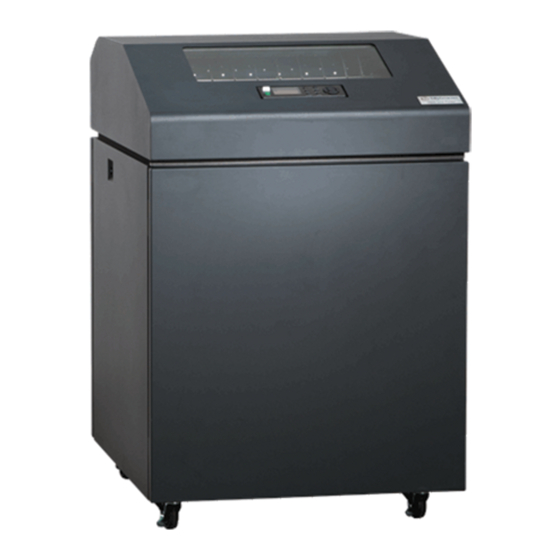
Five printer configurations are available: Cabinet (68XXQ) • The enclosed cabinet models provide for near silent operation, making these printers perfectly suitable for use in the quietest of office environments. • Provides the best paper handling for large print runs. All paper input and output is contained inside the cabinet and protected from bumping and contamination. -
Page 11: Taking Care Of Your Printer
Taking Care of your Printer Your printer will produce high quality print jobs if it is well taken care of. Periodic cleaning, handling the printer properly, and using the correct printer supplies such as ribbon and paper ensures optimum performance. Chapter 8 explains how to clean the printer, and printer supplies are listed in Appendix A. Conventions in this Manual Control panel keys and indicators are highlighted in UPPERCASE BOLD PRINT. -
Page 13: Setting Up The Printer
Setting Up The Printer Before You Begin Read this chapter carefully before installing and operating the printer. The printer is easy to install. However, for your safety and to protect valuable equipment, perform all the procedures in this chapter in the order presented. -
Page 14: Printer Dimensions
Table 2 Maximum Interface Connection Cable Length Interface Type Maximum Cable Length Centronics Parallel 5 meters (15 feet) IEEE 1284 Parallel 10 meters (32 feet) Serial RS-232 15 meters (50 feet) USB 2.0 Universal Serial Bus 5 meters (15 feet) Twisted Pair / Type 3 300 meters (985 feet) Ethernet 10/100Base-T... - Page 15 29.5 in (74.93 cm) 11.36 in (28.9 cm) 54.0 in (137.2 cm) 25.92 in (65.8 cm) 19.1 in 29.1 in (48.5 cm) (73.9 cm) Figure 2 Pedestal Model...
- Page 16 60.1 in (152.7 cm) 42.0 in (106.7 cm) 31.95 in (81.2 cm) 25.92 in 19.1 in (65.8 cm) (43.8 cm) 38.9 in (98.8 cm) Figure 3 Zero Tear Pedestal Mode...
-
Page 17: Printer Component Locations
Printer Component Locations Ribbon Ribbon Cartridge Tab (2) Ribbon Tension Knob Tractor (2) Blue Tractor Lock (2) Splined Shaft Paper Support (2) Hammerbank Cover and Ribbon Mask Tab Slot (2) Vertical Position Knob Platen Lever Platen Stop Ribbon Cartridge Interface Air Shroud Assembly Figure 4 Printer Component Locations... -
Page 19: Operating The Printer
Operating The Printer Powering on the Printer When you power on the printer, it executes a self-test. The default power-up state is offline. When the self-test completes and the software has initialized successfully, the status indicator light is off, indicating the printer is offline. -
Page 20: The Control Panel
The Control Panel Figure 5 shows the keys, displays, and indicators as they appear on the control panel. The following section provides the descriptions, and functions of the control panel keys. Key combinations are indicated with the plus (+) sign. For example, “Press ”... -
Page 21: Control Panel Keys
Control Panel Keys ONLINE Toggles the printer between online and offline modes. The key performs the following in Online, Offline, Fault, and Menu modes: • Online Mode – sets the printer to Offline Mode. • Offline Mode – sets the printer to Online Mode. •... - Page 22 NOTE: Use of this key will cause loss of data. Sets the top-of-form on the printer. This key is active only when the printer is offline and will not operate if the printer is in a fault condition. The paper moves down to the print position and aligns to the top-of-form. Refer to the User’s Setup Guide for complete instructions on how to set the top-of-form.
-
Page 23: Cancel A Print Job
UP + DOWN ( + ) Locks and unlocks the ENTER key. PREV or NEXT ( or ) Moves between the options on the current level of configuration menu. In the configuration menu, press to scroll backward or press to scroll forward through the menu selections on the same level. PREV + NEXT ( ... - Page 24 Zero Tear Pedestal Model Pedestal Model Wire Guide (2) Wire Guide Paper Slot Paper Slot Cabinet Model Metal Paper Guide (2000 lpm only) Paper Slot Figure 6 Paper Slot Location 1. Raise the printer cover. Raise the platen lever as far as it will go. (See Figure 4 on page 17 for the location of the lever.) NOTE: Do not open tractor doors or remove the existing paper.
- Page 25 New Paper Existing Paper Figure 7 Loading New Paper into the Printer 6. Pull the new paper above and behind the ribbon mask, but in front of the existing paper. See Figure 4 on page 17 for the ribbon mask location. If necessary, gently press the existing paper back. 7.
- Page 26 9. Turn the platen stop knob clockwise or counterclockwise to match the paper thickness. (The A-B-C scale corresponds approximately to 1-, 3-, and 6-part paper thickness). NOTE: If you are using the same thickness of paper, there is no need to readjust. 10.
- Page 27 Paper Tractor Tractor Splined Shaft Tractor Lock Paper Scale Figure 10 Positioning the Left Tractor to Avoid Damage CAUTION To avoid damage to the printer caused by printing on the platen, always position the left tractor unit directly to the left of the “1” mark on the paper scale. 21.
- Page 28 22. Unlock the right tractor. 23. Load the paper onto the sprockets and close the tractor door. If necessary, slide the right tractor to remove paper slack or to adjust for various paper widths. Then, lock the tractor. Zero Tear Pedestal Model Upper Paper Pedestal Model...
- Page 29 TOF Indicator Perforation Vertical Position Knob Figure 13 Aligning the Perforation with the TOF Indicator 26. Align the top of the first print line with TOF indicator on the tractor by rotating the vertical position knob. For best print quality, it is recommended that the top-of-form be set at least one print line or more below the perforation.
-
Page 30: Unload Paper
27. Turn the platen stop knob clockwise or counterclockwise to match the paper thickness. (The A-B-C scale corresponds approximately to 1-, 3-, and 6-part paper thickness. Adjust until you have the desired print quality). NOTE: The platen stop allows you to set an optimum and consistent thickness that is not affected when opening and closing the platen lever. -
Page 31: Integrated Print Management System
Tractor Door Platen Lever Figure 16 Completely Removing the Paper 8. To completely remove the paper from the printer: a. Raise the platen lever as far as it will go and open both tractor doors. CAUTION Be careful when pulling any paper backward through the paper path, especially when using a label stock. -
Page 32: Output Darkness
without losing data in the printer’s buffer. If a new ribbon is loaded, the system automatically detects the change, clears the condition when the platen is closed, and restarts the life at 100%. If a partially used ribbon is loaded, the system continues the life at the percentage indicated for the used ribbon. You may also resume printing for approximately two more minutes without changing the ribbon by pressing the ONLINE key twice. - Page 33 Blue Tractor Door (2) Platen Lever Figure 17 Preparing to Load the Ribbon 1. Open the printer cover. 2. Raise the platen lever as far as it will go. 3. Ensure the tractor doors are closed. 4. Remove the old ribbon cartridge and discard properly.
- Page 34 Ribbon Ribbon Cartridge Tab (2) Ribbon Tension Knob Tab Slot (2) Air Shroud Assembly Figure 18 Installing the Ribbon Cartridge 5. Remove the ribbon slack on the new ribbon cartridge by turning the ribbon tension knob clockwise. CAUTION Do not turn the ribbon tension knob counterclockwise. This could damage the ribbon cartridge.
- Page 35 Ribbon Cartridge Hammerbank Cover Ribbon Mask Ribbon Ribbon Tension Knob Ribbon Cartridge Figure 19 The Ribbon Cartridge Snapped in Place 7. Rock the cartridge downward, making sure that the ribbon goes between the guide and the mask (see Figure 19). You will feel it snap into place. CAUTION Make sure that the ribbon does not twist or fold over.
-
Page 37: Configuration Menus
Configuration Menus Configuration Overview To print data, the printer must respond correctly to signals and commands received from the host computer. Configuration is the process of matching the printer's operating characteristics to those of the host computer and to specific tasks, such as printing labels or printing on different sizes of paper. The characteristics which define the printer's response to signals and commands received from the host computer are called configuration parameters. -
Page 38: Navigating The Menus
Navigating the Menus To manipulate configurations review the following instructions about navigating through the menus. You must be offline to move within the menus. Press to toggle between ONLINE and OFFLINE. Press ENTER to enter Menu mode. Menus are accessed only in Menu mode. ONLINE Scroll up, down, left, or right through the icons to highlight the area of interest. -
Page 39: Top Level Menu Overview
Press to return to Offline mode. If changes were made, the user will be prompted to save or discard the configuration. ONLINE To experiment with navigating the menus, use the example on the next page as a tutorial. Top Level Menu Overview When entering Menu mode, the user will see top level menus represented as icons as shown below. -
Page 40: Changing Parameters Example
Changing Parameters Example OFFLINE *= Factory Default Operator Quick Menu Setup Font Forms Length Unidirectional Length (inches) (lines) Disable* Enable (0.1-25.5) (1-255) A configuration consists of several parameters. The default factory configuration has a starting set of parameters. In the configuration menu above, and in all the configuration menus in this chapter, the factory default values are indicated by an asterisk (*). - Page 41 Step Press Notes ENTER UNTIL ENTER The * indicates this choice is active. Press until the desired selection or value displays. ENTER The * indicates this choice is active. Press ENTER to go back into the menus or press ONLINE again to go ONLINE.
-
Page 42: Auto Save Configuration
Auto Save Configuration If the user makes a menu change and attempts to place the printer online without saving the changes to a configuration, the following prompt displays: The active option is highlighted. Use the Up and Down keys to scroll through the different options; the ↵... - Page 43 Example 1 This example shows how to save a configuration as a numbered configuration, then later print it. Step Press Notes Make sure the printer is on. ONLINE Shows the top level icons. ENTER UNTIL ENTER UNTIL ENTER Cycle through the choices. Configuration is in the process of ENTER being saved.
- Page 44 Step Press Notes The * indicates this choice is active. We recommend that you print the configuration. To print the configuration go to Step 10. To skip NOTE: this procedure and resume printer operation, go to Step 16. The Cancel Key will return back one level.
- Page 45 Step Press Notes ONLINE If you printed the configuration, store it in a safe place. The printer is ready for operation. Example 2 This example shows how to save a configuration as a named configuration. Step Press Notes Make sure the printer is on. ONLINE Shows the top level icons.
- Page 46 Step Press Notes UNTIL ENTER You will rename config. 2. The LCD flashes. ENTER Press the left or right key to choose the character that is highlighted. Press the up key to select the next character in the string. Press the down key to go back to the previous character and continue editing as necessary.
- Page 47 Step Press Notes UNTIL TEST now appears as one of the configuration choices. 19A. ENTER Your configuration is saved as 19B. TEST. Press ENTER to go back into the menus or press ONLINE again to go ONLINE. ONLINE ONLINE Now you have the saved configuration for later use if needed.
-
Page 48: 6800 Crp Main Menu
6800 CRP Main Menu OFFLINE If Ethernet is installed. If Parallel is installed. If SD is installed. Operator TCP/IP Quick Setup Config Menu Test Menu Menu Menu Help Menu page 49 page 62 page 87 page 51 page 84 Host Interface Font Printer Ethernet Address... -
Page 49: Quick Setup
Quick Setup Quick Setup * = Factory Default (from page 48) If Ethernet is installed. If Parallel is installed. Host Emulation Ribbon Configuration Clear Interface Active Host Ribbon End Point Save Config. Buffers Ser/Par Emul Auto Switching* Darker +6 Cfg 1* All Configs Tally ANSI* Centronics... - Page 50 Emulation • Ser/Par Emul. This parameter allows you to define which set of printer control commands will be emulated for data received on the Serial and Parallel ports. Tally ANSI is the default selection. This menu also enables you to define the form length, characters per inch (cpi) and lines per inch (lpi). When a new emulation setting is entered through the Printer Control Panel, emulation dependent parameters in the Current configuration changes to match the default settings for the elected emulation.
-
Page 51: Operator Menu
• LPI. This parameter allows you to set the lines per inch (LPI). The possible selections are 1.5, 2, 3, 4, 5, 6, 8, 9, 10, and 12. The default setting is 6 LPI. Ribbon Ribbon End Point. This parameter adjusts the point at which the system will declare the ribbon as being expended. -
Page 52: Font Submenu
Font Submenu This submenu contains parameters that control how print looks on a page and the display language. The Level 2 headings are as follows: Font * = Factory Default (from page 51) OCRA Ser/Par Ser/Par Ser/Par Matrix Density Style Lang Char Set CDF*... - Page 53 Ser/Par Lang This option allows you to select the language used by emulations attached to the Parallel, Serial, and LAN ports. The language selection defines the character substitutions in Hex locations 23, 24, 40, 5B, 5C, 5D, 5E, 60, 7B, 7C, 7D, and 7E. The default is US. Refer to the 6800 Emulations Manual for details on character substitutions.
- Page 54 Refer to the 6800 Emulations Manual for details on character sets. The possible selections are: Latin1 8859-1 Latin2 8859-2 Latin9 8859-15 Cyrillic 8859-5 Greek 8859-7 Turkish 8859-9 Code Page 437 Code Page 850 Code Page 851 Code Page 852 Code Page 855 Code Page 857 Code Page 863 Code Page 866...
- Page 55 Ser/Par Style This option allows you to select the font style for use by emulations attached to the Parallel, Serial, and LAN port. For emulations that support downloaded fonts, you can use this parameter to select the download font. The default is DP. Style selections include: Draft (High-speed)
- Page 56 • Medium. Prints a normal bold text character. Although selecting this weight reduces print speed, it provides the best boldness appearance. • Dark. Prints a thick bold character. This weight is best for 10 and 12 CPI characters and provides an increase in print speed over the Medium weight.
-
Page 57: Forms Submenu
Forms Submenu This submenu is used for setting form specifics. The Level 2 headings are as follows: * = Factory Default 2000 lpm printer only. FORMS 1000 lpm printer only. (from page 51) Default is 15 minutes for cabinet models. Length Length Bottom... - Page 58 Length (lines) To define the length of your form in lines, select a form length from 1 to 255. The default option is 66. Length (inches) To define the length of your form in inches, select a form length from 00.1 to 25.5 inches.
- Page 59 Quick Access This option provides a way for a pedestal printer to position printed forms for quick tear-off access. When Quick Access is enabled, the paper is moved to the tear position by holding down the VIEW key for one second for Eject.
- Page 60 NOTE: Printing will only stop on the first occurrence of a ribbon low condition. Once the user clears the warning message, subsequent warnings will display the warning message, but printing will continue. RBN End Action This menu allows the user to override the normal ribbon low warning and ribbon out conditions. •...
-
Page 61: Vertical Format Units (Vfu) Submenu
Vertical Format Units (VFU) Submenu This submenu is used for setting VFU specifics. The Level 2 headings are as follows: (from page 51) * = Factory Default Skip When Enable Channel Disable* Before* Enable After 1-12 Unused VFU Enable A Vertical Format Unit is a means for loading sets of vertical tabs. These vertical tabs define various parameters of a form. -
Page 62: Config Menu
Config Menu * = Factory Default Config Menu If Parallel Installed. (from page 48) If SF card is installed. Host Printer Codes Graphics Configurations USB I/O Serial I/O Interface (see below) (see page 65) (see page 69) (see page 73) (see page 75) (see page 76) (see page 77) - Page 63 Ser/Par Emul This parameter allows you to define which set of printer control commands will be emulated for data received on the Serial and Parallel ports. The emulation settings are automatically saved in the Powerup Configuration. Tally ANSI is the default selection. When a new emulation setting is entered through the Printer Control Panel, emulation dependent parameters in the Current and Powerup configurations are changed to match the default settings for the elected emulation.
- Page 64 Dump Mode Dump Mode is used to troubleshoot problems that may arise when processing data. It places the printer into a Hex Dump Mode. You can select three styles of printouts for use as debugging tools. The standard selections are: •...
-
Page 65: Codes Submenu
Codes Submenu * = Factory Default If P5000 emulation is selected. CODES If Genicom ANSI emulation is selected. (from page 62) Wrap Form Feed Auto LF Auto CR Line Wrap Print on CR Line Feed At TOF OFF* OFF* Enable* OFF* OFF* OFF*... - Page 66 Line Wrap If the printer gets to the right margin without receiving a paper movement command, the Line Wrap Parameter dictates how the rest of the data will be treated. If Line Wrap is OFF, the excess characters are lost. If Line Wrap is ON, printer response is determined by the Wrap Line Feed parameter (see below). If Line Wrap is ON and Wrap LF is OFF, the printer performs a Carriage Return only and overprinting can result.
- Page 67 Upper Only This parameter allows you to set up your printer to print in uppercase characters only from the active Character Set. When this parameter is enabled, the lower-case characters in Hex positions 61 through 7A are overwritten by the uppercase characters in positions 41 through 5A. The default is Disable. Code 7F This parameter allows you to dictate how the printer will react when it receives a Hexadecimal code 7F.
- Page 68 TOF Control (Available when Genicom ANSI emulation is selected) When a new form is defined, the top-of-form position is left unchanged if this parameter is set to Enable (the default). When a new form is defined, and this parameter is set to Disable, the top-of-form position is reset to the top margin of that form.
-
Page 69: Graphics Submenu
Graphics Submenu This submenu allows you to configure certain aspects of the Graphic Processing Options on your printer. The Level 2 headings are as follows: * = Factory Default Graphics (from page 62) If MTPL emulation is selected If Genicom ANSI emulation is selected Code V Smooth Size PY Then... - Page 70 Code V Cmd Char This parameter allows you to change the CVCC. The Default for this parameter is the ASCII caret ( ^ , Decimal 94, HEX 5E) character. Smooth Size This parameter controls the size at which block characters are smoothed. The default is 3, which means that size 3 block characters will be smoothed, but size 2 block characters will not.
- Page 71 Version This parameter controls the version of Code V the printer emulates. Version 2 is the default selection. Descender This parameter controls insertion of the character descender gap between print lines. • Fixed (default). The descender gap is always inserted after the line whenever Descender Mode is ON regardless of whether descenders are present or not.
- Page 72 Swedish/Finnish Norwegian/Dan Japanese German French Italian Spanish PGL Language This parameter allows you to select the language character set that will be used for text output in Printronix Graphics Mode. The default is ASCII. The available selections are: ASCII German Swedish Danish Norwegian...
-
Page 73: Configurations Submenu
PGL Terminator Determines whether or not a CR-LF terminator for PGL commands will cause a line feed to occur. • CR. Allows line feeds which follow the carriage return to be executed. Example: ~EXECUTE;TEST<cr><lf> <cr><lf> ~NORMAL<cr><lf> The above example would execute three line feeds following the job TEST. •... - Page 74 Save Config. This option allows you to save up to eight configurations to meet different print job requirements. This eliminates the need to change the parameter settings for each new job. The configurations are stored in memory and will not be lost if you turn off the printer. The factory default configuration cannot be changed.
-
Page 75: Host Interface Submenu
Host Interface Submenu * = Factory Default Host Interface If Ethernet is installed. (from page 62) If Parallel is installed. Parallel Serial Ethernet Active Host Hotport Hotport Hotport Hotport Auto Switching* Port Type Trickle Time Timeout Timeout Centronics Centronics* 1/4 sec* 30 sec.* 30 sec* Serial... -
Page 76: Usb I/O Submenu
Trickle Time When the printer is printing data from a host and a second job is received by the printer from a different host, Trickle Time prevents the second host from timing out while it is waiting for its data to be printed. To support this feature, the port has to be able to accept data from the host and store it for future use. -
Page 77: Serial I/O Submenu
Serial I/O Submenu Serial I/O * = Factory Default (from page 62) Baud Data Bits Stop Bits Parity 8th Bit Protocol 8 Bits* 1 Bits* None* Data* Ready/Busy* 1200 7 Bits 2 Bits Unused Xon/Xoff 2400 Even Enq/Ack 4800 Etx/Ack 9600* Etx/Ack/Nak 19200... - Page 78 8th Bit If 8 bits per byte is selected under Data Bits above, use this parameter to determine how the 8th bit is to be used. If this bit is to be ignored, set the parameter to Unused. If the bit is to be used, set the parameter to Data.
- Page 79 Table 5 Status Enquiry Response Bit Pattern Meaning/Value Parity if 7 bit data and parity enabled (MSB) Always a 0 Always a 1 Always a 1 0 if Parity Error, Data Overrun, or Buffer Overflow 1 if Offline 1 if Busy (fault or buffer full) 1 if Paper System Error or Platen Open (LSB) DTR Function This parameter allows the user to change the operation of the Data Terminal Ready (DTR) line on the...
-
Page 80: Parallel I/O Submenu
Buffer Size in K This option configures the amount of memory allocated for the serial port buffer. You may specify between 1 and 16 Kbytes, in 1-Kbyte increments. The default is 16K. Unsolicit Rpt This option enables or disables Printer Device Status Reports to be sent to the host when a reportable status or error condition has occurred. -
Page 81: Intellifilter Submenu
Enable Delete Intellifilter is a programmable feature, standard on TallyGenicom line printers. Without having to touch a well-working host system, Intellifilter permits users to free their systems from hard coded dependence on a specific printer that is no longer maintainable, or able to meet the demands of the application. -
Page 82: Main File Mgmt Submenu
Serial, Parallel, LAN • Disable (default). The Intellifilter will be Disabled on the respective port. • Enable. The Intellifilter will be Enabled on the respective port. File Management • Download. This selection will place the printer in the IntelliFilter download mode. •... -
Page 83: Sd File Mgmt Submenu
Optimize&Reboot Reclaims flash space from deleted flash files. After pressing ENTER, wait for the printer to reboot. NOTE: When the Optimize&Reboot option is executed, the message, “Optimizing Flash Files” does not display before printer rebooting takes place. IMPORTANT Do not turn the printer off until it has completely rebooted and is either back online or offline. -
Page 84: Cst/Paa Submenu
Erase QCMC Erases the QCMC image stored on the SD card (see Appendix D, Quick Change Memory Card (QCMC). CST/PAA Submenu Refer to the PrintNet Enterprise Suite User’s Manual. PTX_SETUP Option Submenu PTX_SETUP Option (from page 62) * = Factory Default Setup Parse Setup SFCC Enable*... -
Page 85: Ethernet Address
Ethernet Address Ethernet * = Factory Default Address (from page 84) Gateway IP Address Subnet Mask Address Address Assignment xxx.xxx.xxx.xxx DHCP xxx.xxx.xxx.xxx hhhhhhhhhhhh xxx.xxx.xxx.xxx Enable* Disable BootP Disable* Enable IP Address A numeric address such as 123.45.61.23 which identifies a printer or server in a LAN or WAN. Subnet Mask A binary value used to divide IP networks into smaller networks or subnets. -
Page 86: Ethernet Params
Ethernet Params Ethernet * = Factory Default Params (from page 84) ASCII Keep Alive Ethernet Offline Job Control Data Port Timer Speed Process 9100* Disable* Auto Select* Standard* 3 Minutes* 1025-65535 Enable 10 Half Duplex Enhanced 0-10 Minutes 10 Full Duplex Fast Standard 100 Half Duplex 100 Full Duplex... -
Page 87: Test Menu
• Enhanced. The NIC waits for the printer to finish receiving the current job before sending another job. The status line shows “done” when the job is fully printed. • Fast Standard. The EOJ (End of Job) packet is acknowledged immediately. Use this selection if the job is timed out due to a delay in the acknowledgement of the EOJ packet because of the amount of data being printed. -
Page 88: Pattern Submenu
Pattern Submenu The Pattern Submenu has a series of printer self-tests which have predefined patterns used to test the basic printer functions. Printer Tests These tests are used to check the print quality and operation of the printer. NOTE: Your authorized service representative will typically run the tests. They are described in more detail in the Maintenance Manual. -
Page 89: Fault Override Submenu
“autodbg1.dbg” or “autodbg2.dbg” in the printer file system. This file can be uploaded to the host using the PrintNet Enterprise Suite application. Upon receipt of this file, it should be sent to TallyGenicom Customer Support for review and evaluation. Fault Override Submenu... -
Page 90: Diag Submenu
Paper Motion This parameter controls paper motion fault reporting status. This setting is saved in NVRAM so that it does not need to be set up on powerup each time. Shuttle Off The amount of time the shuttle continues moving after no data is received. If your host is slow, setting the number to a higher value will prevent the printer from spending time shuttling up and down between data bursts. -
Page 91: Interfaces
Interfaces Overview This chapter describes the host interfaces provided with the printer. The printer interface is the point where the data line from the host computer plugs into the printer. The interface processes all communications signals and data to and from the host computer. Plus, with the Auto Switching feature, you can configure the printer to accept several interfaces at the same time (see Auto Switching on page 75). - Page 92 Optional Parallel I/O Connection Serial Port (RS-232) Debug Port USB 2.0 Ethernet 10/100 BaseT Figure 21 Cabinet Model Interface Connectors Optional Parallel I/O Connection Serial Port (RS-232) USB 2.0 Ethernet Debug Port 10/100 BaseT Figure 22 Pedestal Model Interface Connectors...
-
Page 93: Rs-232 Serial Interface
RS-232 Serial Interface NOTE: The RS-232 serial interface circuit characteristics are compatible with the Electronic Industry Association Specifications EIA-232-E and EIA-422-B. The RS-232 serial interface enables the printer to operate with bit serial devices that are compatible with an RS-232 controller. The input serial data transfer rate (in baud) is selectable from the printer's control panel. -
Page 94: Usb
Menus The Universal Serial Bus (USB) port is part of Auto Switching and is active when the Host Interface menu is set to Auto Switching. It can also be selected as the only Host Interface under the Host Interface menu by selecting USB. -
Page 95: Centronics Parallel Interface Signals
Centronics Parallel Interface Signals Data Lines 1 through 8. Provides eight standard or inverted levels from the host that specify character data, plot data, or a control code. Data Line 8 allows access to the extended ASCII character set. You may enable or disable this line via the Data Bit 8 parameter on the Centronics submenu. - Page 96 Table 9 1284 Signals Type of Mode Source of Data Compatible Nibble Byte Host nStrobe HostClk Host/Clk Host/Printer Data 1 (LSB) Host/Printer Data 2 Host/Printer Data 3 Host/Printer Data 4 Host/Printer Data 5 Host/Printer Data 6 Host/Printer Data 7 Host/Printer Data 8 (MSB) Printer nAck...
-
Page 97: Ethernet
Table 9 1284 Signals Type of Mode Source of Data Compatible Nibble Byte Host nInit Printer NFault nDataAvail aDataAvail Not Defined Not Defined Not Defined Host nSelectIn 1284 Active 1284 Active NOTE: The length of the data cable from the host computer to the printer should not exceed 32 feet (10 meters). -
Page 99: Reprogramming The Security Key
Reprogramming the Security Reprogramming the Security Key The security key on the PSA3 controller board can be reprogrammed with a Software Program Exchange (SPX) module. The SPX is an intelligent module that plugs into the debug port on the back of the 6800. The SPX is used only once;... - Page 100 4. Power on the printer. The printer will begin its boot-up sequence. 5. When the printer detects a valid SPX, the control panel displays: “NEW SPX DETECTED PRESS ENTER” NOTE: If an error message displays, find the message in the Message List in Chapter 8 and follow the troubleshooting instructions.
-
Page 101: Downloading Firmware
Downloading Firmware The controller board contains 256 MB of FLASH memory. The printer firmware which includes the printer control languages (emulations), engine control, and printer operating system software are loaded into FLASH memory at the factory, but there are occasions when you may need to load the software: •... -
Page 102: Firmware File Types (.Prg) And (.Exe)
Table 10 Firmware Download Methods User FLASH Firmware Download Method File Type(s) Files WebPanel (Ethernet only) FILENAME.prg Preserved Requirements: network option installed, a browser, and the IP address. Automatic download (any host IO) FILENAME.exe Preserved Using the FILENAME.exe, firmware can be downloaded from a Windows Command Prompt without having to manually put the printer into download mode. - Page 103 5. Click “Printer Configuration”, “Configuration Management”, or “File Management” as shown in Figure Figure 24 Selecting Printer, Configuration, and File Management Options 6. Click the “System” link in the top header section (see Figure 25). Figure 25 System Configuration Screen 7.
- Page 104 Figure 26 Upgrading Firmware 9. A Warning message appears (Figure 27). Click “OK”. Figure 27 Firmware Upgrade Warning 10. Click “Yes” to confirm reboot (Figure 28). Figure 28 Rebooting after Downloading Firmware Upgrade 11. Wait until the printer finishes firmware upgrade and restarts (Figure 29).
-
Page 105: Automatic Download (.Exe)
4. For USB connections, the Windows Driver must be installed. Install the Windows Driver on the Starter Kit CD before continuing. Alternatively, drivers can be found at http://www.tallygenicom.com/products/drivers.aspx. During installation, make sure to share the printer when prompted and record the “Share name”... - Page 106 5. For USB connections, the printer must have a “Share name” established. The “Share name” will be required when executing the FILENAME.exe command. This should be accomplished during installation, but can be verified at any time. Select the driver, right-click the mouse button and select “Printer Properties”.
-
Page 107: Manual Two-Key Download Sequence
Connection Command Type Parallel FILENAME –a -pb <Enter> Serial mode COM1:9600,N,8,1 <Enter> mode LPT1=COM1 <Enter> FILENAME –a -pb <Enter> FILENAME –a –pbSharedName <Enter> where SharedName of the printer is the ‘Share name’ entered during installation. Ethernet FILENAME -n xxx.xxx.xxx.xxx <Enter> where xxx.xxx.xxx.xxx represents the IP address IMPORTANT DO NOT interrupt the download process once it has started. -
Page 108: Sending Firmware In Download Mode
This can be completed with firmware in the form FILENAME.exe or FILENAME.prg. When the printer is in download mode, only USB or parallel can be used to download the firmware. 1. Set the printer power switch to O (Off). 2. Connect the Ethernet cable to the printer interface. 3. -
Page 109: Sending Firmware Via Usb
5. When download is complete, exit the FTP program by typing: quit <Enter> IMPORTANT DO NOT interrupt the download process once it has started. Interrupting a download will leave the flash memory on the controller PCBA and NIC incompletely loaded, and the printer may not boot up. When the new software has successfully loaded into flash memory and the printer has reset itself, the process is complete. - Page 110 b. Select “Control Panel”. c. Click “Add Hardware Wizard”. For Windows 7: a. Click the “Start” menu. b. Select “Control Panel”. c. Click “Hardware and Sound”. d. Under “Device and Printers”, click “Device Manager”. e. Select your PC and start the “Add legacy hardware” process from the “Action” menu as shown below.
- Page 111 5. When prompted for hardware installed options, select “Advanced” which that allows you to select the hardware from a list. Then click the “Next”. 6. Select “Network adaptor”, then click the “Next”. 7. Select “Microsoft Loopback Adapter”, then click the “Next”.
- Page 112 8. Click the “Next” button. Installation is complete. Verify the proper installation in the following steps. 9. To verify installation, go back to the Control Panel and select “System” for WinXP. Under the “Hardware” tab, select “Device Manager”. For Windows 7, select “Device Manager” directly from Control Panel.
-
Page 113: Sending Firmware Via Parallel
10. Select the “Network Adaptors” and expand the selection if necessary. “Microsoft Loopback Adaptor” is listed. Leave all settings as default. You are now finished and may proceed as outlined in Sending Firmware via USB on page 109. Sending Firmware via Parallel This method of download can be completed with firmware in the form FILENAME.exe or FILENAME.prg. -
Page 114: Downloading Files To The Main File System
IMPORTANT Some systems can only use the 9600 baud rate. The baud rate information entered in the above commands must match the Baud Rate setting saved in the Power-Up Config. IMPORTANT DO NOT interrupt the download process once it has started. Interrupting a download will leave the flash memory on the controller PCBA and NIC incompletely loaded, and the printer may not boot up. -
Page 115: Webpanel File Download
WebPanel File Download 1. Make sure the printer online and that the Ethernet cable is connected. 2. Obtain the IP address from the front panel (under TCP/IP Menu icon in the menus). 3. Enter the IP address of the printer in your browser (e.g., http://10.224.5.34). 4. -
Page 116: Ptx_Setup Download
PTX_SETUP Download PTX_SETUP can be used to load files into the Main File System. See The PTX_SETUP Commands on page 165. Example loading a font named ARIAL.TTF: !PTX_SETUP FILE_IO-CAPTURE;“ARIAL.TTF” PTX_END Arial TrueType font binary data NOTE: Do not add any LF/FF at the end of the binary data !PTX_SETUP FILE_IO-CAPTURE;””... -
Page 117: Downloading Files To The Sd Card
Demo Facility It may be desired to exercise the function of a TallyGenicom printer in an environment where there is no host computer system available. This might include the need to execute a particular type of “demo” test file from the menu system. -
Page 118: Configuring The Printer To Run A Demo File
Configuring the Printer to run a Demo File This facility makes no attempts to identify which emulation a particular demo file is designed for. The user must configure the printer for the appropriate emulation before invoking the demo. The demo will inherit all menu configuration parameters when executed. -
Page 119: Troubleshooting
Troubleshooting Cleaning Requirements Clean the printer every six months or after every 1000 hours of operation, whichever occurs first. If the printer is located in a dusty area or is used for heavy duty printing, clean it more often. WARNING Disconnect the power source before cleaning the printer. - Page 120 Ribbon Ribbon Cartridge Tab (2) Ribbon Tension Knob Tractor (2) Blue Tractor Lock (2) Splined Shaft Paper Support (2) Hammerbank Cover and Ribbon Mask Tab Slot (2) Vertical Position Knob Platen Lever Platen Stop Ribbon Cartridge Interface Air Shroud Assembly Figure 34 Interior Printer Components...
-
Page 121: Diagnosing Problems
To clean the interior of the printer perform the following steps. 1. Power off the printer and unplug the printer power cord. 2. Open the printer cover. 3. Fully raise the platen lever. 4. Unload the paper. 5. Remove the ribbon cartridge. 6. -
Page 122: Printing A Hex Dump
Printing a Hex Dump A hex code printout (or hex dump) is a translation of all host interface data to its hexadecimal equivalent, listing all ASCII character data received from the host computer with their corresponding two-digit hexadecimal codes. Hex dumps are used to troubleshoot printer data reception problems. Printable characters print as the assigned symbol;... - Page 123 The CD contains a utility called hexcode.exe. This utility can be run from a DOS window to convert an input file into a hexadecimal equivalent. The output from this utility can then be used to compare what is received when printing a hex dump. Usage: hexcode <input file>...
-
Page 124: Most Frequent Problems And Solutions
PrintNet Enterprise Suite and sent to TallyGenicom Customer Support Center for analysis (see Appendix D, page 159). This diagnostic option must be enabled for the printer to capture the information. If you choose to perform this diagnostic perform the following procedure: 1. -
Page 125: Fault Messages
5. If present, use PrintNet Enterprise Suite to upload these files to your host computer. 6. Contact TallyGenicom Customer Support Center and send them the files along with the printer’s configuration printout. Refer to the PrintNet Enterprise Suite User’s Manual on how to accomplish these tasks. - Page 126 Table 13 LCD Message Troubleshooting Table Can User Displayed Message Explanation Solution Correct? B20 STATUS:00% Status message informing No action is required. DOWNLOAD MODE the operator that software is being downloaded. Percentage figure indicates approximate amount loaded into the printer. B21 STATUS: PRINTER Status message informing No action is required.
- Page 127 Table 13 LCD Message Troubleshooting Table Can User Displayed Message Explanation Solution Correct? BAD NVM CALL 1 Printer firmware code Cycle power. Run the print BAD NVM CALL 2 error with the Novram job again. If the message BAD NVM CALL 3 module that stores appears, load the latest BAD NVM CALL 4...
- Page 128 Table 13 LCD Message Troubleshooting Table Can User Displayed Message Explanation Solution Correct? COIL TEMP FAIL The coil temperature Allow printer to cool was never set or the completely, then set coil attempt to set it did not temperature. If message result in correct continues to display, numbers.
- Page 129 Table 13 LCD Message Troubleshooting Table Can User Displayed Message Explanation Solution Correct? CARTRIDGE/ SHUTTLE This message displays Install Standard Life Cartridge. MISMATCH when an Extended Life Use Correct Cart Cartridge is mounted on a 500 lpm printer. CARTRIDGE/ The incorrect cartridge Install the correct ribbon TIPSIZE MISMATCH type is being used for...
- Page 130 Table 13 LCD Message Troubleshooting Table Can User Displayed Message Explanation Solution Correct? Cycle Power. Run the E00 EXE @ ADDR0 An illegal or unsupported E01A TYPE 0x40 instruction was print job again. If the E01B TYPE 0x60 attempted in the message appears, load E02 MACHINE CHK application program.
- Page 131 Table 13 LCD Message Troubleshooting Table Can User Displayed Message Explanation Solution Correct? ERROR OCCURRED An interim message that Wait. When the asterisk (*) FLUSHING QUEUES* displays while the printer stops rotating, a different discards host data it fault message will appear: cannot use because a troubleshoot the final fault condition exists.
- Page 132 Table 13 LCD Message Troubleshooting Table Can User Displayed Message Explanation Solution Correct? ERROR: WRONG PRINTER The SPX inserted in the Contact your authorized TYPE debug port is not service representative. intended for this model printer or this OEM. ETHERNET DETECTED Status message indicating No action is required.
- Page 133 Table 13 LCD Message Troubleshooting Table Can User Displayed Message Explanation Solution Correct? FLASH: WAS NOT Printer encountered an Contact your authorized CLEARED error while trying to service representative. program Flash memory. Contact your authorized FLASH: WRITE ERROR # 2 Printer encountered an error while trying to service representative.
- Page 134 Table 13 LCD Message Troubleshooting Table Can User Displayed Message Explanation Solution Correct? HAMMERBANK NOT Hammer Bank Not Contact your authorized INSTALLED* Installed. Self-test service representative. routines do not detect hammer coils at printer start-up. HMR BANK FAN FLT Sensor cannot detect Check that fan cable is current in fan circuit.
- Page 135 Table 13 LCD Message Troubleshooting Table Can User Displayed Message Explanation Solution Correct? INTERRUPT UNUSED The controller board Cycle power. If this message VECTOR 00 receives an interrupt it occurred once and never does not understand. The again, you can ignore it. If problem can be created the message reappears or by electrical noise, by a...
- Page 136 Table 13 LCD Message Troubleshooting Table Can User Displayed Message Explanation Solution Correct? PAP FD DRVR CIR* Paper Feed Driver Contact your authorized See Manual Circuit. The paper service representative. feed driver circuit on the controller board is drawing too much current.
- Page 137 Table 13 LCD Message Troubleshooting Table Can User Displayed Message Explanation Solution Correct? POWER SUPPLY HOT Power supply sensors Check printer environment. If report high temperatures. hot or dusty, relocate printer. Contact your authorized service representative if this occurs frequently. PRINTER HOT This message indicates Check printer environment.
- Page 138 Table 13 LCD Message Troubleshooting Table Can User Displayed Message Explanation Solution Correct? RIBBON UNDER 2% Status message Install a new ribbon. Change RBN Soon indicating the Integrated Print Management System is enabled and ribbon ink level is 2%. SD CARD ERROR The printer has been Power down, reseat card, and Remove SD Card...
- Page 139 Table 13 LCD Message Troubleshooting Table Can User Displayed Message Explanation Solution Correct? SD WRITE FAIL A write operation to Ensure that the write protect WRITE PROTECTED the SD has failed tab on the SD card is not Check SD Card because the SD card active.
- Page 140 Contact your authorized Corrupted. Firmware error service representative. on controller board. TCP PORT BUSY Error message reported Refer to the TallyGenicom by the Printer Manager 6800 Maintenance Manual. when ethernet interface option is installed. The network address given in the printer properties was reached, but the printer port is busy.
- Page 141 Table 13 LCD Message Troubleshooting Table Can User Displayed Message Explanation Solution Correct? WELD NOT DETECT The cartridge weld Contact your authorized service See User Manual was not detected. representative. WELD SNSR ERROR The cartridge sensor Make sure your cartridge See User Manual could not be calibrated.
-
Page 143: Printer Specifications
Printer Specifications Ribbon Cartridge Specifications North America, Asia Pacific Europe, Latin America (excludes India and Middle East, (excludes Brazil), China and Brazil & Africa Canada India) Extended Life, 1 Pack -101 -102 -103 -104 Extended Life, 4 Pack -401 -402 -403 -104 Standard Life, 1 Pack... -
Page 144: Printer Weight And Dimensions
Printer Weight and Dimensions Dimensions Weight Cabinet Type Height Width Depth Unpacked Packaged (inches) (inches) (inches) (pounds) (pounds) Cabinet 42.5 Open Pedestal 24.5 Zero Tear Pedestal 42.04 25.75 19.48 Environmental Characteristics Temperature: Operating: 50° to 104° F (10° to 40° C) up to 5000 feet (1524 meters) 50°... -
Page 145: Electrical Characteristics
Electrical Characteristics Printer Voltage (+/- Freq (+/- Configuration Amps Watts BTU/Hr Type 10%) 10%) Cabinet 6805Q AC 100-240V 50/60 Hz 320W 1093 Cabinet 6810Q AC 100-240V 50/60 Hz 320W 1093 Cabinet 6815Q AC 100-240V 50/60 Hz 475W 1622 Cabinet 6820Q AC 100-240V 50/60 Hz 475W... -
Page 147: Ascii Character Set
ASCII Character Set OCTAL DECIMAL ASCII CHARACTER BITS COLUMN B4 B3 B2 B1 0 0 0 0 0 0 0 1 (XON) " 0 0 1 0 0 0 1 1 (XOFF) 0 1 0 0 0 1 0 1 &... -
Page 149: Zero Tear Pedestal Printer
Zero Tear Pedestal Printer Overview The P8000 Zero Tear Pedestal (ZTP) printer can print a form and present it for tear off without losing a form between print jobs. The printer automatically presents the current print line to the tear bar when it finishes printing and no data are being sent to the printer. - Page 150 NOTE: This operation is typically done during initial setup. Before beginning the procedure, ensure that the paper guides are not damaged. 1. Remove the left paper guide knob and the left, front paper guide leaf. (See Figure 36.) 2. Remove the right paper guide knob and the right, front paper guide leaf. 3.
-
Page 151: Load Paper
Load Paper Outer Paper Guide Leaf (2) Center Paper Guide Leaf Tractor Door Front Paper Guide Leaf (3) Paper Paper Edge Paper Paper Out Sensor Label Paper Supply Box Figure 38 Loading Paper onto the Printer 1. Align the paper supply box with the label on the left side of the floor. (See Figure 38 on page 151.) 2. - Page 152 Paper Tractor (2) Tractor Lock (2) Figure 39 Adjusting the Horizontal Paper Tension 5. Adjust the paper web tightness by sliding the right tractor to remove slack or to adjust for various paper widths. (See Figure 39.) 6. Lock the tractors in position by pressing down on the tractor locks. Paper Tear Bar Figure 40 Paper Exiting the Top of the Printer...
-
Page 153: Position The Paper Out Sensor
Position the Paper Out Sensor At least 2 inches Sensor Knob Paper Out Sensor Paper Figure 41 The Paper Out Sensor The paper out sensor indicates when the printer runs out of paper. (The sensor does not work with black backed forms.) Unlike the standard pedestal printer, the ZTP printer requires you to load the paper through the paper out sensor slot (Figure 38 and Figure 41). -
Page 154: Set The Tear Bar Distance
Set the Tear Bar Distance To set the tear bar distance, do the following steps: 1. Make sure the printer is offline. 2. Press ENTER key to enter Menu mode. 3. Press the right arrow until the Config Menu icon is highlighted. 4. -
Page 155: Set The Top Of Form
Set the Top of Form Paper Tear Bar Form Advance Knob Figure 43 Setting The Tear Off Position The ZT printer uses the tear bar as the reference point for setting the tear off position. To set the position of the forms perforation to the tear bar, use the TOF button as follows: 1. -
Page 156: Ztp Settings Menu
ZTP SETTINGS Menu The ZTP SETTINGS menu includes the ability to enable and disable features unique to the Zero Tear printer (ZTP), set the tear bar distance, set the auto present data time, and set the auto present wait time. This section defines these options. -
Page 157: Performance Considerations
Performance Considerations Forms Type The paper feed tractors on the ZTP printer push the paper up through the print station instead of pulling it through, as in the standard pedestal printer. This limits the variety of forms the ZTP printer can use. If the forms do not fall within the range specified in Table 15, dot compression, line separation, and jamming may occur. -
Page 158: How To Set The Ztp Printer To Help Mitigate Paper Jams
Clearing Paper Jams or Removing Paper 1. Raise the platen lever to open the platen. 2. Open the left and right tractor doors. 3. Pull the paper upward through the top of the printer. NOTE: DO NOT pull the paper downwards from the bottom. This could cause the paper guides to bend. 4. -
Page 159: Quick Change Memory Card (Qcmc)
Quick Change Memory Card (QCMC) Overview The QCMC provides the ability to duplicate an entire printer’s firmware, saved configurations, and custom files quickly through the printer’s control panel with a user friendly interface. No external host or files are needed to transfer this information to the QCMC. A “snapshot image” is saved of the printer’s firmware, configuration settings, and custom files. -
Page 160: Installing The Qcmc
Installing the QCMC CAUTION You must power off the printer before you install or remove the QCMC, or you may damage the QCMC and the printer. If you remove the QCMC after powering on the printer with the QCMC installed, the fault message “SD REMOVED Reboot Printer” will display. -
Page 161: Saving The Printer's Configuration To The Qcmc
Saving the Printer’s Configuration to the QCMC NOTE: The MAC address residing on the QCMC will be used in place of the MAC assigned to the printer’s own network card whenever the QCMC is installed. If you do not want to identify the printer with this MAC address, make sure the QCMC is removed from the printer before attaching the printer to the network. -
Page 162: Copying The Qcmc "Snapshot" Image To A Second Printer
Save Complete Printer Will Now Reboot... If there is not enough space on the SD to save the entire flash image, you will be prompted with the following message. NOT ENOUGH SPACE ON SD Delete SD File This is a fatal error and requires user intervention. Cycle power on the printer, when prompted to save the QCMC select <CANCEL>... - Page 163 INVALID SD Power Off Printer Remove Cartridge This means that the QCMC is not compatible with the printer’s software. A software upgrade is required, or a different configured QCMC will be needed. A QCMC validation check will be performed to ensure the data stored on the SD is not corrupted. If the test fails the following fault message will display.
-
Page 165: Ptx_Setup Commands
PTX_SETUP Commands Overview The PTX_SETUP commands are a superset of commands which allow the printer to perform several tasks by parsing commands either stored in flash or sent to the printer by the host. Commands range from printer configuration operations to file system operations. This appendix describes the PTX_SETUP commands. - Page 166 Table 16 lists all the command, sub-command, and parameter combinations and gives a brief description of the command. Table 16 PTX_SETUP Commands (Non-Platform Specific) Command Sub-Command Parameter Description CONFIG LOAD Cfg can be 0-8. The PTX_SETUP will load configuration Cfg. If configuration Cfg was not previously saved, the operator panel will display an error message and the current...
- Page 167 Table 16 PTX_SETUP Commands (Non-Platform Specific) Command Sub-Command Parameter Description CONFIG OVERLAY This command overlays the configuration data that follows on existing configuration Cfg. Cfg must be 1-8 (or END). If Cfg does not exist then command is treated the same as DOWNLOAD. RESET Reboots the printer.
- Page 168 Table 16 PTX_SETUP Commands (Non-Platform Specific) Command Sub-Command Parameter Description CONFIG Port Number PNE_PORT_NUM This command sets the Port Number the PNE uses to communicate to the printer if the PNE Port was set to Ethernet. This command causes the printer to automatically reboot.
- Page 169 Table 16 PTX_SETUP Commands (Non-Platform Specific) Command Sub-Command Parameter Description FILE_IO Reads the file named File out of UPLOAD File;Port (DISK_IO) the flash file system and sends it to a host computer via the Port I/O port. Port is either 1284 (for reverse nibble or byte mode transfer using the parallel port), or SERIAL.
- Page 170 Due to the nature of writing to flash, any data intended to be stored permanently in flash must first be copied into RAM. As a result, the ability to manipulate files in the Flash File System is dependent upon the printer having sufficient RAM. None of the captured file data will be committed to flash until the entire file is loaded.
-
Page 171: Customer Support
Asia Pacific (65) 6548 4114 China (86) 800-999-6836 http://www.tallygenicom.com/support.aspx TallyGenicom Supplies Department Contact the TallyGenicom Supplies Department for genuine TallyGenicom supplies. Americas (800) 733-1900 Europe, Middle East, and Africa (33) 1 46 25 19 07 Asia Pacific (65) 6548 4100... -
Page 172: Corporate Offices
Phone: (86) 400 886 5598 Fax: (8621) 61171256 Printronix India Pvt Ltd B-808/809, BSEL Tech Park Floor, Sector 30A Vashi Navi Mumbai 400705 India Toll Free No.: 1800 102 7896 Fax: (9122) 4158 5555 Visit the TallyGenicom web site at www.tallygenicom.com... -
Page 173: Communication Notices
Web sites. The materials at those Web sites are not part of the materials for this TallyGenicom product and use of those Web sites is at your own risk. -
Page 174: Communication Statements
TallyGenicom encourages owners of information technology (IT) equipment to responsibly recycle their equipment when it is no longer needed. TallyGenicom offers a variety of programs and services to assist equipment owners in recycling their IT products. Information on these product recycling offerings can be found on TallyGenicom’s Internet site at http://www.tallygenicom.com. - Page 175 TallyGenicom cannot accept responsibility for any failure to satisfy the protection requirements resulting from a non-recommended modification of the product, including the fitting of non-TallyGenicom option cards. This product has been tested and found to comply with the limits for Class A Information Technology Equipment according to European standard EN 55022.
- Page 176 In solch einem Fall ist der Abstand bzw. die Abschirmung zu der industriellen Störquelle zu öergrvßern. Anmerkung: Um die Einhaltung des EMVG sicherzustellen sind die Geräte, wie in den TallyGenicom Handbüchern angegeben, zu installieren und zu betreiben. China Declaration: This is a Class A product.
- Page 177 為保護您的安全,使用本設備時,請遵循下列安全注意事項: 請依照設備上所有的警告與說明進行操作。 • 請確定電源的電壓與頻率符合設備的電氣等級標籤上指定的電壓與頻率。 • 請不要將任何物件塞入設備的開口。導電的異物可能會導致短路,引起火 災、電擊、或設備損傷。 • 不要對本設備進行機械或電氣修改。對經過修改的產品的安全與法規符合 性,不負任何責任。 • 不要阻礙或覆蓋產品的開口。永遠不要將產品放在靠近輻射來源或熱源的 地方。未能依照這些指引, • 將可能導致過熱情況,影響產品的可靠性。 產品是設計來配合有中性地線的電源系統使用。為降低電擊風險,請不要 將產品插入任何其他類型的 • 電源系統。如果您不確定建物提供的電源類 型,請向建物管理員或合格電氣技師尋求協助。 不是所有的電源線都有相同的電流等級,請千萬不要將隨附於您設備的電 源線用在其他產品上。請勿 • 在產品上使用家用延長電源線。對於那些有多 條電源線的產品,請確認您將所有的電源線拔下後,才 算將系統電源完全 中斷。 甲類警語 : •...
- Page 178 Taiwan Warning: This is a Class A product. In a domestic environment this product may cause radio interference in which case the user will be required to take adequate measures. Korea Class A (Broadcasting Communication Equipment for Office Use) As an electromagnetic wave equipment for office use (Class A), this equipment is intended to use in other than home area.
-
Page 179: Software License Agreement
You agree that this Agreement provides you no more rights with regards to warranty, support, indemnity or liability terms with respect to Red Hat, Inc., TallyGenicom Inc, or any contributor to the Embedded Software than that provided by the Red Hat eCos Public License v.1.1 or any express warranty that may be made by TallyGenicom, Inc. - Page 180 TO THE EXTENT APPLICABLE LAW PROHIBITS SUCH LIMITATION. SOME JURISDICTIONS DO NOT ALLOW THE EXCLUSION OR LIMITATION OF INCIDENTAL OR CONSEQUENTIAL DAMAGES SO THAT EXCLUSION AND LIMITATION MAY NOT APPLY TO YOU. 6. U.S. Government Users The Embedded Software is a “commercial item,” as that term is defined in 48 C.F.R. 2.101 (Oct 1995), consisting of “commercial computer software”...
- Page 181 THIS SOFTWARE IS PROVIDED BY THE REGENTS AND CONTRIBUTORS “AS IS'' AND ANY EXPRESS OR IMPLIED WARRANTIES, INCLUDING, BUT NOT LIMITED TO, THE IMPLIED WARRANTIES OF MERCHANTABILITY AND FITNESS FOR A PARTICULAR PURPOSE ARE DISCLAIMED. IN NO EVENT SHALL THE REGENTS OR CONTRIBUTORS BE LIABLE FOR ANY DIRECT, INDIRECT, INCIDENTAL, SPECIAL, EXEMPLARY, OR CONSEQUENTIAL DAMAGES (INCLUDING, BUT NOT LIMITED TO, PROCUREMENT OF SUBSTITUTE GOODSOR SERVICES;...
Need help?
Do you have a question about the LMPPLS and is the answer not in the manual?
Questions and answers