Table of Contents
Advertisement
Quick Links
Advertisement
Table of Contents

Related Manuals for Commell LP-173


Summary of Contents for Commell LP-173
- Page 1 LP-173 Pico-ITX User’s Manual 2017/09/11 Version:1.60...
- Page 2 LP-173 User’s Manual Copyright Copyright 2012. All rights reserved. This document is copyrighted and all rights are reserved. The information in this document is subject to change without prior notice to make improvements to the products. This document contains proprietary information and protected by copyright. No part of this document may be reproduced, copied, or translated in any form or any means without prior written permission of the manufacturer.
-
Page 3: Packing List
LP-173 User’s Manual Packing List: Please check the package content before you starting using the board. Hardware: LP-173 Pico-ITX Miniboard x 1 Cable Kit: USB Cable x 1 SATA Cable x 1 (OALUSBA-3) / (1040173) (OALSATA22B-PM15SH15) / (1040512) DC_IN Power Cable x 1... - Page 4 LP-173 User’s Manual Index Chapter 1 <Introduction> ..................6 1.1 <Product Overview> .................. 6 1.2 <Product Specification>................7 1.3 <Mechanical Drawing> ................8 1.4 <Block Diagram> ..................9 Chapter 2 <Hardware Setup>................10 2.1 <Connector Location> ................10 2.2 <Jumper Reference>................11 2.3 <Connector Reference>...
- Page 5 LP-173 User’s Manual Appendix A <I/O Port Pin Assignment> ............29 A.1 <SATA Port> ................... 29 A.2 <LAN Port> ..................... 29 A.3 <LPC Port> ..................... 29 A.4 <GPIO Port> ................... 30 Appendix B <Flash BIOS> ................31 B.1 BIOS Auto Flash Tool ................31 B.2 Flash Method ..................
-
Page 6: Chapter 1
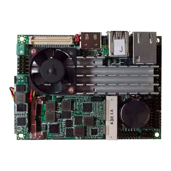
Chapter 1 <Introduction> 1.1 <Product Overview> The LP-173 motherboard is design based on Intel® Celeron® Processor J1900 / N2930 and Intel® Atom Processor E3845, delivering outstanding compute, graphical, and media performance while operating in an extended range of thermal conditions. The SoC bases on the Silvermont microarchitecture, utilizing Intel’s industry-leading 22nm... -
Page 7: Product Specification
LP-173 User’s Manual 1.2 <Product Specification> General Specification Form Factor PICO-ITX miniboard Intel® Processor J1900/N2930/E3845, package type FCBGA1170 Memory 1 x DDR3L (support 1.35V) 1066/1333 SO-DIMM up to 8GB System reset programmable watchdog timer with 1 ~ 255 sec./min. of... -
Page 8: Mechanical Drawing
LP-173 User’s Manual 1.3 <Mechanical Drawing>... -
Page 9: Block Diagram
LP-173 User’s Manual 1.4 <Block Diagram>... -
Page 10: Chapter 2
LP-173 User’s Manual Chapter 2 <Hardware Setup> 2.1 <Connector Location>... -
Page 11: Jumper Reference
LP-173 User’s Manual 2.2 <Jumper Reference> Jumper Function JRTC CMOS Operating/Clear Setting AT/ATX Mode Setting JVLCD LCD Panel Voltage Setting JMSATA Mini Card1 mSATA Setting 2.3 <Connector Reference> 2.3.1 <Internal Connector> Connector Function SO-DIMM 204 -pin DDR3L SO-DIMM SDRAM slot... -
Page 12: Memory Setup
LP-173 User’s Manual 2.4 <Memory Setup> The board provide 204-pin DDR3L SO-DIMM to support 1066/1333MHz up to 8GB. Support Non-ECC, unbuffered memory only 2.5 <CMOS & ATX Setup> The board’s data of CMOS can be setting in BIOS. If the board refuses to boot due to inappropriate CMOS settings, please remove battery to clear (reset) the CMOS to its default values. -
Page 13: Sata Interface
LP-173 User’s Manual 2.6 <SATA Interface> Based on SOC, the board provides one Serial ATAII interfaces with up to 300MB/s of transfer rate. 2.7 <LAN Interface> The board integrates with one Intel® I210-AT controller, The Intel Gigabit Ethernet supports triple speed of 10/100/1000Base-T, with IEEE802.3 compliance. -
Page 14: Cn_Lvds
LP-173 User’s Manual Connector: CN_CRT Type: onboard 16-pin connector for CN_CRT connector pitch 2.00mm Signal Signal -CRTATCH IOGND1 IOGND1 IOGND1 -CRTATCH 5VCDA 5HSYNC 5VSYNC 5VCLK 2.8.2 <CN_LVDS> The board provides one 40-pin LVDS connector for 18 bit or 24bit single channel panel, with one LCD backlight inverter connector and one jumper for panel voltage setting. - Page 15 LP-173 User’s Manual Connector: CN_INV Type: 5-pin Inverter power connector Connector model: molex_53261-5pin or compatible Description +12V Enable Jumper: JVLCD Type: 3-pin Power select jumper Description +3.3V Default setting Connector: CN_LVDS Type: onboard 20-pin connector for LVDS connector Type: onboard 40-pin connector for LVDS connector Connector model: HIROSE DF13-40DP-1.25V or compatible...
- Page 16 LCD Installation Guide: Preparing the LP-173, LCD panel and the backlight inverter You would need a LVDS type cable. Panel side...
- Page 17 LP-173 User’s Manual To connect all of the devices well.After setup the devices well, you need to select the LCD panel type in the BIOS. The panel type mapping is list below: If you want to used the LCD panel display when the boot , please go to the BIOS setup.
- Page 18 LP-173 User’s Manual Step2. click IGD Boot Type > LVDS2 BIOS panel type selection form (BIOS Version:1.0) Single / Dual channel Single / Dual channel Output format Output format 640 x 480 1680 x 1050 800 x 600 1920 x 1200...
-
Page 19: Onboard Audio Interface
AGND MIC2_R AVCC FP_OUT_R MIC2_JD SENSE_B FP_OUT_L LINE2_JD 2.10 <USB 3.0 and USB 2.0Interface> LP-173 integrates 1 x USB3.0 and 3 x USB2.0, The specifications are listed below: Interface USB3.0 USB2.0 Transfer Rate Up to 5Gb/s Up to 480Mb/s Voltage... - Page 20 LP-173 User’s Manual Connector: CN_USB (USB2.0) Type: 10-pin (5 x 2) header for USB Port Description Description Data0- Data1- Data0+ Data1+ Ground Ground Ground The USB3.0 port need to Install USB 3.0 eXtensible Host Controller Driver and enable xHCI Mode.
- Page 21 LP-173 User’s Manual Step3. enable “xHCI Mode” and push “F10” to save configuration. Restart your computer. Step4. If you enable xHCI Mode , USB 2.0 and USB 3.0 ports can’t use without drive. We recommend that you connect PS/2 mouse / keyboard installing USB 3.0 driver.
- Page 22 LP-173 User’s Manual Step6. Lastly, the “Setup Complete” screen appears so click “Finish” to restart your computer.
-
Page 23: Serial Port Jumper Setting
LP-173 User’s Manual 2.11 <Serial Port Jumper Setting > The board provides two RS232 serial ports Connector: CN_COM1/2 Type: 20-pin (5 x 2) 1.27mm x 2.54mm-pitch header for COM1/2 Description Description MDCD1- MSIN1- MSO1- MDTR1- MDSR1- MRTS1- MCTS1- MRI1- MDCD2-... -
Page 24: Power & Fan Connector
LP-173 User’s Manual 2.12 <Power & FAN Connector > The board requires DC input with 2-pin header, the input voltage range is from 6V to 27V. 2.12.1 <Power Input> Connector: DC_IN Type: 2-pin header Description Description Ground +27V 2.12.2 <Power Output>... -
Page 25: Fan Connector
LP-173 User’s Manual 2.12.3 <Fan Connector> Connector: SYSFAN Type: 3-pin fan wafer connector Description Description Description Ground +12V SYSFAN Connector: CPUFAN Type: 3-pin fan wafer connector Description Description Description Ground +12V CPUFAN... -
Page 26: Indicator And Switch
LP-173 User’s Manual 2.13 <Indicator and Switch> The JFRNT provides front control panel of the board, such as power button, reset and beeper, etc. Please check well before you connecting the cables on the chassis. Connector: JFRNT Type: onboard 10-pin (2 x 5) 2.54-pitch header... -
Page 27: Pcie Mini Card
LP-173 User’s Manual 2.14 < PCIE Mini Card > The board provides one PCIE mini card socket Jumper: JMSATA Type: onboard 3-pin header MINI_CARD Mode JMSATA Supply mSATA MINI_CARD Default setting... -
Page 28: Chapter 3
LP-173 User’s Manual Chapter 3 <BIOS Setup> The motherboard uses the Phoenix BIOS for the system configuration. The Phoenix BIOS in the single board computer is a customized version of the industrial standard BIOS for IBM PC AT-compatible computers. It supports Intel® x86 and compatible CPU architecture based processors and computers. -
Page 29: Appendix A
LP-173 User’s Manual Appendix A <I/O Port Pin Assignment> A.1 <SATA Port> Connector: SATA Type: 10-pin header for SATA Port Description Description Ground Ground Ground Ground A.2 <LAN Port> Connector: RJ45 Type: RJ45 connector with LED on rear panel Description TRD0+ TRD0- TRD1+ TRD2+ TRD2- TRD1- TRD3+ TRD3- A.3 <LPC Port>... -
Page 30: A.4
LP-173 User’s Manual A.4 <GPIO Port> The board provides a programmable 8-bit digital I/O interface; you can use this general purpose I/O port for system control like POS or KIOSK. The GPIO is an Open-drain output TTL-level input. Output:Open-drain, Most applications need use an external pull-up resistor. -
Page 31: Appendix B
LP-173 User’s Manual Appendix B <Flash BIOS> B.1 BIOS Auto Flash Tool The board is based on Phoenix BIOS and can be updated easily by the BIOS auto flash tool. You can download the tool online at the address below: LE-37D Flash Tool B.2 Flash Method... -
Page 32: Appendix C
LP-173 User’s Manual 4. Type the ” fpt64.efi -y -f xxx.bin” command to start flash BIOS processes. ( xxx.bin means the BIOS file that you want to update) 5. When it finished all update processes, restart the system. Any question about the BIOS re-flash please contact your distributors or visit the web-site at below: http://www.commell.com.tw/support/support.htm... -
Page 33: Appendix D
LP-173 User’s Manual Appendix D <Programming Watchdog Timer > The watchdog timer makes the system auto-reset while it stops to work for a period. The integrated watchdog timer can be setup as system reset mode by program. Timeout Value Range... -
Page 34: Contact Information
Taiwan Commate Computer Inc. 19F., No.94, Sec. 1, Xintai 5 Rd., Xizhi Dist., New Taipei City Address 22102, Taiwan +886-2-26963909 +886-2-26963911 Website http://www.commell.com.tw info@commell.com.tw (General Information) E-Mail tech@commell.com.tw (Technical Support) Facebook https://www.facebook.com/pages/Taiwan-Commate-Computer-Inc/547993955271899 Twitter https://twitter.com/Taiwan_Commate Commell is our trademark of industrial PC division...
Need help?
Do you have a question about the LP-173 and is the answer not in the manual?
Questions and answers