Table of Contents
Advertisement
Quick Links
Serial Number Location
S E R I A L
1 2 3 4 5 6 7 8
Record your Serial number
and purchase date here:
S/N __________________
PURCH.DATE:_________
DEALER:______________
______________________
______________________
Model No. F605
BODYCRAFT
a division of Recreation Supply Inc.
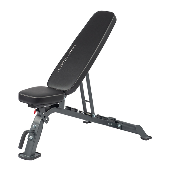
F605 FLAT / INCLINE / DECLINE
UTILITY BENCH
OWNERS MANUAL
Recreation Supply, Inc.
7699 Green Meadows Dr.
Lewis Center, OH 43035
Advertisement
Table of Contents

Related Manuals for BodyCraft F605


Summary of Contents for BodyCraft F605
- Page 1 F605 FLAT / INCLINE / DECLINE UTILITY BENCH OWNERS MANUAL Serial Number Location S E R I A L 1 2 3 4 5 6 7 8 Record your Serial number and purchase date here: S/N __________________ PURCH.DATE:_________ DEALER:______________ ______________________ ______________________ Model No.
- Page 2 8. Make certain all cables are seated within the pulleys before every use. 9. Exercise with care to avoid injury. 10. If you are unsure about the proper use of the BODYCRAFT F605 Bench call your local BODYCRAFT dealer or our customer service department.
- Page 3 F605 Bench Assembly Parts List NOTE: IF A PART IS MISSING, IT LIKELY HAS BEEN PRE-INSTALLED FOR QUALITY CONTROL PURPOSES. PLEASE PROCEED WITH ASSEMBLY. *Parts images are not to scale. (1) MAIN (2) REAR FRAME STABILIZER (4) SEAT ADJUSTER (5) HANDLE BAR (12) BACK PAD (3) BACK SUPPORT &...
- Page 4 Recommended Tools Utility Knife (To cut packaging and banding) Ratchet with 9/16" and 3/4" Sockets 9/16" and 3/4" Combination Wrenches Adjustable Wrench Rubber Mallet Assemble Main Frame NOTE: Before installing the plastic parts, please allow them to acclimate to room temperature or they may be damaged. CAREFULLY install all plastic components with Rubber Mallet.
- Page 5 A3 Assemble Pad Supports 3. Attach Back Pad Support (3) and Seat Adjuster (4) to the Main Frame (1) using two 1/2" X 5" Hex Bolts (19) and two 1/2" Nylon Nuts (27). Install two 45 X 75mm End Caps (9) to the Back Pad Support (3) and Seat Adjuster (4).
- Page 6 A4 Assemble Pads 4. Attach Back Pad (12) to the Back Support (3) using two 3/8" X 2-3/4" Hex Bolts (23) and two 3/8" Washers (26). Attach Seat Pad (13) to the Seat Pad Support (4) using two 3/8" X 2-3/4" Hex Threaded Bolts (23) and two 3/8" Washers (26).
- Page 7 EXPLODED VIEW 25 27...
- Page 8 COMPLETE PARTS CHART NO. DESCRIPTION QTY. MAIN FRAME REAR STABILIZER BACK SUPPORT SEAT ADJUSTER HANDLE BAR BACK ADJUSTER FOAM GRIP BRACE 45 X 75mm END CAP 1-1/2" SQ. END PLUG KNOB BACK PAD SEAT PAD POP PIN BUSHING LARGER RUBBER BRACKET SMALLER RUBBER BRACKET WHEEL 1/2"...
Need help?
Do you have a question about the F605 and is the answer not in the manual?
Questions and answers