Table of Contents
Advertisement
Quick Links
Advertisement
Table of Contents

Subscribe to Our Youtube Channel
Related Manuals for Air Live SA-102


Summary of Contents for Air Live SA-102
-
Page 1: User Manual
SA-102 Smart In Wall Dual Switch User Manual... - Page 2 This product contains some codes from GPL. In compliance with GPL agreement, AirLive will publish the GPL codes on our website. Please go to www.airlive.com and go to the "Support->GPL" menu to download source code. All Trademarks are properties of their respective holders. AirLive SA-102 User Manual...
- Page 3 To return your used device, please use the return and collection systems or contact the retailer where the product was purchased. They can take this product for environmental safe recycling. AirLive SA-102 User Manual...
-
Page 4: Table Of Contents
1.1 Adding to Z-Wave TM Network ............1 1.2 Auto Inclusion ..................2 1.3 LED Indication ................... 3 1.4 Choosing a Suitable Location ............3 1.5 Installation ..................4 1.6 Programming ..................4 1.7 Troubleshooting ................19 1.8 Specification ..................20 AirLive SA-102 User Manual... -
Page 5: Overview
When first power is applied, its LED flashes on and off alternately and repeatedly at 0.5 second intervals. It implies that it has not been assigned a node ID and start auto inclusion. AirLive SA-102 User Manual... -
Page 6: Auto Inclusion
2 seconds will enter lost or otherwise inoperable. inclusion mode. Within 1 second, press On/Off button again for 5 seconds. IDs are excluded. LED 0.5s On, 0.5s Off (Enter auto inclusion) AirLive SA-102 User Manual... -
Page 7: Led Indication
State Type LED Indication Normal Whatever we switch On and off of the SA-102 by S1 S2 or On/Off button or RF command, the LED will lights up 1 second and then off. No node ID Under normal operation, when the Switch has not been allocated a node ID, the LED flashes on and off alternately at 2-second intervals. -
Page 8: Installation
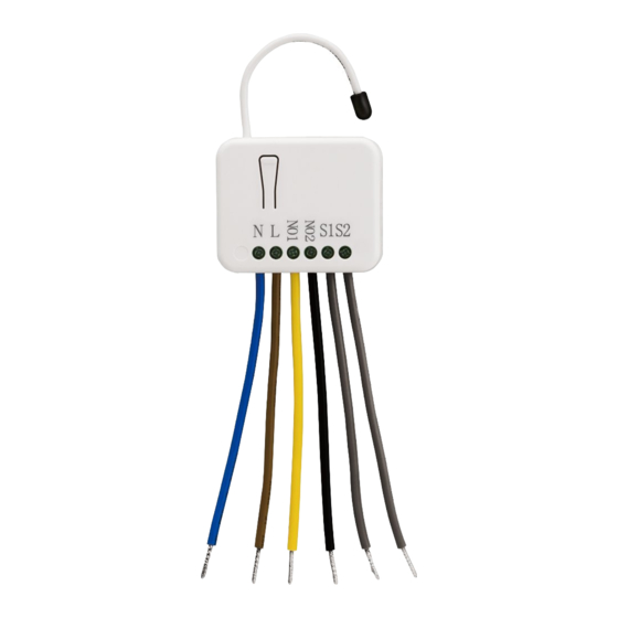
Put the in wall switch into a wall box and connect the AC power wire L, N to in wall switch connector L, N. Connect the wall switch to the SA-102 as picture. To manually turn ON the Switch, press and release the On/Off button. The LED will light ON for 1 second, and the load plugged into the Switch will also turn ON. - Page 9 For group 1, the Switch will report (1) ON/OFF status of Relay1 and Relay2 (2) Instant Power Consumption (Watt) of Relay1 and Relay2 (3) Accumulated Power Consumption (KWh) of Relay1 and Relay2 to Z-Wave Controller. For group 2, the Switch will report (1) ON/OFF status of Relay1 (2) Instant Power AirLive SA-102 User Manual...
- Page 10 = 1,Scale = 0x02,Size = 4,Meter Value(W) ] 1.6.2.3. Overload alarm report command When SA-102 detect the overload, it will send Alarm Report to the correspond Group。 The content of Alarm Report Alarm report command: [Command_Class_Alarm, Alarm_Report, Alarm Type = 0x08,...
- Page 11 When receiving Meter Get Command, it will report Meter Report Command to the node asked. Meter Get Command: [Command Class Meter, Meter Get, Scale =0x04(V)] Meter Report Command:[Command Class Meter,Meter Report,Rate Type = 0x01, Meter Type = 0x01,Precision = 1,Scale = 0x04,Size = 2, Meter Value(V)] AirLive SA-102 User Manual...
- Page 12 Size = 1 (1 Byte of PF) Meter Value 1 = 0x63(PF) (It means that the load power factor is 0.99) 1.6.4. Multi Channel Command Class Version 3 SA-102 also support Muti Channel command class (version 3), which include INARY_SWITCH_GET, BINARY_SWITCH_SET, BASIC_GET, BASIC_SET, METER_SUPPORTED_GET, METER_RESET, METER_GET You may control or get report from 3 endpoints of SA-102.
- Page 13 You may get the ON/OFF state from every endpoint, when endpoint set to 1, SA-102 will reply state of Relay1. If endpoint set to 2, SA-102 will reply state of Relay2. If endpoint set to 3, SA-102 will reply ON (0xFF) when either Relay 1 or Relay2 is ON, report OFF (0x00) when both Relay 1 and Relay2 are OFF.
- Page 14 (Switch_Binary_Set = 0x01) (ON=0xFF , OFF=0x00) Parameter 1 = 0x00 1.6.4.3. METER_SUPPORTED_GET: This command is to ask the endpoint of SA-102 what kind of meter data can be reported. The example show how to get the meter report type COMMAND_CLASS_MULTI_CHANNEL MULTI_CHANNEL_CMD_ENCAP (this is the endpoint of command inquirer here we assume endpoint is 1,if the...
- Page 15 ( Command_Class_Meter_V3 = 0x32) Command Class = 0x32 ( Meter_Reset = 0x05) Command =0x05 1.6.4.5. METER_GET Using meter get command to get the KWH, W, V, I, PF from endpoint of SA-102 1.6.4.5.1. Get KWH from endpoint Meter_GET example COMMAND_CLASS_MULTI_CHANNEL MULTI_CHANNEL_CMD_ENCAP (this is the endpoint of command inquirer, here we assume endpoint is 5,if the...
- Page 16 ( Command_Class_Meter_V3 = 0x32) Command =0x01 (Meter_Get = 0x01) Parameter 1 = 0x10 (Scale = W = 0x02) SA-102 Instant Power Consumption (W) Report example: COMMAND_CLASS_MULTI_CHANNEL MULTI_CHANNEL_CMD_ENCAP Source End Point = 0x03 (Meter report = Endpoint3) (Bit Address+Destination End Point = 0x05) (Bit Address =0;Destination End Point =...
- Page 17 ( Command_Class_Meter_V3 = 0x32) Command =0x01 (Meter_Get = 0x01) Parameter 1 = 0x20 (Scale = V = 0x04) SA-102 AC load Voltage report example: COMMAND_CLASS_MULTI_CHANNEL MULTI_CHANNEL_CMD_ENCAP Source End Point = 0x03 (Meter report = Endpoint3) (Bit Address+Destination End Point = 0x05) (Bit Address =0;Destination End Point =...
- Page 18 ( Command_Class_Meter_V3 = 0x32) Command =0x01 (Meter_Get = 0x01) Parameter 1 = 0x28 (Scale = A = 0x05) SA-102 AC load current (I) example: COMMAND_CLASS_MULTI_CHANNEL MULTI_CHANNEL_CMD_ENCAP Source End Point = 0x03 (Meter report = Endpoint3) (Bit Address+Destination End Point = 0x05) (Bit Address =0;Destination End Point...
- Page 19 32767s RF off 0 : Switch off command 1 : Ignore mode 2 : Switch toggle 3 : Switch on Existence of 1 : Endpoint3 exist Endpoint3 2 : No Endpoint3 1.6.5.1. att Meter Report Period AirLive SA-102 User Manual...
- Page 20 1. Overview If the setting is configured for 1hour (set value =720), the SA-102 will report its instant power consumption every 1 hour to the node of correspond Group. The maximum interval to report its instant power consumption is 45 hours (5s*32767/3600=45hr).
- Page 21 This is a warning when the current of load over the preset threshold value, if the setting value is 750, when the load current of Relay1 or Relay2 over this value, SA-102 will send current meter report to the node of correspond Group, the Range of the setting value is from 10 to 750, and the default value is 750.
- Page 22 Multi-Channel Command is a good way to control relay1 and relay2 of SA-102 individually. The endpoint3 of SA-102 is related to both relay1 and relay2. In some condition it becomes redundant in Multi-Channel Command Class. When the Existence of Endpoint3 is set as 2, the endpoint3 will be disabled.
-
Page 23: Troubleshooting
Same frequency interference Wait for a while to re-try Detector cannot control the Switch LED keep flashing, but Overload occurs Remove the load attached cannot control or check max. load cannot exceed 7.5A(Resistive load) AirLive SA-102 User Manual... -
Page 24: Specification
Operating Temperature 0°C ~ 40°C Frequency Range SA-102-1: 868.40MHz; 869.85MHz(EU) / SA-102-2: 908.40MHz; 916.00MHz(USA/Canada) / SA-102-3: 922.5MHz/ 923.9MHz/ 926.3MHz (Taiwan/JP) Specifications are subject to change and improvement without notice. OvisLink Corp., http://www.airlive.com/ TEL: +886 2 2218 6888 FAX: +886 2 2918 6988...
Need help?
Do you have a question about the SA-102 and is the answer not in the manual?
Questions and answers