Max TA551B/16-11 Operating And Maintenance Manual
Hide thumbs
Also See for TA551B/16-11:
- Operating instructions manual (29 pages) ,
- Operating instructions manual (36 pages)
Advertisement
Quick Links
TA551B/16-11
PNEUMATIC STAPLER
AGRAFEUSE PNEUMATIQUE
MÁQUINA GRAPADORA NEUMÁTICA
OPERATING AND MAINTENANCE MANUAL
MANUEL D'UTILISATION ET D'ENTRETIEN
MANUAL DE OPERACIONES Y MANTENIMIENTO
BEFORE USING THIS TOOL, STUDY THIS MANUAL TO ENSURE SAFETY WARNING AND IN-
STRUCTIONS.
KEEP THESE INSTRUCTIONS WITH THE TOOL FOR FUTURE REFERENCE.
WARNING
AVANT D'UTILISER CET OUTIL, LIRE CE MANUEL ET LES CONSIGNES DE SÉCURITÉ AFIN DE
GARANTIR UN FONCTIONNEMENT SÛR.
CONSERVER CE MANUEL EN LIEU SÛR AVEC L'OUTIL AFIN DE POUVOIR LE CONSULTER UL-
TÉRIEUREMENT.
AVERTISSEMENT
ANTES DE UTILIZAR ESTA HERRAMIENTA, LEA DETENIDAMENTE ESTE MANUAL PARA FAMILIARIZARSE CON
LAS ADVERTENCIAS E INSTRUCCIONES DE SEGURIDAD.
CONSERVE ESTAS INSTRUCCIONES JUNTO CON LA HERRAMIENTA PARA FUTURAS CONSULTAS.
ADVERTENCIA
Advertisement

Related Manuals for Max TA551B/16-11


Summary of Contents for Max TA551B/16-11
- Page 1 TA551B/16-11 PNEUMATIC STAPLER AGRAFEUSE PNEUMATIQUE MÁQUINA GRAPADORA NEUMÁTICA OPERATING AND MAINTENANCE MANUAL MANUEL D’UTILISATION ET D’ENTRETIEN MANUAL DE OPERACIONES Y MANTENIMIENTO BEFORE USING THIS TOOL, STUDY THIS MANUAL TO ENSURE SAFETY WARNING AND IN- STRUCTIONS. KEEP THESE INSTRUCTIONS WITH THE TOOL FOR FUTURE REFERENCE.
- Page 2 INDEX INDEX ÍNDICE ENGLISH Page to 13 FRANÇAIS Page to 25 ESPAÑOL Page to 37 DEFINITIONS OF SIGNAL WORDS WARNING: Indicates a potentially hazardous situation which, if not avoided, could result in death or serious injury. CAUTION: Indicates a potentially hazardous situation which, if not avoided, may result in mi- nor or moderate injury.
-
Page 3: Table Of Contents
ENGLISH OPERATING AND MAINTENANCE MANUAL INDEX 1. GENERAL SAFETY WARNINGS ............3 2. SAFETY WARNING ................4 3. SPECIFICATIONS AND TECHNICAL DATA ........7 4. AIR SUPPLY AND CONNECTIONS............8 5. INSTRUCTIONS FOR OPERATION............9 6. MAINTAIN FOR PERFORMANCE ............13 7. STORAGE ..................13 8. TROUBLE SHOOTING/REPAIRS .............13 BEFORE USING THIS TOOL, STUDY THIS MANUAL TO ENSURE SAFETY WARNING AND IN- STRUCTIONS. -
Page 4: Safety Warning
Thinner Gasoline PLACE THE DISCHARGE OUTLET ON THE WORK SUR- DO NOT OPERATE THE TOOL NEAR A FLAMMABLE FACE PROPERLY SUBSTANCE Failure to place the discharge outlet of the nose in a proper Never operate the tool near a flammable substance (e.g., manner can result in a fastener flying up and is extremely thinner, gasoline, etc.). - Page 5 14. REMOVING THE FASTENERS AFTER COMPLETING OPERATION If fasteners are left in the magazine after the completion of operation, there is the danger of a serious accident occur- ring prior to the resumption of operation, should the tool be handled carelessly, or when connecting the air fitting. For this reason, always remove all fasteners remaining in the magazine after completion of the operation.
- Page 6 Keep the tool in a dry place out of reach of chil- dren when not in use. Do not use the tool without Safety Warning label. Do not modify the tool from original design or function without approval by MAX CO., LTD.
-
Page 7: Specifications And Technical Data
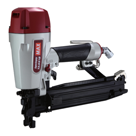
8 Trigger Lock Dial 9 Staple Removal Lever 0 Pusher a Click Lever b Rafter Hook c Swivel Joint TOOL SPECIFICATIONS PRODUCT NO. TA551B/16-11 HEIGHT 11-3/8″ (288.5 mm) WIDTH 3-1/4″ (84 mm) LENGTH 14″ (356 mm) WEIGHT 5.5 lbs. (2.5 kg) RECOMMENDED 70 to 100 p.s.i. -
Page 8: Air Supply And Connections
4. AIR SUPPLY AND CONNEC- TOOL AIR FITTINGS: TIONS This tool uses a 1/4″ N.P.T. male plug. The inside diameter should be .28″ (7 mm) or larger. The fitting must be capable of discharging tool air pressure when disconnected from the air supply. RECOMMENDED OPERATING PRESSURE: 70 to 100 p.s.i. -
Page 9: Instructions For Operation
HOSES: Hose has a min. ID of 1/4″ (6 mm) and max. length of no more than 17″ (5 meters). The supply hose should contain a fitting that will provide “quick disconnecting”... - Page 10 STAPLE LOADING TEST OPERATION Adjust the air pressure at 70 p.s.i. (5 bar) and connect the air supply. Without touching the trigger, depress the contact arm against the work-piece. Pull the trigger. (The tool must fire the fastener.) With the tool off the work-piece, pull the trigger. Then depress the contact arm against the work-piece.
- Page 11 DRIVING FASTENERS DRIVING DEPTH ADJUSTMENT CONTACT FIRE OPERATION (CONTACT TRIP) For contact fire operation, hold the trigger and depress the con- tact arm against the work surface. Hex. bar wrench PROCEDURE Hold the trigger. Depress the contact arm. SINGLE FIRE OPERATION (ANTI-DOUBLE FIRE MECHANISM AND SEQUENTIAL TRIP) For single fire operation, depress the contact arm against the work surface and pull the trigger.
- Page 12 TRIGGER LOCK MECHANISM The tool is equipped with a trigger lock mechanism. Push and ro- tate the trigger LOCK to the trigger UNLOCK position before driv- ing staples. Trigger lock dial Staple removal lever Take out the staples from the inside of the magazine. Release the staple removal lever and open the door.
-
Page 13: Maintain For Performance
The troubleshooting and/or repairs shall be carried out only by rust and wear, and results in a poor operating performance. the MAX CO., LTD. authorised distributors or by other specialists. The hose length between airset and tool should be no long- er than 5 m since a longer length results in a reduction in air pressure.
Need help?
Do you have a question about the TA551B/16-11 and is the answer not in the manual?
Questions and answers