Advertisement
Quick Links
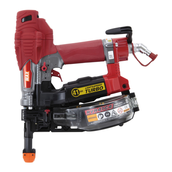
HVR41G4(CE)
COLLATED SCREW FASTENING SYSTEM
MAGAZINSCHRAUBER
SYSTÈME DE FIXATION PAR VIS
ASSEMBLÉES EN BANDE
SISTEMA DI FISSAGGIO VITI A NASTRO
SISTEMA DE APRIETE DE TORNILLO EN
SECUENCIA
OPERATING AND MAINTENANCE MANUAL
MANUEL D'UTILISATION ET D'ENTRETIEN
MANUALE DI FUNZIONAMENTO E MANUTENZIONE
MANUAL DE OPERACIONES Y MANTENIMIENTO
BEFORE USING THIS TOOL, STUDY THIS MANUAL TO ENSURE SAFETY WARNING AND IN-
STRUCTIONS.
KEEP THESE INSTRUCTIONS WITH THE TOOL FOR FUTURE REFERENCE.
WARNING
LESEN SIE VOR INBETRIEBNAHME DES GERÄTES DIE GEBRAUCHS- UND SICHERHEITSHINWEISE.
BITTE BEWAHREN SIE DIE GEBRAUCHS- UND SICHERHEITSHINWEISE AUF, DAMIT SIE AUCH
SPÄTER EINGESEHEN WERDEN KÖNNEN.
WARNUNG
AVANT D'UTILISER CET OUTIL, LIRE CE MANUEL ET LES CONSIGNES DE SÉCURITÉ AFIN DE
GARANTIR UN FONCTIONNEMENT SÛR.
CONSERVER CE MANUEL EN LIEU SÛR AVEC L'OUTIL AFIN DE POUVOIR LE CONSULTER UL-
TÉRIEUREMENT.
AVERTISSEMENT
PRIMA DI USARE QUESTO STRUMENTO, STUDIARE IL MANUALE PER PRENDERE ATTO DELLE
AVVERTENZE E DELLE ISTRUZIONI PER LA SICUREZZA.
TENERE QUESTE ISTRUZIONI INSIEME ALLO STRUMENTO PER CONSULTAZIONI FUTURE.
ATTENZIONE
ANTES DE UTILIZAR ESTA HERRAMIENTA, LEA DETENIDAMENTE ESTE MANUAL PARA FAMILIARIZARSE CON
LAS ADVERTENCIAS E INSTRUCCIONES DE SEGURIDAD.
CONSERVE ESTAS INSTRUCCIONES JUNTO CON LA HERRAMIENTA PARA FUTURAS CONSULTAS.
ADVERTENCIA
BETRIEBSANLEITUNG
Original Language English
Advertisement

Related Manuals for Max HVR41G4


Summary of Contents for Max HVR41G4
- Page 1 HVR41G4(CE) COLLATED SCREW FASTENING SYSTEM MAGAZINSCHRAUBER SYSTÈME DE FIXATION PAR VIS ASSEMBLÉES EN BANDE SISTEMA DI FISSAGGIO VITI A NASTRO SISTEMA DE APRIETE DE TORNILLO EN SECUENCIA OPERATING AND MAINTENANCE MANUAL BETRIEBSANLEITUNG MANUEL D'UTILISATION ET D'ENTRETIEN MANUALE DI FUNZIONAMENTO E MANUTENZIONE...
- Page 2 ITALIANO Page to 58 ESPAÑOL Page to 72 www.max-europe.com DEFINITIONS OF SIGNAL WORDS WARNING: Indicates a hazardous situation which, if not avoided, could result in death or se- rious injury. CAUTION: Indicates a hazardous situation which, if not avoided, could result in minor or mod- erate injury.
-
Page 3: Table Of Contents
ENGLISH OPERATING AND MAINTENANCE MANUAL INDEX 1. NAME OF PARTS ................3 2. GENERAL SAFETY WARNINGS ............4 3. SAFETY WARNING ................4 4. SPECIFICATIONS AND TECHNICAL DATA ........7 5. AIR SUPPLY AND CONNECTIONS............7 6. INSTRUCTIONS FOR OPERATION............8 7. HOW TO REPLACE THE BIT............14 8. -
Page 4: General Safety Warnings
2. GENERAL SAFETY WARNINGS KEEP HANDS AND BODY AWAY FROM THE DIS- CHARGE OUTLET When loading and using the tool, never place a hand or any part of body in fastener discharge area of the tool. It is very dangerous to hit the hands or body by mistake. WARNING TO AVOID SEVERE PERSONAL INJURY OR PROPERTY DAMAGE... - Page 5 Thinner Gasoline DO NOT TOUCH THE TRIGGER UNLESS YOU INTEND TO DRIVE A FASTENER DO NOT OPERATE THE TOOL NEAR A FLAMMABLE Whenever the air supply is connected to the tool, never SUBSTANCE touch the trigger unless you intend to drive a fastener into Never operate the tool near a flammable substance (e.g., the work.
- Page 6 For function without approval by MAX CO., LTD. this reason, always remove all fasteners remaining in the magazine after completion of the operation.
-
Page 7: Specifications And Technical Data
4. SPECIFICATIONS AND TECHNI- 5. AIR SUPPLY AND CONNEC- CAL DATA TIONS TOOL SPECIFICATIONS HEIGHT 312 mm (12-1/4") WIDTH 116 mm (1-1/2") WARNING LENGTH 300 mm (11-3/4") WEIGHT 1.9 kg (4.2 lbs.) Read section titled "SAFETY INSTRUCTIONS" RECOMMENDED 18 to 23 bar OPERATING PRESSURE (250 to 320 p.s.i.) LOADING CAPACITY... -
Page 8: Instructions For Operation
To use the tool, you al- NOTICE: ways need the special air compressor and air hose (MAX Non-side shielded spectacles and face shields alone do not pro- PowerLite Compressor and MAX PowerLite Hose). Use of high- vide adequate protection. - Page 9 WARNING Keep hands and body away from the discharge outlet when driv- ing the fasteners because of dangerous of hitting the hands or body by mistake. SCREW LOADING Door latch Door Swing magazine cover closed. Close the door. Check that latch engages. (If it does not engage, check that the screw heads are in the slot on the nose.) Open the magazine.
- Page 10 CHANGEOVER LEVER CONTACT FIRE OPERATION (CONTACT TRIP) This tool has a changeover lever mechanism, which allows opti- For contact fire operation, hold the Trigger and depress the Con- mum (drivability, speed) screwing work depending on the condi- tact Arm against the work surface. tion of the driven-side base material.
- Page 11 DRIVING DEPTH ADJUSTMENT DIAL SEQUENTIAL TRIP Identified by ORANGE TRIGGER. Adjust dial Shallow Deeper CONTACT TOP WARNING • When replacing the contact top, make sure to WARNING lock the trigger and remove the air hose. • ALWAYS disconnect air supply before Adjust- ment dial.
- Page 12 HOW TO USE SINGLE-TOUCH ADJUSTER WARNING • ALWAYS disconnect air supply before using single-touch adjuster. When it is inevitable to drive a screw slantly such as corner driving, this tool can sink under the board surface by single-touch operation. Adjuster position Screw Application Projecting...
- Page 13 TRIGGER LOCK MECHANISM discontinue use of the machine, disconnect the air supply, and send it to be repaired by a MAX Co., Ltd. authorized distributor or other specialist. Note that the relief valve is built in to the rear part of the machine body.
-
Page 14: How To Replace The Bit
Use the “TURBO DRIVER BIT B41X2” which is optionally available at the MAX Co., Ltd. authorized distributors or by other specialists. 1. HOW TO REMOVE THE BIT CAUTION •... - Page 15 2. HOW TO ASSEMBLE Cylinder O-ring Bit Assembly CAUTION • When assembling, use only the specified oil and grease. Hexagonal section PistonCap O-ring Straight Pin Main Piston Gear O-ring CAUTION • Make sure that the O-ring is not coming out of the Bit Assembly.
-
Page 16: Maintain For Performance
Order of Screws Third Second 10. TROUBLE SHOOTING/REPAIRS The troubleshooting and/or repairs shall be carried out only by the MAX CO., LTD.authorised distributors or by other specialists. First Fourth Supplement to the operating instruction According to the European Norm EN 792-13 the regulation is val- id from 01.01.2001 that all fastener driving tools with contact ac-... - Page 17 • Las características y la concepción de los productos mencionados en este manual están sujetas a modificaciones sin preaviso debido a nuestros esfuerzos continuos para mejorar la calidad de nuestros productos. Camerastraat 19 1322 BB Almere The Netherlands Phone: +31-36-546-9669 FAX: +31-36-536-3985 wis.max-ltd.co.jp/int/ (GLOBAL Site) www.max-europe.com (EUROPE Site) 4011550 140821-00/02...
Need help?
Do you have a question about the HVR41G4 and is the answer not in the manual?
Questions and answers