Table of Contents
Advertisement
Quick Links
Advertisement
Table of Contents

Related Manuals for ECS SI mPC


Summary of Contents for ECS SI mPC
- Page 1 User Manual ECS SI mPC...
-
Page 2: Regulatory Compliance Information
This device meets the government’s requirements for exposure to radio waves. This device is designed and manufactured not to exceed the emission limits for exposure to radio frequency (RF) energy set by the Federal Communications Commission of the U.S. Government, Industry Canada, and other national regulatory agencies. ECS SI mPC... - Page 3 To minimize pollution and ensure utmost protection of the global environment, please recycle it in European WEEE (waste electrical and electronic equipment) directive system or recycle system in Taiwan. Part No. Edition 1 Printed in China OCT 2015 ECS SI mPC...
- Page 4 로 가정에서 사용하는 것을 목적으로 하며, 모든 지역에서 사용할 수 있습니다. 해당 무선설비는 전파혼신 가능성이 있으므로 인명안전과 관련된 서비스는 할 수 없음 Korea Certification mark. Includes an adjacent MSIP (Ministry of Science, ICT & future planning) certification number. ECS SI mPC...
-
Page 5: Packing List
Additional Information and Assistance Additional Information and Assistance Visit the ECS websites at www.ECS.com.tw where you can find the latest information about the product. Contact your distributor, sales representative, or ECS’s customer service center for technical support if you need additional assistance. Please have the following... -
Page 6: Safety Instructions
PERSONAL INJURY! VESA mount installation should be performed by a professional technician; please contact the service technician or your retailer if you need this service. Maintenace: to properly maintain and clean the surfaces, use only the approved products or clean with a dry applicator. ECS SI mPC... -
Page 7: Table Of Contents
Powering the System ..………………………………………………………… 7 Chapter Hardware Installation ......8 Motherboard Introduction ............... 9 Installing the Motherboard .……..….…………………...….…..………..12 Chapter Using BIOS ........20 About the Setup Utility ................21 Using BIOS …………………………………………………………………… 22 Chapter Feature Inforamtion ......39 Introduction ..................... 40 ECS SI mPC... -
Page 8: System Information
Chapter System Information... -
Page 9: Introduction
116.6*112*45.6 mm 0.595L mPC-AH 116.6*112*55.6 mm 0.726L Optional Device Storage type: 2.5” HDD, Half-size mini-PCIe mSATA SSD, SATADOM WLAN: 802.11b/g/n + Bluetooth4.0 NFC: URAT interface Wireless Charger: Compatible with Qi (Not Support) Speaker: Internal speaker 1Wx2 ECS SI mPC... -
Page 10: Cleaning/Disinfecting
During normal use ECS SI mPC may become solied and should, therefore, be cleaned regularly. Steps: Wipe ECS SI mPC with a clean cloth that has been moistened in the cleaning solution. Prepare agent per manufacturer’s instructions or hospital protocol. Wipe thoroughly with a clean cloth. -
Page 11: Getting Started
Chapter Getting Started... -
Page 12: System Tour
Wireless charger LED (Optional) (Power transfer Green blink, Fault Red blink) Wireless charger/NFC (Optional) HDD LED Power Button Figure 2.1 Top View Speaker (Optional) Figure 2.2 Bottom View Kensington Lock Figure 2.3 Side View ECS SI mPC... -
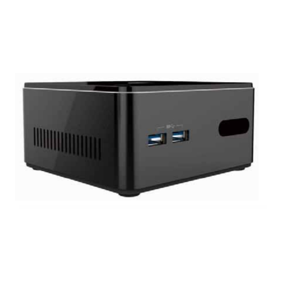
Page 13: Figure 2.4 I/O Side View
IR sensor USB 3.0 DC Jack Thermal opening Combo Audio Jack HDMI (Mic In& Line out) RJ45 port USB 2.0 Figure 2.4 IO Side View Install the VESA Mount ECS SI mPC... -
Page 14: Distribution Description
Distri ution Description The operating system is based on Windows .1 64bit / FreeDOS. owering the System Connecting a 12 adapter to the DC-In ack, the system will start up automatically. DC-In DC-In Figure 1: Location of DC-In ack. ECS SI mPC... -
Page 15: Hardware Installation
Chapter ardware Installation... -
Page 16: Motherboard Introduction
Introduction other oard Components ECS SI mPC... - Page 17 1 M.2 slot (half card supports mSATA, USB & PCIe signal) . LED BAR Logo LED connector . SATA Serial ATA connector . SATA PWR SATA power connector 10. CLR CMOS Clear CMOS umper 11. NFC NFC connector 12. SODIMM 204-pin DDR3 SDRAM SO-DIMM ia a ECS SI mPC...
- Page 18 Connect the display device to the HDMI port. . DC 12V ac Connect the DC IN ack to the power adapter. . CI It is coustomer IR sensor. SB3. orts Use the USB 3.0 ports to connect USB 3.0 devices. ECS SI mPC...
-
Page 19: Installing The Motherboard
2. Installing the mother oard in a Chassis 1. Aim four locating holes of the BTM-S motherboard. 2. Use four screws to secure the motherboard. Do not over- ghten the screws as this can stress the motherboard. ECS SI mPC... - Page 20 Refer to the following to install the memory modules. Install the DIMM module into the slot and press it firmly down until it seats correctly. Check that the cutouts on the DIMM module edge connector match the notches in the DIMM slot. SODI ECS SI mPC...
- Page 21 The mini PCI Express x1 slot is for extending usage which supports half-card, and it supports mSATA, USB & PCIe signal. Before installing an add on card, check the documentation for the card carefully. If the card is not Plug and Play, you may have to manually configure the card before installation. ECS SI mPC...
- Page 22 Conne tin tional e i es Refer to the following for information on connecting the motherboard’s devices. 1. F System cooling fan connector Connect the system cooling fan to the FAN connector. ECS SI mPC...
- Page 23 2. B T1 Battery connector 3. S Spea er connector ECS SI mPC...
- Page 24 D connector ECS SI mPC...
- Page 25 . S T Serial T connector . S T S T power connector ECS SI mPC...
- Page 26 8. NFC: NFC connector ECS SI mPC...
Need help?
Do you have a question about the SI mPC and is the answer not in the manual?
Questions and answers