Table of Contents
Advertisement
Copyright
This publication, including all photographs, illustrations and software, is protected
under international copyright laws, with all rights reserved. Neither this manual, nor
any of the material contained herein, may be reproduced without written consent of
the author.
Version 1.0
Disclaimer
The information in this document is subject to change without notice. The
manufacturer makes no representations or warranties with respect to the contents
hereof and specifically disclaims any implied warranties of merchantability or fitness
for any particular purpose. The manufacturer reserves the right to revise this
publication and to make changes from time to time in the content hereof without
obligation of the manufacturer to notify any person of such revision or changes.
Trademark Recognition
®
Windows
7/8/10 are registered trademarks of Microsoft Corp.
Other product names used in this manual are the properties of their respective
owners and are acknowledged.
Federal Communications Commission (FCC)
This equipment has been tested and found to comply with the limits for a Class B
digital device, pursuant to Part 15 of the FCC Rules. These limits are designed to
provide reasonable protection against harmful interference in a residential installa-
tion. This equipment generates, uses, and can radiate radio frequency energy and, if
not installed and used in accordance with the instructions, may cause harmful inter-
ference to radio communications. However, there is no guarantee that interference
will not occur in a particular installation. If this equipment does cause harmful
interference to radio or television reception, which can be determined by turning the
equipment off and on, the user is encouraged to try to correct the interference by one
or more of the following measures:
•
Reorient or relocate the receiving antenna
•
Increase the separation between the equipment and the receiver
•
Connect the equipment onto an outlet on a circuit different from that to
which the receiver is connected
•
Consult the dealer or an experienced radio/TV technician for help
Shielded interconnect cables and a shielded AC power cable must be employed with
this equipment to ensure compliance with the pertinent RF emission limits govern-
ing this device. Changes or modifications not expressly approved by the system's
manufacturer could void the user's authority to operate the equipment.
Preface
i
Preface
Advertisement
Table of Contents

Subscribe to Our Youtube Channel
Related Manuals for ECS Liva One


Summary of Contents for ECS Liva One
- Page 1 Preface Copyright This publication, including all photographs, illustrations and software, is protected under international copyright laws, with all rights reserved. Neither this manual, nor any of the material contained herein, may be reproduced without written consent of the author. Version 1.0 Disclaimer The information in this document is subject to change without notice.
-
Page 2: Declaration Of Conformity
Declaration of Conformity This device complies with part 15 of the FCC rules. Operation is subject to the following conditions: • This device may not cause harmful interference, and • This device must accept any interference received, including interfer- ence that may cause undesired operation Canadian Department of Communications This class B digital apparatus meets all requirements of the Canadian Interference- causing Equipment Regulations. -
Page 3: Safety Instructions
Safety Instructions Your system is designed and tested to meet the latest standards of safety for informa- tion technology equipment. However, to ensure your safety, it is important that you read the following safety instructions. Setting up your system • Read and follow all instructions in the documentation before you oper- ate your system. - Page 4 Safety cautions and warnings Optical Drive Safety Information Optical drive sold with this system contains a CLASS 1 LASER PRODUCT. CAUTION: Invisible laser radiation when open. Do not stare into beam or view directly with optical instructions. WARNING: Makeing adjustments or performing procedures other than those speci- fied in the user’s manual may result in hazardous laser exposuer.
-
Page 5: Table Of Contents
T T T T T ABLE OF CONTENTS ABLE OF CONTENTS ABLE OF CONTENTS ABLE OF CONTENTS ABLE OF CONTENTS Preface Chapter 1 Introducing the PC Introduction..................1 Specification..................2 Front and Rear I/O................3 Packing Contents................5 Chapter 2 7 7 7 7 7 Installing the PC System Quick Installtion..............7 Chapter 3... - Page 6 37 37 37 37 37 Chapter 5 Trouble Shooting Start up problems during assembly..........37 Start up problems after prolong use..........38 Maintenance and care tips............38 Basic Troubleshooting Flowchart..........39...
-
Page 7: Introducing The Pc
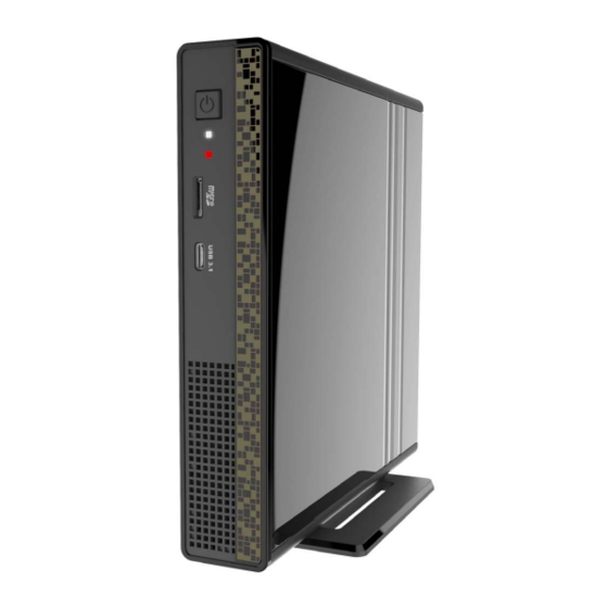
Chapter 1 Introducing the PC Introduction Thank you for choosing this 1L case of great performance and with stylish and flexible design. ® Supports LGA1151 Socket for Intel Skylake processor and a dimension of 173mm (H)* 176mm (D)* 33mm (W), 1L SFF provides the features of low power consumption (working with a 90Watt power adaptor), and space saving. -
Page 8: Specification
Specification Chipset • Intel ® H110 CPU Support ® • Supports LGA1151 Socket for Intel Skylake processor (up to 35W) Memory • 2 x SO-DIMM up to 16 GB, Dual-channel • Intel ® HD graphics from CPU Graphics • Support 4K resolution and DX12 for Intel Skylake-S Storage •... -
Page 9: Front And Rear I/O
Front and Rear I/O Press the prower button to turn the system on and 1. Power Button off. 2. Power LED This is the power LED light. 3. HDD LED This is the HDD LED light. 4. Card Reader Supports SD Card/ MMC Card/ MS Card. You can easily read phone or other files on the momery card. - Page 10 6. USB 3.0 Connectors Connecting USB 3.0 Devices. 7. Kensington This is the security lock. 8. LAN Connecting the Network. 9. HD Audio Microphone Jack/ Headphone Jack. 10. COM Port (optional) Connecting a serial port extension bracket. 11. HDMI Port Connect display device to the HDMI port.
-
Page 11: Packing Contents
Packing Contents Driver DVD Manual Power Stand USB 3.1 to USB 3.0 cable NOTE: Please contact us immediately if any of the items is damaged or missing. Introducing the PC... - Page 12 Memo Introducing the PC...
-
Page 13: Installing The Pc
Chapter 2 Installing the PC System Quick Installation 1. Connecting HDMI device. 2. Connecting VGA Monitor. (D-SUB Connector) 3. The USB connector is for attaching USB devices, such as mouse, keyboard, printer, scanner and other USB-compatible device. Installing the PC... - Page 14 4. Connecting the Network. (LAN Connector) 5. Connecting the Speakers or Headphones. (HD Audio Jack) 6. Connecting Power. (DC jack) Installing the PC...
-
Page 15: Using Bios
Chapter 3 Using BIOS About the Setup Utility The computer uses the latest “American Megatrends Inc. ” BIOS with support for Windows Plug and Play. The CMOS chip on the motherboard contains the ROM setup instructions for configuring the motherboard BIOS. The BIOS (Basic Input and Output System) Setup Utility displays the system’s configuration status and provides you with options to set system parameters. -
Page 16: Resetting The Default Cmos Values
Press the delete key to access BIOS Setup Utility. Resetting the Default CMOS Values When powering on for the first time, the POST screen may show a “CMOS Settings Wrong” message. This standard message will appear following a clear CMOS data at factory by the manufacturer. -
Page 17: Bios Navigation Keys
Some options (marked with an icon ) lead to submenus that enable you to change the values for the option. Use the cursor arrow keys to scroll through the items in the submenu. In this manual, default values are enclosed in parenthesis. Submenu items are denoted by an icon The default BIOS setting for this motherboard apply for most conditions with optimum performance. -
Page 18: Boot Priority
Language Select the language icon and press <Enter> or double click the left key of the mouse to display the screen. Then you can choose the language: English, Traditional Chinese, Simple Chinese, Russian, Korean, German, Spanish, Italian, Portuguese, Japanese. Default Select the default icon and press <Enter>... -
Page 19: Main Menu
Main Menu This menu shows the information of BIOS and enables you to set the system language, date and time. Main Advanced Chipset Tweak Security Boot Exit Choose the system default BIOS Information language System Language English System Date Wed 10/21/2015 System Time 18:10:41 ... -
Page 20: Advanced Menu
Advanced Menu The Advanced menu items allow you to change the settings for the CPU and other system. Main Advanced Chipset Tweak Security Boot Exit LAN Configuration LAN Configuration Parameters PC Health Status Power Management Setup ACPI Settings CPU Configuration ... -
Page 21: Pc Health Status
PC Health Status On motherboards support hardware monitoring, this item lets you monitor the parameters for critical voltages, temperatures and fan speeds. Main Advanced Chipset Tweak Security Boot Exit PC Health Status CPU Temperature (DTS) System Temperature CPU Fan Speed 851 RPM... -
Page 22: Power Management Setup
Power Management Setup This page sets up some parameters for system power management operation. Main Advanced Chipset Tweak Security Boot Exit About Resume by Ring Power Management Setup Resume By RING Disabled Resume By PME Disabled... -
Page 23: Acpi Settings
ACPI Settings The item in the menu shows the highest ACPI sleep state when the system enters suspend. Main Advanced Chipset Tweak Security Boot Exit ACPI Settings Select the highest ACPI sleep state the system will enter when the ACPI Sleep State S3 (Suspend to RAM) -
Page 24: Cpu Configuration
CPU Configuration This item in the menu shows the information of the CPU. Main Advanced Chipset Tweak Security Boot Exit CPU Configuration Number of cores to enable in each processor package. Intel(R) Core(TM) i5-6500T CPU @ 2.50GHz EM64T Supported Processor Speed... - Page 25 Limit CPUID Maximum (Disabled) Use this item to enable or disable the maximum CPUID value limit, you can enable this item to prevent the system from “rebooting” when trying to install Windows NT 4.0. Excute Disable Bit (Enabled) This item allows the processor to classify areas in memory by where application code can execute and where it cannot.
-
Page 26: Sata Configuration
SATA Configuration This item in the menu shows the mode of serial ATA configuration options. Main Advanced Chipset Tweak Security Boot Exit SATA Configuration Determines how SATA controller(s) operate. SATA Mode AHCI SATAII Port1 KINGSTON SV300 (120.0GB) Spin Up Device Disabled External SATA... -
Page 27: Usb Configuration
USB Configuration Use this item to show the information of USB configuration. Main Advanced Chipset Tweak Security Boot Exit USB Configuration USB Support Parameters All USB Devices Enabled Legacy USB Support Enabled : Select Screen ... -
Page 28: Super Io Configuration
Super IO Configuration Use this item to show the information of the Super IO Configuration. Main Advanced Chipset Tweak Security Boot Exit Super IO Configuration Set Parameters of Serial Port 1 (COMA) Super IO Chip IT8613 Serial Port 1 Configuration ... -
Page 29: Trusted Computing
Trusted Computing Use this item to show the information of trusted computing configuration. Main Advanced Chipset Tweak Security Boot Exit TPM Device Found Enables or Disables BIOS support for security device. TPM Support Enabled O.S. will not show Security TPM State Enabled Device. -
Page 30: Chipset Menu
Chipset Menu The chipset menu items allow you to change the settings for the North Bridge chipset, South Bridge chipset and other system. Main Advanced Chipset Tweak Security Boot Exit System Agent Configuration System Agent (SA) PCH Configuration Parameters ME Configuration ... -
Page 31: Pch Configuration
PCH Configuration Scroll to this item and press <Enter> and view the following screen: Main Advanced Chipset Tweak Security Boot Exit PCH Configuration Select AC power state when power is re-applied after Restore AC Power Loss Power Off a power failure. - Page 32 ME Configuration Scroll to this item and press <Enter> and view the following screen: Main Advanced Chipset Tweak Security Boot Exit Enable/Disable ME Management Engine Technology Configuration Firmware ME Control Enabled ME FW Version 11.0.0.1180 : Select Screen ...
-
Page 33: Tweak Menu
Tweak Menu This page enables you to set the clock speed and system bus for your system. The clock speed and system bus are determined by the kind of processor you have installed in your system. Main Advanced Chipset Tweak Security Boot Exit... -
Page 34: Security Menu
Security Menu This page enables you to set setup administrator and password. Main Advanced Chipset Tweak Security Boot Exit Set Administrator Password Administrator Password Administrator Password Status Not Install User Password Status Not Install : Select Screen System Mode state Setup /Click: Select Item Secure Boot state... -
Page 35: Boot Menu
Boot Menu This page enables you to set the keyboard NumLock state and devices boot sequence. Main Advanced Chipset Tweak Security Boot Exit Boot Configuration Windows 7 or other OS: Boot policy for Legacy OS. Operation system Select Windows 8.x / 10 Launch PXE OpROM Disabled Windows 8.x / 10: Boot... - Page 36 UEFI Hard Disk Drive Priorities Scroll to this item and press <Enter> and view the following screen: Main Advanced Chipset Tweak Security Boot Exit Boot Option #1 Windows Boot Manager... Sets the system boot order : Select Screen ...
-
Page 37: Exit Menu
Exit Menu This page enables you to exit system setup after saving or without saving the changes. Main Advanced Chipset Tweak Security Boot Exit Back to EZ Mode Go back to EZ Mode Save Changes and Exit Discard Changes and Exit Save Changes and Reset Discard Changes and Reset ... -
Page 38: Updating The Bios
Updating the BIOS You can download and install updated BIOS for this motherboard from the manufacturer’s Web site. New BIOS provides support for new peripherals, improvements in performance, or fixes for known bugs. Install new BIOS as follows: If your motherboard has a BIOS protection jumper, change the setting to allow BIOS flashing. -
Page 39: Using The Software
Chapter 4 Using the Software About the Software DVD-ROM/CD-ROM The support software DVD-ROM/CD-ROM that is included in the motherboard package contains all the drivers and utility programs needed to properly run the bundled products. Below you can find a brief description of each software program, and the location for your motherboard version. -
Page 40: Running Setup
Drivers Tab Setup Click the Setup button to run the software installation program. Select from the menu which software you want to install. Browse CD The Browse CD button is the standard Windows command that allows you to open Windows Explorer and show the contents of the support disk. - Page 41 Click Next. The following screen appears: Check the box next to the items you want to install. The default options are recom- mended. Click Next run the Installation Wizard. An item installation screen appears: Follow the instructions on the screen to install the items. Drivers and software are automatically installed in sequence.
-
Page 42: Manual Installation
Windows 7/8/10 will appear below UAC (User Account Control) message after the system restart. You must select “Allow” to install the next driver. Continue this process to complete the drivers installation. Manual Installation Insert the disk in the DVD-ROM/CD-ROM drive and locate the PATH.DOC file in the root directory. -
Page 43: Trouble Shooting
Chapter 5 Trouble Shooting Start up problems during assembly After assembling the PC for the first time you may experience some start up problems. Before calling for technical support or returning for warranty, this chapter may help to address some of the common questions using some basic troubleshooting tips. -
Page 44: Start Up Problems After Prolong Use
c) The PC suddenly shuts down while booting up. 1. The CPU may experience overheating so it will shutdown to protect itself. Ensure the CPU fan is working properly. 2. From the BIOS setting, try to disable the Smartfan function to let the fan run at default speed. - Page 46 Memo Trouble Shooting...
Need help?
Do you have a question about the Liva One and is the answer not in the manual?
Questions and answers