Table of Contents
Advertisement
Quick Links
Advertisement
Table of Contents

Related Manuals for ECS 3L SFF Nettop MD120


Summary of Contents for ECS 3L SFF Nettop MD120
- Page 2 Preface Copyright This publication, including all photographs, illustrations and software, is protected under international copyright laws, with all rights reserved. Neither this manual, nor any of the material contained herein, may be reproduced without written consent of the author. Version 1.0 Disclaimer The information in this document is subject to change without notice.
-
Page 3: Declaration Of Conformity
Declaration of Conformity This device complies with part 15 of the FCC rules. Operation is subject to the following conditions: • This device may not cause harmful interference, and • This device must accept any interference received, including interfer- ence that may cause undesired operation Canadian Department of Communications This class B digital apparatus meets all requirements of the Canadian Interference- causing Equipment Regulations. -
Page 4: Safety Instructions
Safety Instructions Your system is designed and tested to meet the latest standards of safety for informa- tion technology equipment. However, to ensure your safety, it is important that you read the following safety instructions. Setting up your system • Read and follow all instructions in the documentation before you oper- ate your system. - Page 5 Safety cautions and warnings Optical Drive Satety Information Optical drive sold with this system contains a CLASS 1 LASER PRODUCT. CAUTION: Invisible laser radiation when open. Do not stare into beam or view directly with optical instructions. WARNING: Makeing adjustments or performing procedures other than those speci- fied in the user’s manual may result in hazardous laser exposuer.
-
Page 6: Table Of Contents
T T T T T ABLE OF CONTENTS ABLE OF CONTENTS ABLE OF CONTENTS ABLE OF CONTENTS ABLE OF CONTENTS Preface Chapter 1 Introducing the PC Introduction..................1 Specification..................2 Front and Rear I/O................3 Packing Contents................5 Chapter 2 7 7 7 7 7 Installing the PC System Quick Installing..............7 System Components Reinstallation..........10... -
Page 7: Introducing The Pc
Chapter 1 Introducing the PC Introducting Thank you for choosing 3L SFF Nettop MD120 of great performance and with stylish and flexible design. ® With Intel Atom 330 (Duo-Core CPU) processors inside and a dimension of 270mm (H)* 200mm (D)* 60mm (W), 3L SFF NetTop provides the features of low power consumption (working with a 65Watt power adaptor), low noise (<28db) and space... -
Page 8: Specification
Specification Chipset • Nvidia ION • 533 MHz ® CPU Support • Intel Atom 330 Duo-Core 1.6GHz Memory • SO-DIMM up to 4GB • Built-in Nvidia ® ION Graphics Graphics • Support Full HD playback & DirectX 10 • Supported 1 x 3.5” SATA II HDD Storage •... -
Page 9: Front And Rear I/O
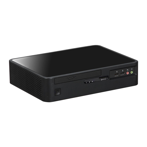
Front and Rear I/O 1. Power Button Press the prower button to turn the system on and off. 2. Slim Type ODD Supports Slim DVD Super-multi Tray type. 3. LED1~3 indicators The LED1can be used to indicate system power sta- tus. - Page 10 8. HDMI Connector Connecting HDMI Device. (Optional) 9. D-SUB Connector Connecting VGA Monitor. 10. DVI Connector The DVI connector allows you to connect a LCD monior. It provice s a high-speed digital interconnec- tion between the computer and its display device. 11.
-
Page 11: Packing Contents
Packing Contents Driver DVD Manual Power Stand NOTE: Please contact us immediately if any of the items is damaged or missing. Introducing the PC... - Page 12 Memo Introducing the PC...
-
Page 13: Installing The Pc
Chapter 2 Installing the PC System Quick Installation 1. Connecting HDMI Device. (Optional) 2. Connecting VGA Monitor. (D-SUB Connector) 3. The USB connectors is for attaching USB devices, such as mouse, keyboard, printer, scanner and other USB-compatible device. Installing the PC... - Page 14 4. Connecting the Network. (LAN Connector) 5. Connecting the Microphone. (Microphone Jack) 6. Connecting Speakers or Headphones. (Headphone Jack) 7. Connecting External Audio Device. (Line In Jack) Installing the PC...
- Page 15 7. Connecting Power. (DC-in jacks) Installing the PC...
-
Page 16: System Components Reinstallation
System Components Reinstallation Installation of Hard Disk Drive 1. Align the screw driver into the screw hole. 2. Use a flat head screw driver to align on the opening. 3. Push the screw driver to release the panel. 4. Raise the panel away from the system. Installing the PC... - Page 17 5. Have the system lie flat on the table. Warning: For safety reason, please ensure that the power cord is disconnected before opening the case. 6. The HDD compartment is shown on the illustration. 7. Use a screw driver to remove the srews attach to the HDD.
- Page 18 10. Locate the two srews and the HDD holder. 11. Insert the holder into the HDD. 12. Align the screw hold on both the HDD and holder. Screw it tightly until it is lock. 13. Align the compartment door into the front of the HDD.
-
Page 19: Installation Of Memory
16. Push to secure the HDD into the compartment. 17. Lock the HDD into its compart- ment with the two screws. Installation of Memory 1. The slot for the RAM module 2. Carefully align the RAM into its slot and press down firmly. Installing the PC... -
Page 20: Installation Of The Stand
Installation of the Stand 1. Locate the stand from the package. 2. Carefully align the stand to the hole on the computer 3. Use a screw to lock up the stand into the computer. Installing the PC... -
Page 21: Using Bios
Chapter 3 Using BIOS About the Setup Utility The computer uses the latest “American Megatrends Inc. ” BIOS with support for Windows Plug and Play. The CMOS chip on the motherboard contains the ROM setup instructions for configuring the motherboard BIOS. The BIOS (Basic Input and Output System) Setup Utility displays the system’s configuration status and provides you with options to set system parameters. -
Page 22: Using Bios
Press the delete key to access the BIOS Setup Utility. CMOS Setup Utility - Copyright (C) 1985-2005, American Megatrends, Inc. Standard CMOS Setup Frequency/Voltage Control Advanced Setup Load Default Settings Advanced Chipset Setup Supervisor Password Integrated Peripherals User Password Power Management Setup Save &... -
Page 23: Standard Cmos Setup
For the purpose of better product maintenance, we reserve the right to change the BIOS items presented in the manual. The BIOS setup screens shown in this chapter are for reference only. Please visit our website for updated manual. Standard CMOS Setup This option displays basic information about your system. - Page 24 Type (Auto) Use this item to configure the type of the IDE device that you specify. If the feature is enabled, it will enhance hard disk performance by reading or writing more data during each transfer. LBA/Large Mode (Auto) Use this item to set the LBA/Large mode to enhance hard disk performance by optimizing the area the hard disk is visited each time.
-
Page 25: Advanced Setup
Advanced Setup This page sets up more advanced information about your system. Handle this page with caution. Any changes can affect the operation of your computer. CMOS Setup Utility - Copyright (C) 1985-2005, American Megatrends, Inc. Advanced Setup Help Item Limit CPUID MaxVal Disabled Intel XD Bit... -
Page 26: Advanced Chipset Setup
Boot Other Device (Yes) When enabled, the system searches all other possible locations for an operating system if it fails to find one in the devices specified under the First, Second and Third boot devices. Press <Esc> to return to the main menu setting page. Advanced Chipset Setup This page sets up more advanced information about your system. -
Page 27: Integrated Peripherals
HDMI Audio (Enabled) This item is used to enable or disable the onboard audio chip. Press <Esc> to return to the main menu setting page. Integrated Peripherals This page sets up some parameters for peripheral devices connected to the system. CMOS Setup Utility - Copyright (C) 1985-2005, American Megatrends, Inc. -
Page 28: Power Management Setup
Power Management Setup This page sets up some parameters for system power management operation. CMOS Setup Utility - Copyright (C) 1985-2005, American Megatrends, Inc. Power Management Setup Help Item ACPI Suspend Type Resume By PCI/PCI-E/Lan PME Disabled Select the ACPI Resume By USB (S3) Disabled state used for... -
Page 29: Pc Health Status
PC Health Status On motherboards support hardware monitoring, this item lets you monitor the parameters for critical voltages, temperatures and fan speeds. CMOS Setup Utility - Copyright (C) 1985-2005, American Megatrends, Inc. PC Health Status Help Item -=- System Hardware Monitor-=- Smart Fan Function Press Enter Shutdown Temperature... -
Page 30: Frequency/Voltage Control
Shutdown Temperature (Disabled) Enable you to set the maximum temperature the system can reach before powering down. System Component Characteristics These items display the monitoring of the overall inboard hardware health events, such as System & CPU temperature, CPU & DIMM voltage, CPU & system fan speed,...etc. -
Page 31: Load Default Settings
PCIE Spread Spectrum (Disabled) This item, when enabled, can significantly reduce the EMI (Electromagnetic Inter- ference) generated by the PCIE. SATA Spread Spectrum (Disabled) This item, when enabled, can significantly reduce the EMI (Electromagnetic Inter- ference) generated by the SATA. PCI Spread Spectrum (Disabled) This item, when enabled, can significantly reduce the EMI (Electromagnetic Inter- ference) generated by the PCI. -
Page 32: User Password
User Password This page helps you install or change a password. CMOS Setup Utility - Copyright (C) 1985-2005, American Megatrends, Inc. User Password User Password : Not Installed Help Item : Move Enter : Select +/-/: Value F10: Save ESC: Exit F1: General Help F9: Load Default Settings User Password (Not Installed) -
Page 33: Using The Software
Chapter 4 Using the Software About the Software DVD-ROM/CD-ROM The support software DVD-ROM/CD-ROM that is included in the motherboard package contains all the drivers and utility programs needed to properly run the bundled products. Below you can find a brief description of each software program, and the location for your motherboard version. -
Page 34: Running Setup
Setup Tab Setup Click the Setup button to run the software installation program. Select from the menu which software you want to install. Browse CD The Browse CD button is the standard Windows command that al- lows you to open Windows Explorer and show the contents of the support disk. - Page 35 Click Next. The following screen appears: Check the box next to the items you want to install. The default options are recom- mended. Click Next run the Installation Wizard. An item installation screen appears: Follow the instructions on the screen to install the items. 1.
-
Page 36: Manual Installation
Manual Installation Insert the disk in the DVD-ROM/CD-ROM drive and locate the PATH.DOC file in the root directory. This file contains the information needed to locate the drivers for your motherboard. Look for the chipset and motherboard model; then browse to the directory and path to begin installing the drivers.
Need help?
Do you have a question about the 3L SFF Nettop MD120 and is the answer not in the manual?
Questions and answers