Table of Contents
Advertisement
Quick Links
Copyright
This publication, including all photographs, illustrations and software, is protected
under international copyright laws, with all rights reserved. Neither this manual, nor
any of the material contained herein, may be reproduced without written consent of
the author.
Version 1.0A
Disclaimer
The information in this document is subject to change without notice. The manufac-
turer makes no representations or warranties with respect to the contents hereof and
specifically disclaims any implied warranties of merchantability or fitness for any
particular purpose. The manufacturer reserves the right to revise this publication and
to make changes from time to time in the content hereof without obligation of the
manufacturer to notify any person of such revision or changes.
Trademark Recognition
®
Windows
VISTA/7 are registered trademarks of Microsoft Corp.
Other product names used in this manual are the properties of their respective
owners and are acknowledged.
FCC
This equipment has been tested and found to comply with the limits for a Class B
digital device, pursuant to Part 15 of the FCC Rules. These limits are designed to
provide reasonable protection against harmful interference in a residential installa-
tion. This equipment generates, uses, and can radiate radio frequency energy and, if
not installed and used in accordance with the instructions, may cause harmful inter-
ference to radio communications. However, there is no guarantee that interference
will not occur in a particular installation. If this equipment does cause harmful
interference to radio or television reception, which can be determined by turning the
equipment off and on, the user is encouraged to try to correct the interference by one
or more of the following measures:
•
Reorient or relocate the receiving antenna
•
Increase the separation between the equipment and the receiver
•
Connect the equipment onto an outlet on a circuit different from that to
which the receiver is connected
•
Consult the dealer or an experienced radio/TV technician for help
Shielded interconnect cables and a shielded AC power cable must be employed with
this equipment to ensure compliance with the pertinent RF emission limits govern-
ing this device. Changes or modifications not expressly approved by the system's
manufacturer could void the user's authority to operate the equipment.
Preface
Preface
Advertisement
Table of Contents
Troubleshooting

Subscribe to Our Youtube Channel
Related Manuals for ECS G11


Summary of Contents for ECS G11
- Page 1 Preface Copyright This publication, including all photographs, illustrations and software, is protected under international copyright laws, with all rights reserved. Neither this manual, nor any of the material contained herein, may be reproduced without written consent of the author. Version 1.0A Disclaimer The information in this document is subject to change without notice.
-
Page 2: Declaration Of Conformity
Declaration of Conformity This device complies with part 15 of the FCC rules. Operation is subject to the following conditions: • This device may not cause harmful interference, and • This device must accept any interference received, including interfer- ence that may cause undesired operation This product has been tested and found to comply with the limits of the European Council Directive on the approximation of the laws of the member states relating to electromagnetic compatibility according to 2004/108/EC. -
Page 3: Safety Instructions
Safety Instructions Your system is designed and tested to meet the latest standards of safety for informa- tion technology equipment. However, to ensure your safety, it is important that you read the following safety instructions. Setting up your system • Read and follow all instructions in the documentation before you oper- ate your system. - Page 4 Safety cautions and warnings Optical Drive Satety Information Optical drive sold with this system contains a CLASS 1 LASER PRODUCT. CAUTION: Invisible laser radiation when open. Do not stare into beam or view directly with optical instructions. WARNING: Makeing adjustments or performing procedures other than those speci- fied in the user’s manual may result in hazardous laser exposuer.
-
Page 5: Table Of Contents
T T T T T ABLE OF CONTENTS ABLE OF CONTENTS ABLE OF CONTENTS ABLE OF CONTENTS ABLE OF CONTENTS Preface Chapter 1 Introducing the PC Introduction..................1 1.1 Specfications................1 1.2 Front view...................2 1.3 Left and right view of the computer........3 1.4 Back view..................5 1.5 Connecting your computer............8 Packing Contents................10... - Page 6 Memo...
-
Page 7: Introducing The Pc
Introducing the PC Introduction Thank you for choosing G11 of great performance and with stylish and flexible design. The G11 will give you an exciting PC experience for it allows you to choose your own favorite motherboard to install. 1.1 Specifications •... -
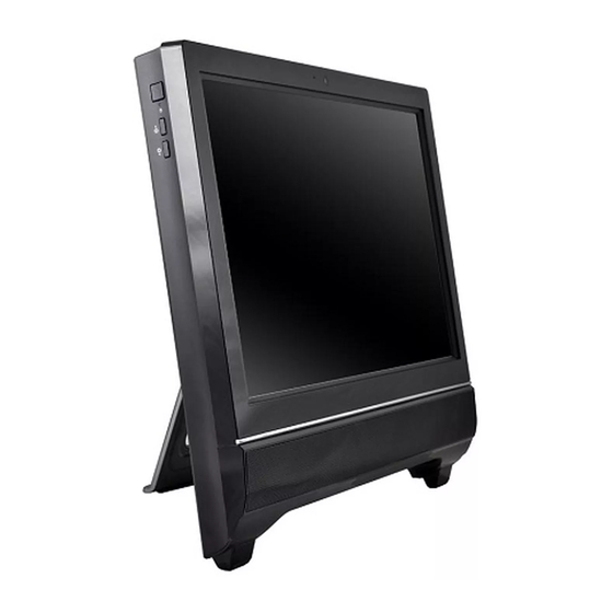
Page 8: Front View
1.2 Front view Note: ID design may vary. Webcam The built-in webcam with the microphone can be used for picture taking, video recoding, online conferencing and any other interactive applications. Built-in Microphone The built-in microphone can be used for video chatting online. LCD/LED Display The 21.5-inch TFT LCD/LED display is with an optimal resolution of 1920X 1080. -
Page 9: Left And Right View Of The Computer
1.3 Left and right view of the computer 1. Power button 2. Brightness up 3. Brightness down 4. Display On/Off (Depend on motherboard support) 1.Power Button Press the power button to turn the system on and off. The blue power LED is when you turn on the system;... - Page 10 5. Optical drive 6. USB ports 7. Headphone Jack 8. MIC Jack 9. Multi Card reader 5.Optical Drive Press the eject button to open the optical disk drive. The ODD LED is on when CD/ DVD is read from or written to the optical disk drive. 6.
-
Page 11: Back View
1.4 Back view Ventilator The ventilator on the enclosure is used for air convection and to prevent the equipment from overheating. Do not cover the ventilator. Attention: Be sure not to block any air vent on the computer. Blocked air vents may cause thermal problems. - Page 12 Computer stand ° ° min. max. Use the stand to position the display to your preference. It can be rotated between 12 and 30 from the vertical. The stand provides stability to the computer; it is not a removable part. Attention: 1.
- Page 13 I/O Inside There are many ports behind the back door, such as USB ports, Lan conn- ector and audio jacks. It mainly depends on the motherboard you choose. Please refer to the specification in Chapter 1. 1. Please remove the back door. 2.
-
Page 14: Connecting Your Computer
1.5 Connecting your computer Use the following information to connect your computer: Look for the small connector icons on the back of your computer. Match the connectors to the icons. Note: Your computer might not have all of the connectors that are described in this section. - Page 15 4. Connect the R45J LAN cable to the LAN port. 5. Your computer is equipped with a Memory Card Reader Connector, it is able to read/write data from: SD/MMC, MS, MS pro, SD Pro. Introducing the PC...
-
Page 16: Packing Contents
Packing Contents Driver DVD Manual Power Cable Quick Guide Adapter Heat Pipe & CPU Fan (Options: depend on motherboard) NOTE: Please contact us immediately if any of the items is damaged or missing. Introducing the PC... -
Page 17: Using Bios
Chapter 2 Using BIOS About the Setup Utility The computer uses the latest “American Megatrends Inc.” BIOS with support for Windows Plug and Play. The CMOS chip on the motherboard contains the ROM setup instructions for configuring the motherboard BIOS. The BIOS (Basic Input and Output System) Setup Utility displays the system’s configuration status and provides you with options to set system parameters. -
Page 18: Resetting The Default Cmos Values
Press the delete key to access BIOS Setup Utility. Aptio Setup Utility - Copyright (C) 2011 American Megatrends, Inc. Main Advanced Chipset Boot Security Save & Exit Set the Date. Use Tab to BIOS Information switch between Data elements. BIOS Version G11_0401 04/01/2011 System Data [ Wed 04/06/2011]... -
Page 19: Bios Navigation Key
In this manual, default values are enclosed in parenthesis. Submenu items are denoted by a triangle The default BIOS setting for this motherboard apply for most conditions with optimum performance. We do not suggest users change the default values in the BIOS setup and take no responsibility to any damage caused by changing the BIOS settings. -
Page 20: Advanced Menu
BIOS Version (G11_0401 04/01/2011) This item shows the information of the BIOS version. Date & Time The Date and Time items show the current date and time on the computer. If you are running a Windows OS, these items are automatically updated whenever you make changes to the Windows Date and Time Properties utility. -
Page 21: Lan Configuration
LAN Configuration The item in the menu shows the LAN-related information that the BIOS automatically detects. Aptio Setup Utility - Copyright (C) 2011 American Megatrends, Inc. Main Advanced Chipset Boot Security Save & Exit Enable/Disable Onboard LAN LAN Configuration Controller Onboard LAN Controller [Enabled] :Select Screen... -
Page 22: Pc Health Status
PC Health Status On motherboards support hardware monitoring, this item lets you monitor the paeameters for critical voltages, temperatures and fan speeds. Aptio Setup Utility - Copyright (C) 2011 American Megatrends, Inc. Main Advanced Chipset Boot Security Save & Exit Smart Fan Function PC Health Status Smart Fan Function... - Page 23 Smart Fan start PWM value (180) This item is used to set the start PWM value of the smart fan. Smart Fan start TEMP(-) (30) This item is used to set the start temperature of the smart fan. DeltaT (+3) This item specifies the range that controls CPU temperature and keeps it from going so high or so low when smart fan works.
-
Page 24: Power Management Setup
Power Management Setup This page sets up some parameters for system power management operation. Aptio Setup Utility - Copyright (C) 2011 American Megatrends, Inc. Main Advanced Chipset Boot Security Save & Exit Power Management Setup About Resume by PCI-E/Lan PME Resume By PCI-E/Lan PME [Disabled] Resume By USB (S3) -
Page 25: Acpi Setting
ACPI Setting The item in the menu shows the highest ACPI sleep state when the system enters suspend. Aptio Setup Utility - Copyright (C) 2011 American Megatrends, Inc. Main Advanced Chipset Boot Security Save & Exit ACPI Settings Select the highest ACPI sleep state the system will enter ACPI Sleep State [S3 (Suspend to RAM)]... - Page 26 Intel(R) Core(TM) i5-2500T CPU @ 2.30GHz This is display-only field and diaplays the information of the CPU installed in your computer. Processor Stepping (206a7) This item shows the processor stepping version. Microcode Revision (d) This item shows the Microcode version. Processor Speed (2300MHz) This item shows the current processor speed.
-
Page 27: Sata Configuration
SATA Configuration Use this item to show the mode of serial SATA configuration options. Aptio Setup Utility - Copyright (C) 2011 American Megatrends, Inc. Main Advanced Chipset Boot Security Save & Exit (1) IDE Mode. (2) AHCI Mode. SATA Configuration SATA Mode [IDE Mode] Serial-ATA Controller 0... -
Page 28: Usb Configuration
USB Configuration Scroll to this item and press <Enter> to view the following screen: Aptio Setup Utility - Copyright (C) 2011 American Megatrends, Inc. Main Advanced Chipset Boot Security Save & Exit USB Configuration Enables Legacy USB support. AUTO option disables legacy support if no USB devices are Legacy USB Support [Enabled]... -
Page 29: Chipset Menu
Chipset Menu The chipset menu items allow you to change the settings for the North chipset, South chipset and other system. Aptio Setup Utility - Copyright (C) 2011 American Megatrends, Inc. Main Advanced Chipset Boot Security Save & Exit North Bridge Parameters North Bridge South Bridge ME Subsystem... - Page 30 South Bridge Scroll to this item and press <Enter> to view the following screen: Aptio Setup Utility - Copyright (C) 2011 American Megatrends, Inc. Main Advanced Chipset Boot Security Save & Exit South Bridge Specify what state to go to when power is re-applied Restore AC Power Loss [Power Off]...
- Page 31 ME Subsystem Scroll to this item and press <Enter> to view the following screen: Aptio Setup Utility - Copyright (C) 2011 American Megatrends, Inc. Main Advanced Chipset Boot Security Save & Exit Intel ME Subsystem Configuration ME Subsystem Help ME Version 7.
-
Page 32: Boot Menu
Boot Menu This page enables you to set the keyboard NumLock state. Aptio Setup Utility - Copyright (C) 2011 American Megatrends, Inc. Main Advanced Chipset Boot Security Save & Exit Enabled/Disabled Quiet Boot Boot Configuration option Quiet Boot [Disabled] Setup Prompt Timeout CSM16 Module Version 07.64 GateA20 Active... -
Page 33: Security Menu
1st/2nd/3rd/4th/5th/6th/7th/8th Boot These items shows the boot priorities. CD/DVD ROM Drive BBS Priorities This item enables you to specify the sequence of loading the operating system from the installing CD/DVD ROM drives. Hard Disk Drive BBS Priorities This item enables you to specify the sequence of loading the operating system from the installing hard disk drives. -
Page 34: Save & Exit Menu
Save & Exit Menu This page enables you to exit system setup after saving or without saving the changes. Aptio Setup Utility - Copyright (C) 2011 American Megatrends, Inc. Main Advanced Chipset Boot Security Save & Exit Exit system setup after saving Save Changes and Exit the changes. - Page 35 SATA/Launch EFI Shell from filesystem device These items set the system boot order. Using BIOS...
-
Page 36: Updating The Bios
Updating the BIOS You can download and install updated BIOS for this motherboard from the manufacturer’s Web site. New BIOS provides support for new peripherals, improve- ments in performance, or fixes for known bugs. Install new BIOS as follows: If your motherboard has a BIOS protection jumper, change the setting to allow BIOS flashing. -
Page 37: Trouble Shooting
Chapter 3 Trouble Shooting Start up problems during assembly After assembling the PC for the first time you may experience some start up problems. Before calling for technical support or returning for warranty, this chapter may help to address some of the common questions using some basic troubleshooting tips. -
Page 38: Troubleshooting Audio Problems
• Change the desktop background • Select a screen saver • Select colors and appearance options for icons and characters • Set resolution and colors by using Display Settings options. Problem: Ripple on screen Troubleshooting and problem resolution: 1. Check for devices located less than one meter from the computer such as refrigerators, electric fans, electric dryers, UPSs, regulators, fluorescent lamps or other computers that may be generating magnetic interference. -
Page 39: Maintenance And Care Tips
Maintenance and care tips Your computer, like any electrical appliance, requires proper care and maintenance. Here are some basic PC care tips to help prolong the life of the motherboard and keep it running as best as it can. 1. Keep your computer in a well ventilated area. Leave some space between the PC and the wall for sufficient airflow. - Page 40 Memo Trouble Shooting...
Need help?
Do you have a question about the G11 and is the answer not in the manual?
Questions and answers