Table of Contents
Advertisement
Quick Links
Copyright
This publication, including all photographs, illustrations and software, is protected under interna-
tional copyright laws, with all rights reserved. Neither this manual, nor any of the material con-
tained herein, may be reproduced without written consent of the author.
Version 2.0
Disclaimer
The information in this document is subject to change without notice. The manufacturer makes no
representations or warranties with respect to the contents hereof and specifically disclaims any
implied warranties of merchantability or fitness for any particular purpose. The manufacturer
reserves the right to revise this publication and to make changes from time to time in the content
hereof without obligation of the manufacturer to notify any person of such revision or changes.
Trademark Recognition
Microsoft, MS-DOS and Windows are registered trademarks of Microsoft Corp. MMX, Pentium,
Pentium-II, Pentium-III, Celeron are registered trademarks of IntelCorporation. Other product names
used in this manual are the properties of their respective owners and are acknowledged.
Regulatory Compliance Information
FCC Declaration of Conformity
This device complies with Part 15 of the FCC Rules. Operation is subject to the following two
conditions:
(1) this device may not cause harmful interference, and (2) this device must accept any interfer-
ence received, including interference that may cause undesired operation.
This equipment has been tested and found to comply with the limits for a Class B digital device,
pursuant to part 15 of the FCC Rules. These limits are designed to provide reasonable protection
against harmful interference in a residential installation. This equipment generates, uses, and
can radiate radio frequency energy and, if not installed and used in accordance with the instruc-
tions, may cause harmful interference to radio communications. However, there is no guarantee
that interference will not occur in a particular installation. If this equipment does cause harmful
interference to radio or television reception, which can be determined by turning the equipment
off and on, the user is encouraged to try to correct the interference by one or more of the following
measures:
Reorient or relocate the receiving antenna.
Increase the separation between the equipment and receiver.
Connect the equipment into an outlet on a circuit different form that to which the receiver is
connected.
Consult the dealer or an experienced radio/TV technician for help.
This equipment complies with FCC radiation exposure limits set forth for an uncontrolled environ-
ment. This equipment should be installed and operated with minimum distance 20 cm between
the radiator and your body.
This device meets the government¡ ¯s requirements for exposure to radio waves.
This device is designed and manufactured not to exceed the emission limits for exposure to radio
frequency (RF) energy set by the Federal Communications Commission of the U.S. Government,
Industry Canada, and other national regulatory agencies.
SKM-U mPC
i
Advertisement
Table of Contents

Subscribe to Our Youtube Channel
Related Manuals for ECS SKM-U


Summary of Contents for ECS SKM-U
-
Page 1: Regulatory Compliance Information
This device meets the government¡ ¯s requirements for exposure to radio waves. This device is designed and manufactured not to exceed the emission limits for exposure to radio frequency (RF) energy set by the Federal Communications Commission of the U.S. Government, Industry Canada, and other national regulatory agencies. SKM-U mPC... - Page 2 Cet équipement doit être installé et utilisé avec un minimum de 20 cm de distance entre la source de rayonnement et votre corps. Taiwan RF: NCC Caution 本產品符合低功率電波輻射性管理辦法 第十二條、第十四條等條文 規定 1. 經型式認證合格之低功率射頻電機,非經許可,公司、商號或使用 者均不得擅自變更頻率、加大功率或變更原 設計之特性及功能。 2. 低功率射頻電機之使用不得影響飛航安全及干擾合法通信; 經發現 有干擾現象時,應立即停用,並改善至無干 擾時方得繼續使用。 前項合法通信,指依電信法規定作業之無線電 通信。 低功率射頻電機須忍受合法通信或工業、 科學及醫療用電波輻射性電機設備之干擾。 SKM-U mPC...
- Page 3 Tominimize pollution and ensure utmost protection of the global environment, please recycle it in European WEEE (waste electrical and electronic equipment) directive system or recycle system in Tai- wan. ® Part NO. Edition 2 Printed in China AUG 2016 SKM-U mPC...
-
Page 4: Packing List
Aucune pièce réparable par l'utilisateur, voir l'entretien à du personnel qualifié. Additional Information and Assistance 1. Visit the ECS websites at www.ECS.com.tw where you can find the latest information about the product. 2. Contact your distributor, sales representative, or ECS’s customer service center for technical support if you need additional assistance. - Page 5 Danger d'explosion si la pile est remplacée de façon incorrecte. Remplacez-la exclusivement par une batterie identique ou par un type de batterie équivalent recommandé par le fabricant La mise au rebut des batteries usagées doit se faire conformément aux indications du fabricant de ces batteries. SKM-U mPC...
-
Page 6: Safety Instructions
VESA mount installation should be performed by a professional technician; please contact the service technician or your retailer if you need this service. 18. Maintenace: to properly maintain and clean the surfaces, use only the approved products or clean with a dry applicator. SKM-U mPC... -
Page 7: Table Of Contents
Figure 2.4 I/O Side View.................6 2.2 Distribution Description....................8 2.3 Powering the System....................8 Chapter 3 Hardware Installation....................9 3.1 Motherboard Introduction...................9 3.2 Installing the Motherboard..................12 Chapter 4 Using BIOS.......................21 4.1 About the Setup Utility....................21 4.2 Using BIOS......................22 Chapter 5 Feature Information....................49 5.1 Introduction......................49 SKM-U mPC... - Page 8 MEMO SKM-U mPC viii...
-
Page 9: Chapter 1 System Information
U SoC for pesonal micro desktop markets or educational usage. Below is a brief summary of the computer’s many features: NOTE: The features listed in this section is for your reference only. The exact configuration of the system depends on the model purchased. SKM-U mPC... -
Page 10: Specifications
1x UAJ(Combo jack) Rear I/O HDMI 1x A type HDMI, support 4K/2K 1x mini DP, support 4K/2K 1x LAN connector, Gigabit LAN USB 3.0 2x USB 3.0 ports 1x DC jack,(base on power consumption) DC Jack 19V 3.43A(65W) 19V 4.74A(90W) SKM-U mPC... - Page 11 NFC header (Optional) (H8x1, 8pins, p=05.mm) HDD LED 1 (SMD, Color.Green) Power button 1 (Design by RD) SYSTEM Windows 10 BIOS 64 Mb SPI ROM Description FSP ADAPTER/FSP065‐10AABA 19Vdc, 3.43A.65W APD ADAPTER/WA‐65B19R Adapter 19Vdc, 3.43A.65W APD ADAPTER/DA‐90F19 19Vdc, 4.74A.90W SKM-U mPC...
-
Page 12: Claeaning/Disinfecting
During normal use SKM-U mPC may become solied and should, therefore, be cleaned regularly. Steps: 1. Wipe SKM-U mPC with a clean cloth that has been moistened in the cleaning solution. 2. Prepare agent per manufacturer’s instructions or hospital protocol. -
Page 13: Chapter 2 Getting Started
Before you start to set up system, take a moment to become familiar with the location sand purposes of the controls, drives, connections and ports, which are illustrated in the figures below. Figure 2.1 Top View Figure 2.2 Bottom View Figure 2.3 Bottom View SKM-U mPC... -
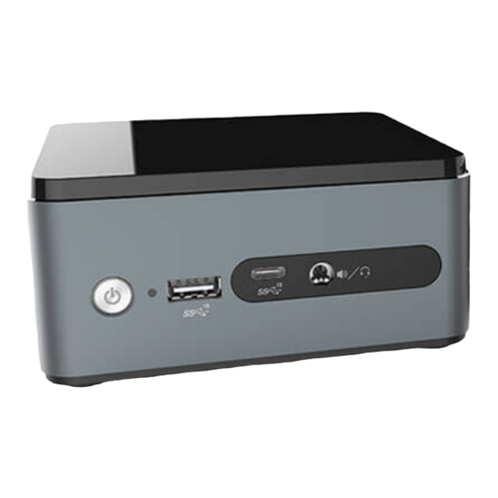
Page 14: Figure 2.4 I/O Side View
Combo Audio Jack (Mic In & Line Out) Wireless Charger / LED (Optional) Kensington Lock Pogo Pin (Optional) DC Jack Speaker (Optional) Thermal Opening HDD LED USB 3.1 (Type C) HDMI IR Sensor RJ45 Port Power Button USB3.0 SKM-U mPC... - Page 15 Install the VESA Mount Extension COM Box (Optional) USB 2.0 COM Port RS422 COM Port RS485 DC Jack DB-44 / RS232 Latch Extension HDD Box (Optional) HDD LENS Micro USB 3.0 Latch SKM-U mPC...
-
Page 16: Distribution Description
Assembly-COM Box / HDD Box COM Box 2.2 Distribution Description The operating system is based on Windows 10 64bit / FreeDOS. 2.3 Distribution Description Connecting a 19V adapter to the DC-In Jack, the system will start up automatically. DC-In SKM-U mPC... -
Page 17: Chapter 3 Hardware Installation
Chapter 3 Hardware Installation 3.1 Motherboard introduction Before you start to set up system, take a moment to become familiar with the location sand purposes of the controls, drives, connections and ports, which are illustrated in the figures below. SKM-U mPC... - Page 18 Logo LED connector 6.SATA_PWR SATA power connector 7.M.2_Wifi M.2 slot for Wifi 8.M.2_SSD M.2 slot for SSD 9.PWR_BTN Power button 10.SATA Serial ATA connector 11.INT_SPK Internal Speaker connector 12.NFC NFC connector 13.SODIMM1~2 DDR4 2133 SO-DIMM slots 14.W_CHARGER Wireless charger connector SKM-U mPC...
- Page 19 Use the combo audio jack to connect the microphone, speaker or headphone. 8. USB 3.1 (Type-C) Port Use the USB 3.1 (Type-C) port to connect USB 3.1 devices. 9. USB 3.1 Port Use the USB 3.1 ports to connect USB 3.1 devices. SKM-U mPC...
-
Page 20: Installing The Motherboard
2. Installing the motherboard in a Chassis • Aim four locating holes of the SKM-U motherboard. • Use four screws to secure the motherboard. Do not over-tighten the screws as this can stress the motherboard. - Page 21 Refer to the following to install the memory modules. Install the DIMM module into the slot and press it firmly down until it fits in place. Check that the cutouts on the DIMM module edge connector match the notches in the DIMM slot. SKM-U mPC...
- Page 22 The M.2 slot is for extending usage which supports half-card with SSD signal. Before installing an add-on card, check the documentation for the card care- fully. If the card is not Plug and Play, you may have to manually configure the card before installation. SKM-U mPC...
- Page 23 Please refer to the following illustrations to install the add-on card: Insert a WIFI card into the M.2_Wifi Slot. * For reference only Insert a SSD card into the M.2_SSD Slot. * For reference only SKM-U mPC...
- Page 24 This section explains how to set jumpers for connecting configuration of the motherboard. 3-4. Connecting Optional Devices. Refer to the following for information on connecting the motherboard’s devices. 1. CPU_FAN: CPU cooling fan connector Connect the CPU cooling fan to the CPU_FAN connector. SKM-U mPC...
- Page 25 2. BAT: Battery connector 2. INT_SPK: Internal Speaker connector SKM-U mPC...
- Page 26 4. W_CHARGER: Wireless charger connector 5. LED_BAR: Logo LED connector SKM-U mPC...
- Page 27 6. SATA: Serial ATA connector 7. SATA_PWR: SATA power connector SKM-U mPC...
- Page 28 8. NFC: NFC connector SKM-U mPC...
-
Page 29: Chapter 4 Using Bios
When you power on the system, BIOS enters the Power-On Self Test (POST) routines. POST is a series of built-in diagnostics performed by the BIOS. After the POST routines are completed, the following message appears: Press DEL to enter SETUP SKM-U mPC... -
Page 30: Using Bios
The default BIOS setting for this motherboard apply for most conditions with optimum performance. We do not suggest users change the default values in the BIOS setup and take no responsibility to any damage caused by changing the BIOS settings. SKM-U mPC... -
Page 31: Bios Navigation Keys
For the purpose of better product maintenance, the manufacture reserves the right to change the BIOS items presented in this manual. The BIOS setup screens shown in this chapter are for reference only and may differ from the actual BIOS. Please visit the manufacture’s website for updated manual. SKM-U mPC... -
Page 32: Main Menu
The Date and Time items show the current date and time on the computer. If you are running a Windows OS, these items are automatically updated whenever you make changes to the Windows Date and Time Properties utility. SKM-U mPC... -
Page 33: Advanced Menu
Trusted Computing : Select Screen : Select Item Enter : Select : Change Opt. : General Help : Previous Values : Optimized Defaults : Save & Exit ESC : Exit Version 2.17.1255. Copyright (C) 2016 American Megatrends, Inc. SKM-U mPC... -
Page 34: Lan Configuration
: Save & Exit ESC : Exit Version 2.17.1255. Copyright (C) 2016 American Megatrends, Inc. Onboard LAN Controller (Enabled) Use this item to enble or disable the Onboard LAN. Press <Esc> to return to the Advanced Menu page. SKM-U mPC... - Page 35 Fan Full Speed Offset (DTS) : Select Screen : Select Item Enter : Select : Change Opt. : General Help : Previous Values : Optimized Defaults : Save & Exit ESC : Exit Version 2.17.1255. Copyright (C) 2016 American Megatrends, Inc. SKM-U mPC...
- Page 36 CPU & DIMM voltage, CPU & System fan speed... etc. • CPU Temperature • System Temperature • CPU Fan Speed • Core Voltage • DIMM Voltage • • +3.3V • +19V Press <Esc> to return to the Advanced Menu page. SKM-U mPC...
- Page 37 You must use an ATX power supply in order to use this feature. EUP Function (Enabled) This item allows user to enable or disable EUP support. Press <Esc> to return to the Advanced Menu page. SKM-U mPC...
- Page 38 Version 2.17.1255. Copyright (C) 2016 American Megatrends, Inc. ACPI Sleep State (S3 (Suspend to RAM)) This item allows you to enter the ACPI S3 (Suspend to RAM) Sleep State (default). Press <Esc> to return to the Advanced Menu page. SKM-U mPC...
- Page 39 This item shows the computer supports Intel VT-x technology or not. Hyper-threading (Enabled) This item only available when the chipset supports Hyper-threading and you are using a Hyper- threading CPU. Active Processor Cores (All) Use this item to control the number of active processor cores. SKM-U mPC...
- Page 40 Package C state limit (AUTO) Use this item to set package C state limit. Enhanced Halt (ClE) (Enabled) Use this item to enable the CPU energy-saving function when the system is not running. Press <Esc> to return to the Advanced Menu page. SKM-U mPC...
- Page 41 This motherboard supports one SATA channel and one M.2_SSD, each channel allows one SATA device to be installed. Use these items to configure each device on the SATA channel and the M.2_SSD. Press <Esc> to return to the Advanced Menu page. SKM-U mPC...
-
Page 42: Usb Configuration
Use this item to enable or disable all USB devices Legacy USB Support (Enabled) Use this item to enable or disable support for legacy USB devices. USB3.1 Contrller (Enabled) Use this item to enable or disable USB3.1 contrller. Press <Esc> to return to the Advanced Menu page. SKM-U mPC... -
Page 43: Super Io Configuration
: General Help : Previous Values : Optimized Defaults : Save & Exit ESC : Exit Version 2.17.1255. Copyright (C) 2016 American Megatrends, Inc. Super IO Chip (IT8607) This item shows the information of the super IO chip. SKM-U mPC... - Page 44 This item shows the information of the device settings. Change Settings (Auto) Use this item to change device settings. Press <Esc> to return to the Super IO Configuration page. Press <Esc> to return to the Advanced Menu page. SKM-U mPC...
- Page 45 This item shows the information of the device settings. Change Settings (Auto) Use this item to change device settings. Press <Esc> to return to the Super IO Configuration page. Press <Esc> to return to the Advanced Menu page. SKM-U mPC...
-
Page 46: Trusted Computing
Use this item to enable or disable the security device. HashPolicy (Sha-1) Select the Hash policy to use. SHA-2 is most secure but might not be supported by all Operating Systems. Press <Esc> to return to the Advanced Menu page. SKM-U mPC... -
Page 47: Chipset Menu
ME Configuration : Select Screen : Select Item Enter : Select : Change Opt. : General Help : Previous Values : Optimized Defaults : Save & Exit ESC : Exit Version 2.17.1255. Copyright (C) 2016 American Megatrends, Inc. SKM-U mPC... -
Page 48: System Agent Configuration
DVMT Memory (256M) When set to Fixed Mode, the graphics driver will reserve a fixed positon of the system memory as graphics memory, according to system and graphics equirements. Press <Esc> to return to the Chipset Menu page. SKM-U mPC... -
Page 49: Pch Configuration
Restore AC Power Loss (Power Off) This item enables your computer to automatically restart or return to its operating status. Azalia HD Audio (Enabled) This item enables or disables Azalia HD audio. Press <Esc> to return to the Chipset Menu page. SKM-U mPC... - Page 50 Version 2.17.1255. Copyright (C) 2016 American Megatrends, Inc. ME Control (Enabled) Use this item to enable or disable the ME Firmware. ME FW Version (9.1.0.1120) This item shows the ME FW version. Press <Esc> to return to the Chipset Menu page. SKM-U mPC...
-
Page 51: Tweak Menu
This is display-only field and displays the information of the CPU installed in your computer. Processor Speed (1800 MHz) This item shows the current CPU speed. Memory Frequency (2133 MHz) This item shows the memory frequency. Total Memory (4096 MB) This item shows the total memory. SKM-U mPC... -
Page 52: Security Menu
Secure Boot Mode (Standard) This item is used to select secure booe mode, when you select standard mode, secure boot policy is fixed; when you select custom mode, the image execution policy and secure boot key datebases are changeable. SKM-U mPC... -
Page 53: Boot Menu
UEFI Hard Disk Drive Priorities This item enables you to specify the sequence of loading the operating system from the installing Hard Disk drive.(This item only shows when there is boot device connecting) Press <Enter> to see the submenu. SKM-U mPC... -
Page 54: Exit Menu
Save as User Defaults This item enables you to save the changes that you have made as user defaults. Restore User Defaults This item enables you to restore the user defaults. Boot Override Use this item to select the boot device. SKM-U mPC... - Page 55 When the installation is complete, remove the bootable device from the computer and restart your computer. If your motherboard has a Flash BIOS jumper, reset the jumper to protect the newly installed BIOS from being overwritten. The computer will restart automatically. SKM-U mPC...
- Page 56 Memo SKM-U mPC...
-
Page 57: Chapter 5 Feature Information
The Wireless charger specification that the computer support is compatible with Qi. Put the Rx device on charger area for power tranfer. 2. NFC The NFC module that compatible with (1) ISO 15693 (2) ISO 14443A (3) ISO 14443B. Put the device on the center of computer for read/write. SKM-U mPC... - Page 58 MEMO SKM-U mPC...
Need help?
Do you have a question about the SKM-U and is the answer not in the manual?
Questions and answers