Table of Contents
Advertisement
Advertisement
Table of Contents

Related Manuals for nifty Heightrider HR21


Summary of Contents for nifty Heightrider HR21
- Page 1 Heightrider Operating & Safety Instructions MODEL HR21 (SP64) HYBRID SERIES Manufactured by: Niftylift Limited Fingle Drive Stonebridge Milton Keynes MK13 0ER England www.niftylift.com e-mail: info@niftylift.com Tel: +44 (0)1908 223456 Fax: +44 (0)1908 312733 M50371/01...
-
Page 3: Table Of Contents
HR Series Operating & Safety Instructions Table of Contents INTRODUCTION AND GENERAL INFORMATION PAGE Foreword Severity of Hazards Scope Introducing the “Height Rider” Self Propelled (SP) Series General Specification Identification EC Declaration of Conformity SAFETY Mandatory Precautions 8-10 Environmental Limitations Noise &... -
Page 4: Introduction And General Information Page
HR Series Operating & Safety Instructions Introduction and General Information FOREWORD The purpose of this manual is to provide the customer with safety, operating and maintenance instructions essential for proper machine operation. This manual should be READ and fully UNDERSTOOD before any attempt is made to operate the machine! Niftylift has no direct control over the machine’s application and use, therefore conformance with good safety practices is the responsibility of the user and operating personnel. -
Page 5: Scope
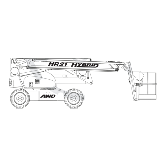
Niftylift Inc, 32 Concourse Way, Greer, SC 29651 USA Tel: +01 864 968 8881 Fax: +01 864 968 8836 Nifty Pty Ltd, 11 Kennington Drive, Tomago, NSW 2322, Australia Tel: +61 (0) 2 4964 9765 Fax: +61 (0) 2 4964 9714 Driven from the platform, the Niftylift Height Rider 21 (SP64) Hybrid is an extremely versatile articulated boom platform of unique and simple design. -
Page 6: General Specification
HR Series Operating & Safety Instructions GENERAL SPECIFICATION FEATURE HR21 (SP64) HYBRID AWD MAXIMUM HEIGHT - WORKING 20.66m 67ft 9in MAXIMUM HEIGHT - PLATFORM 18.70m 61ft 4in MAXIMUM OUTREACH 12.60m 41ft 4in MAXIMUM HEIGHT – STOWED 2.15m MAXIMUM WIDTH 2.25m 7ft 5in MAXIMUM LENGTH –... - Page 7 HR Series Operating & Safety Instructions IDENTIFICATION (UK PLATE) This manufacturer’s plate is attached to the chassis of each machine at the time of manufacture on every Niftylift. Please ensure all sections have been stamped and are legible. English/USA – 11/09 Original Instructions...
-
Page 8: Identification
HR Series Operating & Safety Instructions 1.6a IDENTIFICATION (USA PLATE) This manufacturer’s plate is attached to the base of each machine at the time of manufacture on every Niftylift. Please ensure all sections have been stamped and are legible. English/USA – 11/09 Original Instructions... -
Page 9: Ec Declaration Of Conformity
HR Series Operating & Safety Instructions EC DECLARATION OF CONFORMITY (Typical) EC DECLARATION OF CONFORMITY MANUFACTURER AND NIFTYLIFT LTD PERSON RESPONSIBLE MALCOLM NORTH FOR DOCUMENTATION: ADDRESS: FINGLE DRIVE, MACHINE TYPE: MOBILE ELEVATING WORK PLATFORM MODEL TYPE: SERIAL NUMBER: NOTIFIED BODY: RWTUV Anlagentechnik GmbH NOTIFIED BODY NUMBER: 0044 ADDRESS:... -
Page 10: Safety
HR Series Operating & Safety Instructions Safety MANDATORY PRECAUTIONS When operating your Niftylift, your safety is of utmost concern. In order to fully appreciate all aspects of the machine’s operation it should be ensured that each operator has READ and fully UNDERSTOOD the relevant manual covering machine use, maintenance and servicing. - Page 11 HR Series Operating & Safety Instructions 2.1.10 Never position any part of the Niftylift within 4.0m, (12ft) of any electrical power line, conductor or similar not exceeding 66kV. (Minimum span 125m) Other distances for increased voltages and different spans are given in NZECP 34:1993. THIS MACHINE IS NOT INSULATED.
- Page 12 HR Series Operating & Safety Instructions 2.1.23 It shall be the responsibility of the user to determine the hazard classification of any particular atmosphere or location. Aerial platforms operated in hazardous locations shall be approved and suitable for the duty. (See ANSI/NFPA 505-1987 where applicable). 2.1.24 The operator shall immediately report to his supervisor any potentially hazardous location(s) (environment) which become evident during operation.
-
Page 13: Environmental Limitations
HR Series Operating & Safety Instructions 2.1.37 The operator shall implement means provided to protect against use by unauthorised persons. 2.1.38 Never remove anything that may affect the stability of the machine such as, but not limited to, batteries, covers, engines, tyres or ballast. ENVIRONMENTAL LIMITATIONS Unless specifically configured otherwise, the machine will have a short operational time in extreme temperatures such as freezers and cold storage, due to reduced battery performance. -
Page 14: Test Report
HR Series Operating & Safety Instructions TEST REPORT All Niftylift machine models are subjected to a comprehensive ‘type test’ which duplicates all combinations of safe working load (SWL), overload, windage, inertia and pull force to assess the various safe stability criteria. Self propelled machines are also subjected to kerb and braking tests at the SWL to satisfy additional ‘worse case’... -
Page 15: Preparation And Inspection
HR Series Operating & Safety Instructions Preparation and Inspection UNPACKING Since the manufacturer has no direct control over the shipping or carriage of any Niftylift it is the responsibility of the dealer and/or owner and/or lessee to ensure the Niftylift has not been damaged in transit and a Pre-operational Report has been carried out by a qualified engineer before the aerial platform is put into service. -
Page 16: Pre-Operational Safety Check Schedules
HR Series Operating & Safety Instructions PRE-OPERATIONAL SAFETY CHECK SCHEDULES Before use each day and at the beginning of each shift the aerial platform shall be given a visual inspection and functional test including, but not limited to, the following: 3.3.1 DAILY SAFETY CHECKS Check that all labels (decals) are in place and legible. - Page 17 HR Series Operating & Safety Instructions 3.3.3 MONTHLY SAFETY CHECKS Check the engine oil level (if applicable). Check the wheel nuts (torque 110ft lbs / 150Nm). Check that the bolts holding the wheel motors to the chassis are secure. Check that the slew worm is secured and correctly in mesh. Clean and re-grease. Inspect brakes for operation and wear.
- Page 18 HR Series Operating & Safety Instructions SPAIN, GREECE, TURKEY, CHINA, USA (MID WEST STATES), AUSTRALIA (TASMANIA) 9.5 years MALAYSIA, INDONESIA 8 years USA (SOUTH STATES), SOUTH AMERICA, AUSTRALIA (VICTORIA, NEW SOUTH WALES) 7.5 years USA (WEST STATES), SOUTH AFRICA, INDIA, PAKISTAN, IRAN, AUSTRALIA (WESTERN, 7 years SOUTH, QUEENSLAND) NORTH AFRICA, SAUDI, DUBAI, AUSTRALIA (NORTHERN TERRITORY)
-
Page 19: Placard, Decals And Installation
HR Series Operating & Safety Instructions PLACARD, DECALS & INSTALLATION (UK SPEC) ITEM DESCRIPTION NUMBER “Niftylift.com” P14390 Harness Point P14883 Head Protection P14921 Danger HR & TM’s P21970 “If E-Stop Disabled P14864 Hydraulic Oil P14415 SWL 225kg P17328 Manual Hand Pump P19605 Daily Safety Check List P14908... - Page 20 HR Series Operating & Safety Instructions English/USA – 11/09 Original Instructions...
-
Page 21: Placard, Decals And Installation
HR Series Operating & Safety Instructions 3.4a PLACARD, DECALS & INSTALLATION (USA SPEC) ITEM DESCRIPTION NUMBER “Niftylift.com” P14390 Harness Point P14883 Head Protection P14921 Danger HR & TM’s P21970 “If E-Stop Disabled P14864 Hydraulic Oil P14415 SWL 500 lbs P17328 Manual Hand Pump P19605 Daily Safety Check List... - Page 22 HR Series Operating & Safety Instructions English/USA – 11/09 Original Instructions...
-
Page 23: Torque Requirements
HR Series Operating & Safety Instructions TORQUE REQUIREMENTS SCREW QUALITY/SIZE Tightening torque in ft lbs (Nm) Grade 10.9 (10) (14) (25) (35) M 10 (49) (69) M 12 (86) (120) M 14 (135) (190) M 16 (210) (295) M 18 (290) (405) WHEEL NUTS... -
Page 24: Operation
HR Series Operating & Safety Instructions Operation CONTROL CIRCUIT COMPONENTS 4.1.1 MAIN CONTROL BOARD: - Situated under the left-hand superstructure cover, the encapsulated control board comprises a PCB (printed circuit board) design which incorporates all of the relays to control the machine operation. - Page 25 HR Series Operating & Safety Instructions 4.1.7 BOOM-SWITCHES: - Mounted on the tele-knuckle and links knuckle, and operated by any of the booms raising and/or the telescopic boom extending, these switches control both the operation of the Tilt Alarm Sensor, and the speed control function. With the booms in the stowed position, the Tilt Alarm Sensor is by-passed, allowing the machine to negotiate slopes in excess of the permissible working angle, without isolating the drive function.
- Page 26 HR Series Operating & Safety Instructions 4.1.11 DIESEL ENGINE: - A Kubota 722 engine described in the maintenance section of the Workshop Manual, driving a swash plate pump with integral relief valve on the main control valve. This arrangement allows two speed operation of all functions. 4.1.12 HOUR METER: - Monitors and displays time of diesel engine usage (Located on base control box).
-
Page 27: Ground Control Operation
HR Series Operating & Safety Instructions GROUND CONTROL OPERATION 4.2.1 GROUND CONTROL FUNCTIONS P21750/01 1 Emergency Stop Push to Stop machine Turn clockwise to Release 2 Diesel Glow/Start Selector Anti-clockwise for Glow, Clockwise to Start engine 3 Cage Overload Indicator Flashing red 4 Base/Platform Selector Up for Platform, Down for Base, 0 for all power off... - Page 28 HR Series Operating & Safety Instructions 4.2.2 OPERATION ALWAYS ALLOW THE ENGINE TO WARM UP BEFORE OPERATING. ALL MODELS Ensure all red emergency stops are out. Turn Base/Platform selector at ground control station to Ground (Clockwise). For Battery powered operation, go to step 7). For Diesel powered operation, go to step 5).
-
Page 29: Platform Control Operation
HR Series Operating & Safety Instructions PLATFORM CONTROL OPERATION 4.3.1 PLATFORM CONTROL FUNCTIONS P20663/03 1 Digital Gauge See diagram on page 27 Indicates Safety Critical Problem 2 Safety Warning Lamp (Refer to Digital Gauge immediately) 3 Cage overload indicator Constant or Flashing amber (Refer to Section 4.6) 4 Cage overload indicator Constant green (Refer to Section 4.6) 5 On/Off Switch... - Page 30 HR Series Operating & Safety Instructions MULTI-FUNCTION DIGITAL GAUGE Situated on the Cage Control Panel, this gauge provides a warning indication for a range of functions. The red warning lamps on the right hand side indicate a safety critical situation where immediate action is required;...
- Page 31 HR Series Operating & Safety Instructions 4.3.2 OPERATION NEVER START THE NIFTYLIFT IF YOU SMELL PETROL (GASOLINE), LIQUID PROPANE OR DIESEL. THESE FUELS ARE FLAMMABLE. BEFORE OPERATING THE NIFTYLIFT ENSURE THAT EACH OPERATOR HAS READ AND FULLY UNDERSTOOD THE OPERATING MANUAL. FAILURE TO DO SO MAY RESULT IN DEATH OR SERIOUS INJURY.
- Page 32 HR Series Operating & Safety Instructions 4.3.3 SiOPS - LOAD SENSING CONSOLE (If fitted) WHEN OPERATING THIS MACHINE THE USER MUST BE AWARE OF ANY OVERHEAD OBSTRUCTIONS. This machine incorporates a load sensing cage console that senses if the operator has been pushed or has fallen against the console.
-
Page 33: Driving Controls
HR Series Operating & Safety Instructions DRIVING CONTROLS DO NOT OPERATE THE NIFTYLIFT WHILST ELEVATED UNLESS ON A FIRM, LEVEL SURFACE FREE FROM ANY POSSIBLE OBSTRUCTIONS OR HAZARDS BOTH AT GROUND LEVEL AND OVERHEAD. Check proposed route for possible hazards, obstructions and personnel. Depress switch located on the front of the joystick. - Page 34 HR Series Operating & Safety Instructions ALL NIFTYLIFTS ARE FITTED WITH A TILT ALARM - PRE-SET IN THE FACTORY. ONCE ENERGISED THE NIFTYLIFT WILL LOSE ALL POWER TO DRIVE FUNCTIONS AND A LOUD AUDIBLE ALARM WILL BE ACTIVATED. TO DE-ACTIVATE, LOWER THE BOOMS FULLY TO STOWED POSITION AND RE-POSITION BASE ON FIRM, LEVEL GROUND.
-
Page 35: Cage Weigh System
HR Series Operating & Safety Instructions CAGE WEIGH SYSTEM 4.5.1 LOAD CELL VERSION The Niftylift HR21 Hybrid is fitted with an electronic load cell. This load cell is a moment-independent, redundant design. This means that independent of the load position inside the cage of the machine, the actual load is measured and if pre-configured limit values are exceeded, warnings will be activated. -
Page 36: Batteries And Charging
HR Series Operating & Safety Instructions BATTERIES AND CHARGING BATTERIES MUST BE RECHARGED IN A WELL-VENTILATED AREA FREE OF FLAME, SPARKS OR OTHER HAZARDS THAT MAY CAUSE EXPLOSION. HIGHLY EXPLOSIVE HYDROGEN GAS IS PRODUCED DURING THE CHARGING PROCESS. Recharge batteries at the end of every working day or shift. (Note: To recharge batteries fully from flat takes approx. - Page 37 HR Series Operating & Safety Instructions Notes: If the charger is reconnected to the power supply shortly after it has gone through its full charging cycle, the charger will show an Amber light, immediately followed by the Green 80% lamp. The charger would then go through its complete cycle again at an accelerated rate, depending on the time difference between connection, reconnection and level of battery charge.
- Page 38 HR Series Operating & Safety Instructions The charger requires a minimum battery voltage of 4.5 volts per battery (overall for two batteries 9 volts, for 4 batteries 19 volts for 8 batteries 38 volts). If the voltage is below these values then the charger will not function (Charger will not detect batteries to begin charge.) If the batteries have fallen to such a poor state they will have to be removed from the machine and charged individually with an independent charger until the optimum voltage has been reached.
-
Page 39: Transporting, Craneage, Storage And Setting To Work
HR Series Operating & Safety Instructions TRANSPORTING, CRANEAGE, STORAGE AND SETTING TO WORK 4.7.1 TRANSPORTING The following guidelines should be adhered to ensuring safe transportation of the work platform. Cross loading between transport locations is the most frequent cause of problems, as the method of loading is no longer in sight of our own personnel. - Page 40 HR Series Operating & Safety Instructions 4.7.2 CRANEAGE Observe all of the limitations relating to straps and chains stated above under ‘Transporting’. (4.7.1) When utilising the designated lifting points never apply a ‘snatch’ load, i.e. lift slowly to take up the load before raising.
- Page 41 HR Series Operating & Safety Instructions On completion of an extended period of road transport, the machine might need additional inspection to identify any transit degradation, which could render the machine unsafe. Perform a P.D.I. inspection on the unit before it enters service. Record any faults found and rectify them immediately.
-
Page 42: Emergency Controls
HR Series Operating & Safety Instructions Emergency Controls GENERAL CHECKING THE OPERATION OF THE EMERGENCY CONTROLS EVERY DAY AND/OR BEFORE EACH SHIFT IS AN ESSENTIAL PART OF THE OPERATOR'S DUTIES The operator and all ground personnel must be thoroughly familiar with the location and operation of the EMERGENCY CONTROLS. -
Page 43: Boom Controls
HR Series Operating & Safety Instructions BOOM CONTROLS On opening the canopy cover, the hand pump handle is revealed. Remove the handle and fit it to the hand pump as shown. When the handle is actuated, hydraulic flow is generated and will be supplied directly to the ground control valve block. -
Page 44: Towing
HR Series Operating & Safety Instructions TOWING Towing the Niftylift in case of an emergency. If necessary, chock the wheels before carrying out any of the following actions. 5.5.1 GEARBOX DISENGAGEMENT In order to safely tow the HR21 Hybrid, the drive mechanism and parking brakes will need to be bypassed. -
Page 45: Incident Notification
HR Series Operating & Safety Instructions INCIDENT NOTIFICATION It is a mandatory requirement that any accident or incident involving a Niftylift, regardless of whether any party received injury or property was damaged is reported by telephone directly to Niftylift. Failure to do so may render any warranty on the machine void. -
Page 46: Inspection/ Service Check List
HR Series Operating & Safety Instructions Inspection/Service/Pre-Hire Check list MACHINE SERIAL NO TOWING PASS FAIL Machine secured on trailer Straps correctly positioned and tightened Wheels chocked if necessary AXLES, WHEELS AND BRAKES Wheels are secure, tyre condition acceptable Wheel bearings O.K. Brake linkages and cables secure Brake shoe wear not excessive Machine climbs slope... - Page 47 HR Series Operating & Safety Instructions TILT ALARM PASS FAIL Booms raised on slope - drive disabled, siren tone constant Boom operation unaffected Booms lowered - drive restored INTERNAL (POWER PACK) Power pack and all components secure All cables and terminals secure All hose connections secure Hoses not kinked or fouled Charger/control box secure...
Need help?
Do you have a question about the Heightrider HR21 and is the answer not in the manual?
Questions and answers
To charge batteries on nifty lift 50 what do I do besides plugging cable into 120 v socket
To charge the batteries on a Nifty HR21 lift besides using a 120V socket, you can also plug the charger into a suitable 240V AC power supply. When using 240V, it is recommended to use a properly rated Earth Leakage Circuit Breaker (ELCB) or Residual Current Device (RCD) at the power source.
This answer is automatically generated