Table of Contents
Advertisement
Quick Links
Advertisement
Table of Contents

Related Manuals for YOKOGAWA CA150


Summary of Contents for YOKOGAWA CA150
- Page 1 User's CA150 HANDY CAL Manual IM CA150E IM CA150E 2nd Edition: Apr. 2007...
-
Page 2: Introduction
Introduction Thank you for purchasing the CA150 HANDY CAL. This User’s manual contains useful information regarding the instrument's functions and operating procedures, as well as precautions that should be observed during use. To ensure proper use of the instrument, read the manual thoroughly before operating it. -
Page 3: Checking The Contents Of The Package
Check that the model name given on the name plate on the back panel of the instrument matches the one on your order. • Model Model CA150 • Serial No. Should you need to contact the dealer from whom you purchased the instrument, have your unit's serial number handy to give to the person. -
Page 4: Optional Accessories
Checking the Contents of the Package Optional Accessories The following optional accessories are available. Upon receiving these optional accessories, make sure that all the items you ordered have been supplied and are undamaged. If you have any questions regarding optional accessories, or if you wish to place an order, contact the dealer from whom you purchased the instrument. -
Page 5: Safety Precautions
When operating the instrument, strictly observe the precautions in this manual to ensure its correct and safe operation. If used other than as instructed in this manual, Yokogawa Meters & Instruments Corporation is not liable for any damage that may result. - Page 6 Some parts inside the instrument are extremely dangerous because they use a high voltage. When the instrument needs an internal inspection or calibration, contact Yokogawa Meters & Instruments Corporation or the dealer from whom you purchased the instrument. To use the AC adapter (optional) safely, be sure to comply with the following precautions.
-
Page 7: Table Of Contents
Contents Introduction ..................1 Checking the Contents of the Package ........2 Safety Precautions ................4 1. Product Outline ............1-1 Product Outline ..............1-1 2. Names and Functions of Parts ....... 2-1 3. Before Starting Source or Measurement ....3-1 Usage Precautions ............. 3-1 Connecting a Power Supply .......... - Page 8 Contents Source Frequency and Pulse (PULSE) Signals ..... 4-15 4.7.1 Source a Continuous Pulse Train ......4-16 4.7.2 Source a Pulse Cycle ..........4-17 Divided Output (n/m) Function ........4-18 Sweep Output Functions ..........4-19 4.9.1 Step Sweep Function ..........4-20 4.9.2 Linear Sweep Function ..........
- Page 9 Contents 8. Communication Function ........8-1 Cable Connection and Interface Specifications ....8-1 Communication Command List ........8-2 Detailed Description of Commands ......... 8-3 Error Code List ..............8-12 Table of Valid Communication Commands ....8-13 Status Byte Format ............8-15 Output Format of Printer Mode ........
-
Page 10: Product Outline
Product Outline 1.1 Product Outline Generation (SOURCE) Function Range DC Voltage (DCV) 100 mV, 1 V, 10 V, 30 V DC Current (DCA) 20 mA, 20 mA SINK, 4-20 mA Resistance ( ) , 5 k , 50 k Thermocouple (TC) K, E, J, T, N, L, U, R, S, B Resistance temperature detector (RTD) Pt100, JPt100 Frequency and pulse (PULSE) -
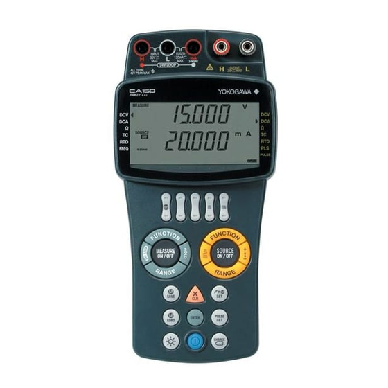
Page 11: Names And Functions Of Parts
Names and Functions of Parts Input terminals Output terminals Fuse holder (FUSE) LCD Screen Output value setting keys Measure Source keys keys Keys Battery holder RJ sensor connector RS232 connector AC adapter jack IM CA150E... - Page 12 Common Keys POWER Turns on/off the power. LIGHT Turns on/off the backlight of the LCD screen. (It turns off automatically if approximately 10 minutes elapse without a key being pressed.) SAVE Saves measurement values and setting values. LOAD Displays measurement values and loads setting values. ENTER Confirms the selected item or displays the temperature monitor.
- Page 13 SOURCE Keys Changes the source function. DCV → DCA → FUNCTION → TC → RTD → PULSE → (DCV) (The mark is lit for the selected function.) RANGE Changes the range for each function. SOURCE ON/OFF Turns on/off the source (setting value output). Selects/cancels divided output (n/m) mode.
- Page 14 LCD Screen Indicates the function selected with the FUNCTION key of MEASURE. Indicates the measurement value (top row: seven segments). MEASURE and the unit are also displayed. Indicates the function selected with the FUNCTION key of SOURCE. Indicates the source setting value (bottom row: seven segments). SOURCE and the unit are also displayed.
- Page 15 SOURCE: OFF lights when output is off or the protection circuit has been activated. ON lights when output is on. Indicates hold. Indicates that the 4-20 mA range is selected for the source. Flashes while communication data is being output. (When communication of the setting mode is set to printer mode.) Indicates that 24 V DC is being output for a loop test.
- Page 16 Digital Display of Alphanumeric Characters Since the LCD screen of the instrument has seven segments, alphanumeric characters are displayed as shown below. (Some of the characters are not used.) IM CA150E...
-
Page 17: Before Starting Source Or Measurement
Some parts inside the instrument are extremely dangerous because they use a high voltage. When the instrument needs an internal inspection or calibration, contact Yokogawa Meters & Instruments Corporation or the dealer from whom you purchased the instrument. In the case of an abnormality If the instrument begins to emit smoke, give off an unusual odor, or show any other signs of an abnormality, immediately turn off the power switch. - Page 18 Chapter 3.1 Usage Precautions Operating Environment Use the instrument in locations that meet the following conditions: • Ambient temperature and humidity Ambient temperature: 0 to 40 C Ambient humidity: 20 to 80% RH (no condensation) Do not use the instrument in the following locations: •...
-
Page 19: Connecting A Power Supply
Chapter 3.2 Connecting a Power Supply 3.2 Connecting a Power Supply In addition to AA-size alkaline batteries (six), the instrument can use two other types of power supply. • AA-size (LR6) alkaline batteries (six): 1.5 V • AC adapter (optional) •... -
Page 20: Using An Ac Adapter
Chapter 3.2 Connecting a Power Supply 3.2.2 Using an AC Adapter Warning • Use the power cord supplied by Yokogawa Meters & Instruments Corporation for use with the instrument. • Make sure that the power supply voltage matches the ratedsupply voltage before connecting the power cord. -
Page 21: Using An Nimh Battery Pack
AC adapter power cord from the outlet to avoid possible danger such as a short in the electric circuit or electrical shock. • Do not use any battery pack other than Yokogawa Meters and Instruments Corporation's NiMH battery pack (model: 94015). - Page 22 Chapter 3.2 Connecting a Power Supply Installing the NiMH Battery Make sure that the power switch of the instrument is turned off and the lead cables and AC adapter are not connected. If alkaline batteries are in use, slide up the lock switch on the left side of the instrument and remove the alkaline battery holder before installing the NiMH battery.
- Page 23 AC adapter for charging. Warning Be sure to use the CA150 to charge the NiMH battery. Charge the NiMH battery in an environment with a temperature within the range of 10 to 35 C. Charging the battery at a temperature that is not in the range above may result in an insufficient charge, solution leakage, or heating up.
-
Page 24: Fuse
Chapter 3.2 Connecting a Power Supply NiMH Battery Life The battery can be charged approximately 300 times. (This number varies depending on the operating environment.) The life of the battery is over when the low battery level indication appears only a short time after the battery is fully charged. -
Page 25: Turning The Power On And Off
Chapter 3.3 Turning the Power On and Off 3.3 Turning the Power On and Off 3.3.1 Turning the Power On and Off When the power is off, press the POWER key to turn the power on. Press the POWER key again to turn the power off. Note Turn the power off before disconnecting the AC adapter from the power supply. -
Page 26: Operating Environment
2000 m max. above sea level. Location Indoors Measurement Category (CAT.) The measurement category of the CA150 is I. Warning Do not use the CA150 for measurements in locations falling under Measure- ment Categories II, III, and IV. Measurement Category Measurement Category Description Remarks CAT. - Page 27 Note • For accurate source and measurement, operate the CA150 in the 23 ± 5 C tem- perature range and 55 ± 10% RH. • Condensation may occur if the CA150 is moved to another place where the ambient temperature and humidity are higher, or if the temperature changes rapidly.
-
Page 28: Source
Source The instrument can source DC voltage, DC current (current sink), resistance, thermocouple, resistance temperature detector, and frequency/pulse signals. Warning To protect against the risk of electrical shock, do not apply a voltage of 30 V or more to the output terminals. Also ensure that the circuit-to-ground voltage does not exceed 30V. -
Page 29: Connecting The Source Terminals
4.1 Connecting the Source Terminals 4.1 Connecting the Source Terminals Connect the supplied source lead cables (model: 98020) to the output terminals of the instrument. Connect the clips to the input terminals of the target device. Be sure to confirm the polarity to ensure the clips are correctly connected to the input terminals. -
Page 30: Source Dc Voltage (Dcv) Signals
4.2 Source DC Voltage (DCV) Signals 4.2 Source DC Voltage (DCV) Signals Connect the terminals. Use the FUNCTION key on the SOURCE side to align the source mark with DCV. (DC voltage selection) Use the RANGE key to select a range. (100 mV, 1 V, 10 V, or 30 V) Use the output value setting keys to set each digit output value. -
Page 31: Source Dc Current (Dca) Signals
4.3 Source DC Current (DCA) Signals 4.3 Source DC Current (DCA) Signals 4.3.1 Source DC Current Signals Connect the terminals. Use the FUNCTION key on the SOURCE side to align the source mark with DCA. (DC current selection) Use the RANGE key to select the 20 mA range. (Max. 22.000 mA) Use the output value setting keys to set each digit output value. -
Page 32: Ma Function
4.3 Source DC Current (DCA) Signals 4.3.2 4-20 mA Function The source current can be increased or decreased in 4 mA steps. 4 mA steps Connect the terminals. Use the FUNCTION key on the SOURCE side to align the source mark with DCA. -
Page 33: Ma Sink Function
H L mA MEASURE SOURCE AC or DC power supply CA150 Use the FUNCTION key on the SOURCE side to align the source mark with DCA. (DC current selection) Use the RANGE key to select the 20 mA range. (-22.000 mA to 22.000 Use the output value setting keys to set each digit output value. - Page 34 MEASURE SOURCE CA150 • If the equipment's input inductance component is too large, connect a 200- resistor R and a 1- F capacitor C to the instrument's outputs, as shown in the figure below. This setup makes it possible to connect an input having an inductance component of up to 3 H to the instrument.
-
Page 35: Source Resistance ( ) Signals
0.01 F, the instrument may be unable to generate correct resistance values. Three-wire Connection Output Method Attach another black source lead cable (98020) to the output terminal L side. Black Device under calibration (Three-wire measuring equipment) SOURCE CA150 IM CA150E... - Page 36 4.4 Source Resistance ( ) Signals Connect the terminals. Use the FUNCTION key on the SOURCE side to align the source mark with . (Resistance selection) Use the RANGE key to select a range. (500 , 5 k , or 50 k ) Use the output value setting keys to set each digit output value.
-
Page 37: Source Thermocouple (Tc) Signals
4.5 Source Thermocouple (TC) Signals 4.5 Source Thermocouple (TC) Signals 4.5.1 Source Thermocouple (TC) Signals Generate voltages (mV) corresponding to the following thermocouples. Set the temperature with ( C). This enables calibration of a thermometer. Thermocouple (TC) types: K, E, J, T, N, L, U, R, S, B (For the temperature range, refer to the specifications.) Connect the terminals. -
Page 38: Using An External Rj Sensor
(generates) the compensated value. When calibrating a device with a built-in reference junction temperature compensator, connect an optional RJ sensor (model: B9108WA) to the instrument (RJ sensor connector). (RJON appears.) CA150 unit RJ sensor (B9108WA) Device under Device under calibration... -
Page 39: Using The Built-In Rj Sensor
4.5 Source Thermocouple (TC) Signals 4.5.3 Using the Built-in RJ Sensor Although accurate temperature output (reference junction compensation) requires an external RJ sensor to be used, you can use the RJ sensor built into the instrument. The default setting (at shipment) is OFF. Set the built-in RJ sensor to ON (enable) in setting mode. -
Page 40: Source Resistance Temperature Detector (Rtd) Signals
4.6 Source Resistance Temperature Detector (RTD) Signals 4.6 Source Resistance Temperature Detector (RTD) Signals Resistance Temperature Detector: Select from PT100 and JPT100. Temperature scale standard: Select from ITS-90 and IPTS-68. (The default setting: ITS-90) The temperature scale standard can be set in setting mode. Connect the terminals. - Page 41 4.6 Source Resistance Temperature Detector (RTD) Signals Setting the Temperature Scale Standard You can select from ITS-90 and IPTS-68 in setting mode. (The default setting: ITS-90) ITS-90: 1990 International Temperature Scale IPTS-68: 1968 International Practical Temperature Scale ENTER ENTER Simultaneously press the CLEAR and ENTER keys to switch to setting mode.
-
Page 42: Source Frequency And Pulse (Pulse) Signals
4.7 Source Frequency and Pulse (PULSE) Signals 4.7 Source Frequency and Pulse (PULSE) Signals Amplitude voltage Frequency (setting value) (continuous) SOURCE Frequency (setting value) Amplitude voltage Pulse cycle (setting value) SOURCE n = pulse number Frequency (setting value) (setting value) PULSE SET Key When the generation of frequency and pulse signals is selected with FUNCTION of SOURCE, each press of the PULSE SET key toggles the mode... -
Page 43: Source A Continuous Pulse Train
4.7 Source Frequency and Pulse (PULSE) Signals 4.7.1 Source a Continuous Pulse Train Connect the terminals. Use the FUNCTION key on the SOURCE side to select frequency and pulse (PULSE). ( PULSE appears.) Use the RANGE key to select a frequency setting mode. (Default setting: 100 Hz) (100 Hz, 1000 Hz, 10 kHz, 50 kHz, 1000 CPM) Use the... -
Page 44: Source A Pulse Cycle
4.7 Source Frequency and Pulse (PULSE) Signals 4.7.2 Source a Pulse Cycle Connect the terminals. Use the FUNCTION key on the SOURCE side to select frequency and pulse (PULSE). ( PULSE appears.) Use the RANGE key to select a frequency setting mode. (Default setting: 100 Hz) (100 Hz, 1000 Hz, 10 kHz, 50 kHz, 1000 CPM) Use the... -
Page 45: Divided Output (N/M) Function
4.8 Divided Output (n/m) Function 4.8 Divided Output (n/m) Function The divided output (n/m) function outputs a value n/m times the setpoint of a voltage, current, resistance, thermocouple or resistance temperature detector (RTD) signal. Output value = setting value n/m. Setting value n/m key Set the source value to output (FUNCTION, RANGE, Setting Value). -
Page 46: Sweep Output Functions
4.9 Sweep Output Functions 4.9 Sweep Output Functions Three types of sweep output (generation) are available. Each press of the (SWEEP SET) key toggles the mode as shown below. Step Sweep → Linear Sweep → Program Sweep → Cancel When frequency or pulse (PULSE) is selected using FUNCTION, the sweep functions (step, linear, and program) cannot be used. -
Page 47: Step Sweep Function
4.9 Sweep Output Functions 4.9.1 Step Sweep Function Set divided output (n/m) to be generated automatically as shown in the figure below. Source value indication Setting value Actual output Interval time setting value SOURCE ON key operation Press (ON) Set the source value to output (FUNCTION, RANGE, Setting Value). Press the SWEEP SET key to select Step Sweep. - Page 48 4.9 Sweep Output Functions Sweep Interval Time You can change the sweep interval time. The default setting (at shipment) is 5 seconds (FAST). Set 5 seconds (FAST) or 10 seconds (SLOW) in setting mode. When a sweep function is enabled, a setting mode cannot be selected. Disable the sweep function by pressing the SWEEP SET key and switch to the normal mode.
-
Page 49: Linear Sweep Function
4.9 Sweep Output Functions 4.9.2 Linear Sweep Function Output can be varied in a continuous manner as shown in the figure below. SOURCE ON indication SOURCE OFF indication Flashing Flashing Setting value Source value indication Actual output Approx. 2 sec Approx. - Page 50 4.9 Sweep Output Functions Linear Sweep Time You can change the linear sweep time. The default setting (at shipment) is 16 seconds (FAST). Set 16 seconds (FAST) or 32 seconds (SLOW) in setting mode. When a sweep function is enabled, a setting mode cannot be selected. Disable the sweep function by pressing the SWEEP SET key and switch to the normal mode.
-
Page 51: Program Sweep Function
4.9 Sweep Output Functions 4.9.3 Program Sweep Function Multiple setting values saved with the SAVE key can be output in order as shown in the figure below. Source Value Memory Number Function Range (Setting Value) 10 V 5.0000V 10 V 1.0000V 10 V 4.0000V... - Page 52 4.9 Sweep Output Functions Saving Source Values Set the source value to output (FUNCTION, RANGE, Setting Value). Press the SAVE key. (MEM No. appears.) Use the key to select the memory number. Press the ENTER key to confirm the selection. (MEM No. disappears.) Source value Program Sweep Press the SWEEP SET key three times to select Program Sweep.
-
Page 53: Temperature Monitor Function
4.10 Temperature Monitor Function 4.10 Temperature Monitor Function The ambient temperature (temperature measured with the built-in RJ sensor) can be displayed when you are using a source function. A reading higher than the room temperature may be displayed because of a temperature rise within the instrument. -
Page 54: Measurement
Measurement Warning • Turn off the power supply to the object to be tested before connecting it to the instrument. It is extremely dangerous to connect and disconnect measure- ment lead cables while power is being supplied to the object. •... -
Page 55: Connecting The Measurement Terminals
5.1 Connecting the Measurement Terminals 5.1 Connecting the Measurement Terminals This shows the lead cable connections for when DCV, &ohm&, TC, RTD, or FREQ is selected with FUNCTION. For Measurement lead cables the connections when DCA or 24V (RD031) LOOP (DCA) is selected, refer to the Black next page. - Page 56 5.1 Connecting the Measurement Terminals DC Current (DCA) Black Measurement lead cables (RD031) Measurement input terminals 24V LOOP (DCA) Measurement lead Black cables (RD031) Measurement input terminals 3W ( , RTD) Terminal adapter (99022) Measurement input terminals IM CA150E...
-
Page 57: Measuring Dc Voltage (Dcv)
5.2 Measuring DC Voltage (DCV) 5.2 Measuring DC Voltage (DCV) Measurement lead cables (RD031) Black Measurement input terminals Connect the terminals as shown in the figure above. Use the FUNCTION key on the MEASURE side to align the measurement mark with DCV. (DC voltage selection) Use the RANGE key to select a range. -
Page 58: Measuring 24V Loop
H L mA 24V LOOP MEASURE CA150 Connect the terminals as shown in the figure above. Use the FUNCTION key on the MEASURE side to align the measurement mark with DCA. (DC current selection) Press the 24V LOOP key. -
Page 59: Measuring Thermocouple (Tc)
5.4 Measuring Thermocouple (TC) 5.4 Measuring Thermocouple (TC) Thermocouple + leg - leg Terminal adapter (99022) Measurement input terminals Connect the terminals as shown in the figure above. Use the FUNCTION key on the MEASURE side to align the measurement mark with TC. (Thermocouple selection) Use the RANGE key to select a thermocouple type. -
Page 60: Measuring Resistance ( )
5.5 Measuring Resistance ( ) 5.5 Measuring Resistance ( ) Two-wire method Three-wire method Terminal adapter (99022) Measurement lead Black cables (RD031) Measurement Measurement input terminals input terminals Terminal adapter (99022) Measurement input terminals Connect the terminals as shown in the figure above. Use the FUNCTION key on the MEASURE side to align the measurement mark with V. -
Page 61: Measuring Resistance Temperature Detector (Rtd)
5.6 Measuring Resistance Temperature Detector (RTD) 5.6 Measuring Resistance Temperature Detector (RTD) Two-wire method Three-wire method Terminal adapter Measurement lead Black (99022) cables (RD031) Measurement Measurement input terminals input terminals Terminal adapter (99022) Measurement input terminals Connect the terminals as shown in the figure above. Use the FUNCTION key on the MEASURE side to align the measurement mark with RTD. -
Page 62: Measuring Frequency (Freq) And Pulse
5.7 Measuring Frequency (FREQ) and Pulse 5.7 Measuring Frequency (FREQ) and Pulse 5.7.1 Measuring Frequency (FREQ) and Pulse Measurement lead cables Black (RD031) Measurement input terminals Connect the terminals as shown in the figure above. Use the FUNCTION key on the MEASURE side to align the measurement mark with FREQ. -
Page 63: Measuring Contact Input
5.7 Measuring Frequency (FREQ) and Pulse 5.7.2 Measuring Contact Input The instrument can measure transistor contact on/off signals. Set contact input to ON in setting mode. The default setting (at shipment) is OFF. Simultaneously press the CLEAR and ENTER keys to switch to setting mode. -
Page 64: Memory Function
Memory Function Two types of information are saved to memory: data memory items and setting memory items. (Data memory items and setting memory items are saved to separate memory areas.) Data Memory Items Information such as records of source values and measurement values and program sweep output data can be stored. -
Page 65: Data Memory Items
6.1 Data Memory Items 6.1 Data Memory Items Memory number setting Memory operations IM CA150E... -
Page 66: Saving
6.1 Data Memory Items 6.1.1 Saving Press the SAVE key when a source value or measurement value is displayed. MEM No. (memory number) appears. The next number after the largest used (saved) number appears. Use the key to change the memory number. -
Page 67: Clearing Memory
6.1 Data Memory Items 6.1.3 Clearing Memory Follow the procedures below to clear (delete) saved data. Clearing Selected Memory Number Press the SAVE key. (Save mode) MEM No. (memory number) appears. Use the key to select a memory number. Press the CLEAR key. Clear confirmation indication The clear confirmation indication appears. -
Page 68: Displaying (Confirming) Saved Data
6.1 Data Memory Items 6.1.4 Displaying (Confirming) Saved Data Follow the procedures below to display (confirm) saved data. Press the LOAD key. (Confirmation mode) MEM No. (memory number) and LOAD appear. Use the key to select a memory number. The save date and time appear. The saved data appears. -
Page 69: Setting Memory Items
6.2 Setting Memory Items 6.2 Setting Memory Items In addition to normal mode (source/measurement) FUNCTION, RANGE, and source values (measurement values), the conditions of setting mode can also be saved. This enables you to load saved conditions and reproduce them (reflect the state) in source and measurement modes. -
Page 70: Clearing Memory
6.2 Setting Memory Items 6.2.3 Clearing Memory Follow the procedure below to clear (delete) saved data. Clearing Selected Memory Number Simultaneously press the SAVE and ENTER keys. (Setting memory mode) MEM No. (memory number) appears. Use the key to select a memory number. -
Page 71: Loading
6.2 Setting Memory Items 6.2.4 Loading Loading Simultaneously press the LOAD and ENTER keys. (Load mode) MEM No. (memory number) and LOAD appear. LOAD/SETUP appears. Use the key to select a memory number. If no data exists (empty) for the memory number, "-----"... -
Page 72: Setting Mode
Setting Mode In the normal mode, simultaneously press the CLEAR and ENTER keys to switch to setting mode. The following table shows the items that can be set in setting mode. (When the divided output (n/m) or a sweep function is enabled, a setting mode cannot be selected.) Level 1 Level 2: Detailed Items... -
Page 73: Source
7.1 Source 7.1 Source (1) Interval Time This sets the interval time for step sweep and program sweep, as well as the sweep time for linear sweep. (These items cannot be set individually.) Default value: FAST Selection Interval Time Linear Sweep Time FAST 5 seconds 16 seconds... -
Page 74: Measure
7.2 Measure 7.2 Measure (1) Averaging This enables (ON) or disables (OFF) the moving averaging process for measurement data. (default value: ON) If the reading (measurement value) fluctuates as a result of, for example, noise being included in the input signal, use the averaging function. Simultaneously press the CLEAR and ENTER keys to switch to setting mode. -
Page 75: Configuration
7.3 Configuration 7.3 Configuration (1) Auto Power Off When auto power off is set, the whole LCD screen flashes if approximately 9 minutes 30 seconds elapse without a key being pressed. If no operation is performed within approximately 30 seconds after that, the power turns off automatically. - Page 76 7.3 Configuration (2) Communication You can select normal mode and printer mode for communication. (default value: Normal mode) Normal mode: Enables normal sending and receiving. Printer mode: Enables a source value and measurement value to be output to a printer at a specified interval* (0 to 3600 seconds). *:If the transfer interval of printer mode is set to 0 seconds, 1 data item is output each time the HOLD key is pressed.
- Page 77 7.3 Configuration (3) Date/Time You can set the date and time. (These settings are set to Japan time at the time of shipment.) Top row: Year (2 digits)/Month/Day Bottom row: Hour/Minute/Second Simultaneously press the CLEAR and ENTER keys to switch to setting mode.
-
Page 78: Communication Function
Communication Function You can configure the instrument and confirm setting values and measurement values from a personal computer. Note You can use a communication cable to connect the instrument to an RS232 compliant serial port of a personal computer, etc. In printer mode, you can output source values and measurement values at pre- set intervals. -
Page 79: Communication Command List
8.2 Communication Command List 8.2 Communication Command List ommand Description When When Normal Setting Sets and queries the source/SINK of the current (DCA) Queries whether the back light is on or off Starts charging the batteries when the AC adapter is connected Sets the source value during calibration Sets and queries the calibration item Sets and queries the calibration measurement function... -
Page 80: Detailed Description Of Commands
8.3 Detailed Description of Commands 8.3 Detailed Description of Commands Setting and Control Command: Send command syntax Answer: Return data syntax of command (setting, control) with no response. When an error occurs, the same data as that of the error message ERRm (m = error number) displayed on the LCD is returned. - Page 81 8.3 Detailed Description of Commands Sets the source value during calibration Normal Setting Command = CD<Delimiter> → Answer = CD <Delimiter> During generation in calibration mode, sets the current output source values as the calibration values for the selected function, range, and scale (+FS/0).
- Page 82 8.3 Detailed Description of Commands Sets and queries the date and time Normal Setting Command = DTyyyymmddhhmmss<Delimiter> → Answer = DTyyyymmddhhmmss<Delimiter> Command = DT? (CrLf) → Return = yyyyy/mm/dd, hh:mm:ss<Delimiter> Parameter (default Value) yyyy: Year (2006) 4 byte, mm: Month (04) 2 byte, dd: Day (01) 2 byte hh: Hour (00) 2 byte, mm: Minute (00) 2 byte, ss: Second (00) 2 byte Setting (confirmation) of the 2 leftmost digits of the year is only possible for the communication function.
- Page 83 8.3 Detailed Description of Commands Sets and queries the mask of status byte Normal Setting Command = IMm<Delimiter> → Answer = IMm <Delimiter> Command = IM?<Delimiter> → Return = IMm <Delimiter> Performs detection or sets mask for each bit of status byte. If IM0 is set, all information bits are masked.
- Page 84 8.3 Detailed Description of Commands Sets and queries divided output (n/m) Normal Setting Command = NMm<Delimiter> → Answer = NMm <Delimiter> Command = NM?<Delimiter> → Return = NMm <Delimiter> Parameter m = 0: Off/1: On default Value of m = 0 (Off) Queries the battery charge state Normal Setting Command = OB<Delimiter>...
- Page 85 8.3 Detailed Description of Commands Requests sending of memory data Normal Setting Command = OMm<Delimiter> → Return = n <Delimiter> Query of memory data Parameter m = Memory Data Number (0 to 99) n = Date, Time, Measurement Values, Source Values, [PULSE Source Amplitude] <Delimiter>...
- Page 86 8.3 Detailed Description of Commands Outputs the setting information (conditions) Normal Setting Command = OS<Delimiter> → Return = Measure a<Delimiter> Function b<Delimiter> Range c<Delimiter> Source d<Delimiter> Function e<Delimiter> Range f<Delimiter> Data g<Delimiter> 24 V Output h<Delimiter> Light i<Delimiter> Charge j<Delimiter> Parameter a (Measure) = ON/OFF b (Measure Function) = DCV/DCA/OHM/TC/RTD/FREQ...
- Page 87 8.3 Detailed Description of Commands Sets and queries the source values Normal Setting Command = SDm<Delimiter> → Answer = SDm <Delimiter> Command = SD?<Delimiter> → Return = SDm <Delimiter> Parameter m = Source Values 100m V m = 0 to 110.000 mV m = 0 to 1.10000 V...
- Page 88 8.3 Detailed Description of Commands Starts/stops and queries source Normal Setting Command = SOm<Delimiter> → Answer = SOm <Delimiter> Command = SO?<Delimiter> → Return = SOm <Delimiter> Parameter m = 0: Stop/1: Start Sets and queries the source range Normal Setting Command = SRm<Delimiter>...
-
Page 89: Error Code List
8.3 Detailed Description of Commands Increases the m (th) digit of the source value by 1 digit Normal Setting Command = UPm<Delimiter> → Answer = UP, OK <Delimiter> Parameter m = 1 to 5 (1: Least Significant Digit to 5: Most Significant Digit) Sets and queries start/stop of 24 V DC (LOOP) power supply Normal Setting Command = VOm<Delimiter>... -
Page 90: Table Of Valid Communication Commands
8.5 Table of Valid Communication Commands 8.5 Table of Valid Communication Commands X: Invalid (restricted) Blank: Valid Linear Step Program Measure Normal Calibration Memory Setting Sweep Sweep Sweep ment Mode Mode Mode Mode Mode Mode Mode Mode ESC C ESC S When the temperature (TC, RTD) display function is selected for both source and measurement, the settings selected for the thermocouple and resistance temperature detector on the source side take priority. - Page 91 8.5 Table of Valid Communication Commands X: Invalid (restricted) Blank: Valid Linear Step Program Measure Normal Calibration Memory Setting Sweep Sweep Sweep ment Mode Mode Mode Mode Mode Mode Mode Mode When the temperature (TC, RTD) display function is selected for both source and measurement, the settings selected for the thermocouple and resistance temperature detector on the source side take priority.
-
Page 92: Status Byte Format
8.6 Status Byte Format 8.6 Status Byte Format Description of the ESC S Command bit 7 bit 6 bit 5 bit 4 bit 3 bit 2 bit 1 bit 0 Output 24 V Power Overrange Syntax Output Measurem (Fixed) (Fixed) Error Supply Error... -
Page 93: Output Format Of Printer Mode
8.7 Output Format of Printer Mode 8.7 Output Format of Printer Mode Source setting values and measurement values are output in printer mode (when a printer is connected). The output format is 29 characters per line. Example of Output When Source OFF and Measure OFF Source :OFF Measure :OFF... -
Page 94: Calibration Mode
Calibration Mode To maintain high accuracy, it is recommended to calibrate the instrument once a year. This section describes the calibration procedure using the standard devices recommended in "Standard Device Selection." (1) Standard Device Selection Source Function Function Standard Device Range Accuracy •... -
Page 95: Calibration Of Source Functions
9.1 Calibration of Source Functions (Adjustment) (1) Calibration Points and Calibration Ranges Using the output setting value keys, adjust the output values so that the readings on the standard device (CA150 source values) match the calibration points shown below. Calibration Point Connection... - Page 96 500 ranges. (2) Connection Diagrams Digital Digital <1> DCV <2> DCA multimeter multimeter H (V) I (A) SOURCE SOURCE CA150 CA150 Digital <3> 20 mA SINK <4> &ohm&, RTD Digital multimeter multimeter I (A) H (V) SOURCE SOURCE Excitation...
- Page 97 9.1 Calibration of Source Functions (Adjustment) Use the SOURCE ON/OFF key to turn on the output. Use the output keys of the instrument to set the output value so that the value read by the multimeter connected to the instrument matches the zero point calibration value displayed on the top row.
-
Page 98: Calibration Of Measurement Functions
9.2 Calibration of Measurement Functions (Adjustment) 9.2 Calibration of Measurement Functions (Adjustment) (1) Calibration Points and Calibration Ranges Enter the following calibration values from the standard device. Calibration Point Connection Function Range Condition Diagram ZERO Full Scale 500 mV 0 mV 500.00 mV <5>... - Page 99 <5> DCV <6> DCA DC voltage/current DC voltage/current standard standard MEASURE MEASURE CA150 CA150 <7> Reference Resistor MEASURE CA150 (3) Calibration Procedure Connect the instrument in accordance with the function and range to be calibrated. Refer to "(2) Connection Diagrams."...
- Page 100 9.2 Calibration of Measurement Functions (Adjustment) Start +FS point calibration: The CAL and FS segments light, the input measurement value appears on the top row, and the + side full scale calibration value of the selected range appears on the bottom row. Input the calibration value displayed on the bottom row into the instrument from the standard generator.
-
Page 101: Verification After Calibration
9.3 Verification after Calibration 9.3 Verification after Calibration After calibration is complete, verify that the instrument was calibrated correctly and that the calibration values were written to memory. Verification Procedure After calibration is complete, turn off the power. Turn the power back on and verify generation and measurement in normal mode (not calibration mode). -
Page 102: Troubleshooting
Troubleshooting 10.1 Troubleshooting Checklist If the instrument will still not operate normally after checking the following items or if you notice a problem not listed, contact the dealer from whom you purchased the instrument. Problem Corrective Action Nothing appears on the LCD even When Running On Batteries when the power is turned on. -
Page 103: Disposing The Product
With reference to the equipment types in the WEEE directive Annex 1, this product is classified as a “Monitoring and Control instrumentation” product. To return unwanted products within the EU area, contact your local Yokogawa Europe B. V. office. Do not dispose in domestic household waste. -
Page 104: Specifications
Specifications Source Accuracy = (% of setting + V, mV, A, , C, CPM, H , kH ) at 23 5 C Setting Range Source Range Accuracy Remarks Resolution Output resistance: 100 mV 0 to 110.000 mV (0.02% +10 V) Approx. - Page 105 Setting Range Source Range Accuracy Remarks Resolution TC output *3 TC source accuracy (0.02% +1.2 C) does not include RJ However, 0 to 100 C 0 to 1768 C sensor accuracy. (0.02% +2 C) RJ Sensor Specification Measurement range: (0.02% +1.2 C) -10 to 50 C However, 0 to 100 C 0 to 1768 C...
- Page 106 Source during Charging Accuracy = (% of setting + V, mV, A, , C) at 23 5 C Setting Range Source Range Accuracy Remarks Resolution Output resistance: 100 mV 0 to 110.000 mV (0.04% +25 V) Approx. 6.5 source Maximum output: 10 mA 0 to 1.10000 V (0.035% +0.1 mV)
- Page 107 Measurement Accuracy = (% of reading + V, mV, A, , dgt, C) at 23 5 C Setting Range Source Range Accuracy Remarks Resolution 500 mV 0 to 500.000 mV (0.02% + 50 V) 10 V Input resistance: 1000 M or greater. Input resistance: 0 to 5.0000 V...
- Page 108 Measurement during Charging Accuracy = (% of reading + mV, A, , C) at 23 5 C Setting Range Source Range Accuracy Remarks Resolution 500 mV 0 to 500.000 mV (0.035% +0.1 mV) 10 V Input resistance: 1000 M or greater. Input resistance: 0 to 5.0000 V...
- Page 109 General and Common Specifications Source unit response time: 300 msec (time from start of voltage change to when voltage enters accuracy range) However, the time is 5 msec for 1 V, 10 V, (excitation current: 1 mA), and RTD (excitation current: 1 mA) ranges Source unit voltage limiter: Approximately 32 V Source unit current limiter:...
- Page 110 Battery life: When measurement is on and output is 5 V DC/10 k or greater: Approximately 8 hours for alkaline batteries and 10 hours for the dedicated NiMH battery Auto power off: Approximately 10 minutes (can be disabled) Insulation resistance: 50 M or more at 500 V DC between the input terminals and output terminals...
- Page 111 External Dimensions Unit: mm 11-8 IM CA150E...
-
Page 112: Appendix 1 Using A Cold Junction Compensator
A cold junction compensator can be used when, for example, it is not possible to use an RJ sensor. The use of a cold junction compensator enables the reference junction to be 0 C. Cold junction compensator: Yokogawa T-MJ or the equivalent Connecting a Cold Junction Compensator Device under calibration... -
Page 113: Appendix 2 Block Diagram
Appendix 2 Block Diagram Block Diagram App.2-1 IM CA150E... -
Page 114: Appendix 3 Installing Ferrite Core
Appendix 3 Installing Ferrite Core Caution To comply with the EMC Directive, install the included ferrite cores on the lead cables as shown below (in a three-wire output system, the third source lead cable [black] must also be equipped with a ferrite core). Measurement lead cables Source lead cables RD031... - Page 115 YOKOGAWA EUROPE B. V. (THE NETHERLANDS) Phone: 31-334-64-1611 Facsimile: 31-334-64-1610 YOKOGAWA ENGINEERING ASIA PTE. LTD. (SINGAPORE) Phone: 65-6241-9933 Facsimile: 65-6241-2606 YOKOGAWA AMERICA DO SUL S. A. (BRAZIL) Phone: 55-11-5681-2400 Facsimile: 55-11-5681-1274 YOKOGAWA MEASURING INSTRUMENTS KOREA CORPORATION (KOREA) Phone: 82-2-551-0660 to -0664 Facsimile: 82-2-551-0665 YOKOGAWA AUSTRALIA PTY.
Need help?
Do you have a question about the CA150 and is the answer not in the manual?
Questions and answers