Table of Contents
Advertisement
Advertisement
Table of Contents

Related Manuals for Matrix S-Drive


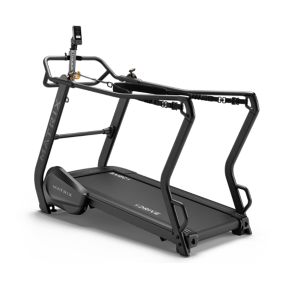
Summary of Contents for Matrix S-Drive
- Page 1 S - D r i v e P e r f o r m a n c e T r a i n e r S e r v i c e m a n U a l...
-
Page 2: Table Of Contents
Table of conTenTS cHaPTer 1: Serial nUmber locaTion ............1 cHaPTer 2: imPorTanT SafeTy inSTrUcTionS Read and Save These Instructions ................2 Before Getting Started ....................3 Tensioning and Centering the running belt ..............5 cHaPTer 3: PrevenTaTive mainTenance Recommended Cleaning Tips ................... 6 Check for Damaged Parts .................. -
Page 3: Chapter 1: Serial Number Location
cHaPTer 1: Serial nUmber locaTion 1.1 Serial nUmber locaTion Serial nUmber locaTion... -
Page 4: Chapter 2: Important Safety Instructions
cHaPTer 2: imPorTanT SafeTy inSTrUcTionS 2.1 reaD anD Save THeSe inSTrUcTionS When using a treadmill, basic precautions should always be followed, including the following: Read all instructions before using this treadmill. It is the responsibility of the owner to ensure that all users of this treadmill are adequately informed of all warnings and precautions. This product is intended for commercial use. -
Page 5: Before Getting Started
cHaPTer 2: imPorTanT SafeTy inSTrUcTionS 2.2 before GeTTinG STarTeD locaTinG THe UniT Place the treadmill on a level and stable surface away from direct sunlight. The intense UV light can cause discoloration on the plastics. Locate your treadmill in an area with cool temperatures and low humidity. Please leave a clear zone behind the treadmill that is at least the width of the treadmill and at least 79” (2000 mm) long. This zone must be clear of any obstruction and provide the user a clear exit path from the machine. - Page 6 cHaPTer 2: imPorTanT SafeTy inSTrUcTionS 2.2 before GeTTinG STarTeD - conTinUeD aDjUSTinG THe HarneSS After stepping onto the treadmill, slowly walk into the harness to check for proper height. The harness should sit comfortably at about waist height. If the harness needs to be adjusted, release the front connection point and reconnect the harness at the correct height SleD moDe Walk / SPrinT moDe HarneSS...
-
Page 7: Tensioning And Centering The Running Belt
cHaPTer 2: imPorTanT SafeTy inSTrUcTionS 2.3 TenSioninG anD cenTerinG THe rUnninG belT After placing the treadmill in the position it will be used, the belt must be checked for proper tension and centering. The belt might need to be adjusted after the first two hours of use. Temperature, humidity, and use cause the belt to stretch at different rates. If the belt starts to slip when a user is on it, be sure to follow the directions below. -
Page 8: Chapter 3: Preventative Maintenance
3. Walk on the machine at a comfortable speed for 3 minutes to spread the silicone and to check the running belt for proper tension and alignment. 4. Wipe any excess oil from the sides with a damp cloth. 3.2 cHeck for DamaGeD ParTS Do noT use any equipment that is damaged or has worn or broken parts. Use only replacement parts supplied by Matrix Fitness Systems. mainTain labelS anD namePlaTeS. Do not remove labels for any reason. They contain important information. If unreadable or missing, contact Matrix Fitness for a replacement at 866-693-4863 or www.matrixfitness.com. -
Page 9: Chapter 4: Troubleshooting
cHaPTer 4: TroUbleSHooTinG 4.1 no reSiSTance TroUbleSHooTinG 1) SymPTom: No resistance 2) SolUTion a. Open the frame cover and check whether the tension control works. b. When you adjust the tension control brake, please verify whether the wire moves and refer to the steps below to find the root cause. SPEED BRAKE (RIGHT SIDE) SLED BRAKE (LEFT SIDE) If the wire does not move, replace the SPEED BRAKE tension control If the wire does not move, replace the SLED BRAKE tension control Check the ECB and spring connection... -
Page 10: Chapter 5: Parts Replacement Guide
cHaPTer 5: ParTS rePlacemenT GUiDe 5.1 TenSion conTrol rePlacemenT 1) Remove the 2 screws holding frame cover (Figure A). 2) Take off the tension control wire (Figure B). fiGUre b fiGUre a 3) Remove the tension control wire from frame (Figure C). 4) Tie the wire on damaged tension control wire. When you pull out tension control wire, the wire will be inside console mast, so it is easier to replace new tension control wire (Figure D). fiGUre D fiGUre c 5) Remove the 6 screws holding arm rest set (Figure E & F). fiGUre f fiGUre e... - Page 11 cHaPTer 5: ParTS rePlacemenT GUiDe 5.1 TenSion conTrol rePlacemenT - conTinUeD 6) Put down the arm rest set (Figure G). 7) Remove the 2 screws holding tension control from arm rest set (Figure H). fiGUre H fiGUre G 8) Remove tension control from arm rest set (Figure I). fiGUre i 9) When you install the new tension control, make sure the tension control level is at the highest level and tie the wire at tension control wire end. Please refer to the figure J & K. fiGUre k fiGUre j...
-
Page 12: Side Rail Replacement
cHaPTer 5: ParTS rePlacemenT GUiDe 5.2 SiDe rail rePlacemenT 1) Remove the two screws holding on the support tube set and move the support tube set out (Figure A). 2) Remove the screw holding on the end cap and remove the end cap (Figure B). fiGUre b fiGUre a 3) Loosen the four screws under the frame of the side rail (Figure C). 4) Slide the rail to back of the treadmill (Figure D). fiGUre D fiGUre c 5) Reverse Step 1-4 to install a new side rail. NOTE: After reinstalling the side rail, make sure the end cap is on first before tightening the screws for proper gap spacing. Also be careful not to overtighten the screws, or they will poke through the top of the side rail. -
Page 13: Rear Roller Replacement
cHaPTer 5: ParTS rePlacemenT GUiDe 5.3 rear roller rePlacemenT 1) Remove the two screws holding on the support tube set and move the support tube set out (Figure A). 2) Remove the screw holding on the end cap and remove the end cap (Figure B). fiGUre b fiGUre a 3) Remove both roller adjustment screws (Figure C). 4) Remove the roller from the running belt (Figure D). fiGUre D fiGUre c 5) Reverse Step 1-4 to install a new rear roller. 6) Tension the running belt as outlined in Section 2.3. -
Page 14: Running Deck Replacement
cHaPTer 5: ParTS rePlacemenT GUiDe 5.4 rUnninG Deck rePlacemenT 1) Remove the side rail as outlined in Section 5.2 2) Loosen both roller adjustment screws (Figure A). 3) Remove the four running deck screws (Figure B). fiGUre b fiGUre a 4) Remove the running deck from the running belt (Figure C). NOTE: Be careful not to pinch fingers during removal / installation of the running deck. 5) Tension the running belt as outlined in Section 2.3. fiGUre c... -
Page 15: Running Belt Replacement
cHaPTer 5: ParTS rePlacemenT GUiDe 5.5 rUnninG belT rePlacemenT 1) Remove the side rail as outlined in Section 5.2. 2) Remove the rear roller as outlined in Section 5.3. 3) Remove the running deck as outlined in Section 5.4 4) Remove the front roller right side two screws (Figure A). 5) Once the rear rollers and deck are removed, the running belt can be lifted up from front roller right side (Figure B). fiGUre b fiGUre a 6) Reverse Step 1-5 to install a new running belt. 7) Tension the running belt as outlined in Section 2.3. -
Page 16: Running Deck Cushion Replacement
cHaPTer 5: ParTS rePlacemenT GUiDe 5.6 rUnninG Deck cUSHion rePlacemenT 1) Remove the running deck as outlined in Section 5.4. 2) Hold the running deck cushion bolt with a 5mm Allen wrench and loosen the nut with 13mm socket (Figure A). fiGUre a 3) Reverse Step 1-2 to install new running deck cushions. 4) Tension the running belt as outlined in Section 2.3. -
Page 17: Front Roller Replacement
cHaPTer 5: ParTS rePlacemenT GUiDe 5.7 fronT roller rePlacemenT 1) Remove the two screws holding frame cover (Figure A). 2) Loosen both roller adjustment screws (Figure B). fiGUre b fiGUre a 3) Remove the 4 screws on flywheel cover (Figure C). NOTE: One screw is at the bottom of the cover. fiGUre c... - Page 18 cHaPTer 5: ParTS rePlacemenT GUiDe 5.7 fronT roller rePlacemenT - conTinUeD 4) Remove the screw from flywheel set (Figure D). NOTE: Fix the front roller axle before removing the flywheel screw. 5) Use a crank puller tools to remove fly wheel set (Figure E). NOTE: 5-1 Please buy the crank puller in your local market. 5-2 Fix the front roller axle before removing the flywheel set (Figure F). fiGUre e fiGUre D 6) The flywheel set is very heavy, so when you take off flywheel from front roller axle, be careful not to drop the flywheel set as the ring will be easily damaged (Figure G). fiGUre G fiGUre f...
- Page 19 cHaPTer 5: ParTS rePlacemenT GUiDe 5.7 fronT roller rePlacemenT - conTinUeD 7) Remove the front roller mounting screws (Figure H). 8) Remove the roller from the running belt (Figure I). fiGUre i fiGUre H 9) Reverse Step 1-8 to install a new front roller. NOTE: When you install the new front roller, please make sure the roller housing is parallel with the tube. 10) Tension the running belt as outlined in Section 2.3. 11) When you run the belt, the flywheel ring may touch ECB magnet and make noise. Please loosen the ECB screw and adjust the flywheel ring between two magnets and fix screw (Figure K). fiGUre k fiGUre j...
-
Page 20: Ecb Replacement
cHaPTer 5: ParTS rePlacemenT GUiDe 5.8 ecb rePlacemenT 1) Remove the 2 screws holding frame cover (Figure A). 2) Remove the 4 screws on flywheel cover (Figure B). NOTE: One screw is at the bottom of the cover. fiGUre b fiGUre a 3) Remove the 2 screws from ECB (Figure C). 4) Take off the steel cable from ECB (Figure D). fiGUre D fiGUre c 5) Reverse Step 1-4 to install a new ECB. NOTE: When you fix ECB, make sure the inside spring is at the ECB screw right side (Figure E). fiGUre e... -
Page 21: Chapter 6: Treadmill Specifications And Assembly Guide
193 x 88 x 150 cm / (L x W x H)* 76” x 34.6” x 59” Max. Harness Loading 136 kg / 300 lbs * Ensure a minimum clearance width of 0.6 meters (24”) for access to and passage around MATRIX equipment. Please note, 0.91 meters (36”) is the ADA recommended clearance width for individuals in wheelchairs. 6.2 faSTenerS anD aSSembly ToolS ToolS reqUireD:... -
Page 22: Assembly Instructions
cHaPTer 6: TreaDmill SPecificaTionS anD aSSembly GUiDe 6.3 aSSembly inSTrUcTionS STeP 1 STeP 2 Black Hardware Bags (x2) Description Bolt Flat Washer Note: Do not fully tighten hardware until the end of step 5. Step 2 Torque Value: 78.4 Nm / 57.8 ft-lb There are no screws holding on the motor cover. Open Blue Assembly Bag. Slide the urethane arms over the steel tubes on the console base. - Page 23 cHaPTer 6: TreaDmill SPecificaTionS anD aSSembly GUiDe 6.3 aSSembly inSTrUcTionS - conTinUeD STeP 3 STeP 4 Red Hardware Bags (x2) White Hardware Bag Description Description C Bolt D Bolt Note: Note: Do not fully tighten hardware until the end of Do not fully tighten hardware until the end step 5.
- Page 24 cHaPTer 6: TreaDmill SPecificaTionS anD aSSembly GUiDe 6.3 aSSembly inSTrUcTionS - conTinUeD STeP 6 STeP 5 Green Hardware Bags (x2) Yellow Hardware Bag Description Description Bolt H Screw Flat Washer Bolt Note: Step 5 Torque Value: 39.2 Nm / 28.9 ft-lb A. Carefully pull the cable (1) through the riGHT HanDlebar SUPPorT using the twist tie located inside the riGHT HanDlebar SUPPorT and attach to the connecTor cable (2) on the main frame.
- Page 25 cHaPTer 6: TreaDmill SPecificaTionS anD aSSembly GUiDe 6.3 aSSembly inSTrUcTionS - conTinUeD STeP 8 STeP 7 aSSembly comPleTe! Note: Check that all harness connections are secure before use...
- Page 26 noTeS...
- Page 27 SS Sy S Te m S c or P. 1610 LAN DMARK D RI VE C OTTA G E G R OV E W I 5 352 7 U S A TOLL FREE 866.693.4863 w w w.m atri xf i tn es s .c om FA X 608 .8 39. 17 17...
Need help?
Do you have a question about the S-Drive and is the answer not in the manual?
Questions and answers