
Subscribe to Our Youtube Channel
Related Manuals for Matrix S-Force Performance Trainer


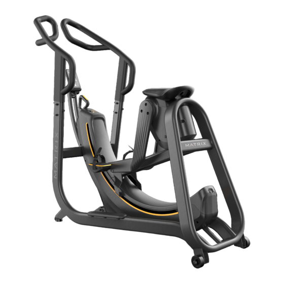
Summary of Contents for Matrix S-Force Performance Trainer
- Page 1 All manuals and user guides at all-guides.com S-Fo orce (S SPT) SERVIC CE MA ANUAL 1 ...
-
Page 2: Table Of Contents
All manuals and user guides at all-guides.com TABLE OF CONTENTS CHAPTER 1: SERIAL NUMBER LOCATION 1.1 Serial Number Location……..……………………………………………………………………………….………3 CHAPTER 2: IMPORTANT SAFETY INSTRUCTIONS 2.1 Read and Save These Instructions………….……………………………………………………………………4 2.2 Before Getting Started.....................5 CHAPTER 3: PREVENTATIVE MAINTENANCE 3.1 Care and Maintenance Instruction…………………….……………………………………………..…………6 3.2 Lubricating the magnets……………………………………………………………………………………………..6 CHAPTER 4: CONSOLE OVERLAY AND WORKOUT DESCRIPTION ... -
Page 3: Serial Numb Er Location
All manuals and user guides at all-guides.com APTER 1: SE ERIAL NUMB BER LOCATI ION 1.1 Serial Numb er Location 3 ... -
Page 4: Chapter 2: Important Safety Instructions
All manuals and user guides at all-guides.com CHAPTER 2: IMPORTANT SAFETY INSTRUCTIONS 2.1 Read and Save These Instructions • When using this equipment, basic precautions should always be followed, including the following: Read all instructions before using this equipment. It is the responsibility of the owner to ensure that all users of this equipment are adequately informed of all warnings and precautions. • This equipment is intended for commercial use. To ensure your safety and protect the equipment, read all instructions before operating. • Use the product for its intended purpose as described in this manual. Do not use attachments that have not been recommended by the manufacturer. • Never drop or insert any object into any opening in the product. If an object should drop inside, carefully retrieve it while the unit is not in use. If the item cannot be reached, contact Matrix Fitness or authorized dealers. • Never operate the product if it is not working properly, or if it has been damaged or immersed in water. Return it to Matrix Fitness or authorized dealers for examination and repair. • Keep hands and feet clear at all times from moving parts to avoid injury. • Do not reach into, or underneath the unit, and do not tip the unit on its side during operation. • Do not use the product outdoors, near swimming pools or in areas of high humidity. • Do not operate where aerosol (spray) products are being used or when oxygen is being administered. • Do not remove the covers. Service should only be done by an authorized service technician. • Close supervision is necessary when used near children, invalids or disabled people. • When the product is in use, young children and pets should be kept at least three meters / ten feet away. • Keep children under the age of 14 away from this equipment. Teenagers must be supervised at all ... -
Page 5: Before Getting Started
area with coo ol temperatu res nd low humid ity. Ensure a m minimum clea arance width o of 0.6 meters (24”) on each h side for acce ess to nd passage aro ound MATRIX X equipment. P Please note, 0 0.91 meters (3 36”) is the ADA A recommend ded earance width h for individua als in wheelch hairs. Do not p place the equi pment in any y area that wil l ock any vent or air opening gs. The equipm ment should n not be located d in a garage, ... -
Page 6: Chapter 3: Preventative Maintenance
All manuals and user guides at all-guides.com CHAPTER 3: PREVENTATIVE MAINTENANCE 3.1 Care and Maintenance Instruction 1) Any and all part removal or replacement must be performed by a qualified service technician. 2) DO NOT use any equipment that is damaged and or has worn or broken parts. Use only replacement parts supplied by your country’s local MATRIX dealer. 3) MAINTAIN LABELS AND NAMEPLATES: Do not remove labels for any reason. They contain important information. If unreadable or missing, contact your MATRIX dealer for a replacement. 4) MAINTAIN ALL EQUIPMENT: Preventative maintenance is the key to smooth operating equipment as well as keeping your liability to a minimum. Equipment needs to be inspected at regular intervals. 5) Ensure that any person(s) making adjustments or performing maintenance or repair of any kind is qualified to do so. MATRIX dealers will provide service and maintenance training at our corporate facility upon request. 3.2 Lubricating the Magnets 1) Use a coin to turn the release screw 90˚ clockwise. ... -
Page 7: Console Description
All manuals and user guides at all-guides.com APTER 4: CO ONSOLE OV VERLAY AND D WORKOUT T DESCRIPT TION 4.1 Console Desc cription Time Steps/ /min Disp Steps feedb back Distan... -
Page 8: Using Manager Mode
All manuals and user guides at all-guides.com APTER 5: M ANAGER M MODE 5.1 Using Manag ger Mode 1) Pr ress up and do own simultane eously for 5 se econds to ent ter manager m mode. ... -
Page 9: Chapter 5: Manager Mode
All manuals and user guides at all-guides.com CHAPTER 5: MANAGER MODE 5.2 Manager Mode Overview Group Item1 Item2 Default value Values/Range Unit Notes Max.Time 5-60 Minutes Default Time 1-60 Minutes 00:30 01:00 Workouts... -
Page 10: Electrical Diagrams
All manuals and user guides at all-guides.com APTER 6: TR ROUBLESHO OOTING 6.1 Electrical Dia agrams 1) SP PT electrical b lock diagrams s Figure A A 10 ... - Page 11 All manuals and user guides at all-guides.com APTER 6: TR ROUBLESHO OOTING 6.1 Electrical Dia agrams Contin nued 2) W Wire No. 1 in th he console Figure A Figure B 3) W Wire No. 2 in th he console ma ast FIGURE C ...
- Page 12 All manuals and user guides at all-guides.com APTER 6: TR ROUBLESHO OOTING 6.1 Electrical Dia agrams Contin nued 4) W Wire No. 3 in th he frame Figure E Figure F 5) Th he battery box x Figure G 12 ...
-
Page 13: Console Low Power
All manuals and user guides at all-guides.com APTER 6: TR ROUBLESHO OOTING 6.2 Console Low w Power 1) Th he display sho ows “Replace b battery” (Figu ure A). 2) Ch heck all conne ectors to make e sure they ar re properly co nnected. ... -
Page 14: Battery Replacement
All manuals and user guides at all-guides.com APTER 7: PA ARTS REPLA ACEMENT G UIDE 7.1 Battery Repl acement 1) Us se 6mm T‐Han ndle Allen Wr ench to remo ove the screw behind seat p pad (Figure A) 2) Pu ush the seat p pad backward (Figure B) 3) Pu ull upward to remove seatin ng pad (Figure e C) 4) Re eplace all batt teries. ... -
Page 15: Linkage Replacement
All manuals and user guides at all-guides.com APTER 7: PA ARTS REPLA ACEMENT G UIDE 7.2 Linkage Repl lacement 1) Af fter removing seating pad ( Section 7.1) , then please r remove top co over (Figure A A) and left/righ ht over (Figure B~ ~D) gure A ... - Page 16 All manuals and user guides at all-guides.com APTER 7: PA ARTS REPLA ACEMENT G UIDE 7.2 Linkage Repl lacement Con ntinued 3) Pu ull the lever to o Level 1 (Figu ure G) and the en remove cra ank (Figure H~ ~J) ...
- Page 17 All manuals and user guides at all-guides.com APTER 7: PA ARTS REPLA ACEMENT G UIDE 7.2 Linkage Repl lacement Con ntinued 5) Af fter removing the nut, use t the tool (MTU U‐0000347‐8) (Figure K) to s separate the l linkage and sh haft igure K). ...
-
Page 18: Sensor Replacement
All manuals and user guides at all-guides.com APTER 7: PA ARTS REPLA ACEMENT G UIDE 7.3 Sensor Repla acement 1) Re emove Right C Cover (Figure A~D) ... -
Page 19: Magnetic Plate Replacement
All manuals and user guides at all-guides.com APTER 7: PA ARTS REPLA ACEMENT G UIDE 7.4 4 Magnetic Pla ate Replacem ent 1) Re emove Right C Cover (Section n 7.3). 2) Re emove and re place the mag gnetic plate (F Figure A). Take e note that th e gap betwee... -
Page 20: Magnetic Carriage Replacement
All manuals and user guides at all-guides.com APTER 7: PA ARTS REPLA ACEMENT G UIDE 7.5 Magnetic Ca rriage Replac ement 1) Pu ush the lever t to Level 5 (Fig gure A) and re emove lower a arc cover (Figu ure B). 2) Re emove the scr rews and then n take the carr... -
Page 21: Copper Blade Replacement
All manuals and user guides at all-guides.com APTER 7: PA ARTS REPLA ACEMENT G UIDE 7.6 6 Copper Blade e Replacemen nt 1) Re emove upper and lower arc c covers (Figur re A~B). ... - Page 22 All manuals and user guides at all-guides.com APTER 7: PA ARTS REPLA ACEMENT G UIDE 7.6 6 Copper Blade e Replacemen nt Continued 4) Re emove the scr rew as in Figu re F, and remo ove the right c copper blade. F igure F ...
-
Page 23: Console Mast Replacement
All manuals and user guides at all-guides.com APTER 7: PA ARTS REPLA ACEMENT G UIDE 7.7 Console Mas st Replacemen nt 1) Re emove the scr rews, and the n remove the connector. 2) In stall the new mast. ... -
Page 24: Console Replacement
All manuals and user guides at all-guides.com APTER 7: PA ARTS REPLA ACEMENT G UIDE 7.8 8 Console Rep lacement 1) Re emove the scr rews and the c console conne ectors. 2) In stall the new console. Figure A ... -
Page 25: Lever Replacement
All manuals and user guides at all-guides.com APTER 7: PA ARTS REPLA ACEMENT G UIDE 7.9 9 Lever Replac cement 1) Re emove plastic cover (Sectio on 7.6 1) & 2) ) ), and the leve er (Figure A~B B). 2) Af fter installing ... -
Page 26: Chapter 8: Specifications And Assembly Guide
All manuals and user guides at all-guides.com CHAPTER 8: SPECIFICATIONS AND ASSEMBLY GUIDE 8.1 Production Specification CONSOLE Display Screen Extra‐large LCD display Time, Distance, SPM (strokes per minute), Display Readout Stroke, HR(B.P.M) Programs Manual, Interval, Challenge Telemetric Receiver No TECHNICAL DATA Resistance Technology Magnetic resistance ... -
Page 27: Assembly Instructions
All manuals and user guides at all-guides.com APTER 8: SP PECIFICATIO ONS AND AS SSEMBLY GU UIDE 8.3 Assembly Ins structions 1) ST TEP 1: Handle bar assembly y ... - Page 28 All manuals and user guides at all-guides.com APTER 8: SP PECIFICATIO ONS AND AS SSEMBLY GU UIDE 8.3 Assembly Ins structions Con ntinued 2) ST TEP 2: Console e mast assem bly DESCRIPTIO M6 Bolt Spring Was sher Flat Washe rque Values :98Kg.Cm ...
Need help?
Do you have a question about the S-Force Performance Trainer and is the answer not in the manual?
Questions and answers