
Related Manuals for Brocade Communications Systems Brocade TurboIron 24 Series


Summary of Contents for Brocade Communications Systems Brocade TurboIron 24 Series
- Page 1 HARDWARE INSTALLATION GUIDE Brocade TurboIron 24X Series Hardware Installation Guide Part Number: 53-1003053-03 Publication Date: 15 June 2017...
- Page 2 The authors and Brocade Communications Systems, Inc. assume no liability or responsibility to any person or entity with respect to the accuracy of this document or any loss, cost, liability, or damages arising from the information contained herein or the computer programs that accompany it.
-
Page 3: Table Of Contents
Contents Preface Document conventions ....................7 Text formatting conventions . - Page 4 ................. . 32 Configuring IP addresses .
- Page 5 ................61 Power supply specifications .
- Page 6 Brocade TurboIron 24X Series Hardware Installation Guide Part Number: 53-1003053-03...
-
Page 7: Preface
Preface • Document conventions ................7 •... -
Page 8: Notes, Cautions, And Warnings
Preface Brocade resources { x | y | z } A choice of required parameters is enclosed in curly brackets separated by vertical bars. You must select one of the options. In Fibre Channel products, square brackets may be used instead for this purpose. x | y A vertical bar separates mutually exclusive elements. -
Page 9: Contacting Brocade Technical Support
Preface Contacting Brocade Technical Support Contacting Brocade Technical Support As a Brocade customer, you can contact Brocade Technical Support 24x7 online, by telephone, or by e-mail. Brocade OEM customers contact their OEM/Solutions provider. Brocade customers For product support information and the latest information on contacting the Technical Assistance Center, go to http://www.brocade.com/services-support/index.html. - Page 10 Preface Document feedback Brocade TurboIron 24X Series Hardware Installation Guide Part Number: 53-1003053-03...
-
Page 11: About This Document
About this Document • What’s new in this document ................11 What’s new in this document There is no enhancements in this edition. - Page 12 About this Document What’s new in this document Brocade TurboIron 24X Series Hardware Installation Guide Part Number: 53-1003053-03...
-
Page 13: Product Overview
Product Overview This chapter contains the following sections: • Product overview ..................13 •... -
Page 14: Control Features
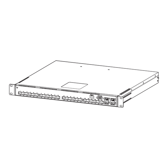
Product Overview Hardware features Figure 1 shows the TurboIron 24X. FIGURE 1 TurboIron 24X TurboIron 24X contains the following ports: • Twenty-four (24) SFP+ 10 Gigabit and Gigabit Ethernet fiber ports • Four (4) 10/100/1000 Mbps copper ports, supporting 100Base-TX and 1000Base-T RJ-45 connectors Control features TurboIron 24X front panel has the following control features: •... -
Page 15: Network Interfaces
Product Overview Hardware features Network interfaces Table 1 describes the network interfaces supported on TurboIron 24X devices. TABLE 1 Network interfaces Interface Show Media Description 1000Base-BX-D M-GBXD 1000Base-BX-U M-GBXU 1000Base-LHA M-LHA 1000Base-LHB M-LHB 1000Base-LX M-LX 1000Base-SX M-SX 1000Base-SX2 M-SX2 1000Base-T 100Base-TX 10GBase-LR XG-LR... -
Page 16: Leds For Network Interfaces And Power Supplies
Product Overview Hardware features Port 17: Type : EMPTY Port 18: Type : EMPTY Port 19: Type : 10G XG-SR(SFP+) Vendor: Brocade Version: 1 Part# : PLRXPLSCS4371 Serial#: xxxxxxxxx Port 20: Type : 10G XG-SR(SFP+) Vendor: Brocade Version: 1 Part# : PLRXPLSCS4371 Serial#: xxxxxxxxx Port 21: Type : EMPTY Port 22: Type : EMPTY Port 23: Type : EMPTY... -
Page 17: Power Supplies
Product Overview Hardware features • The Management port has a Link LED and Activity LED to indicate port status. The Link LED is on the left of the copper connector and the Activity LED is on the right. • The System power on LED is on the left side of the front panel. •... - Page 18 Product Overview Hardware features Figure 4 shows the front panel of the AC power supplies used in the TurboIron 24X (at the rear of the device). FIGURE 4 AC power supply front panel AC LED The power supplies are auto-sensing and auto-switching, and provide up to 300 watts of total output power, having a universal input (90 VAC to 264 VAC) and 12 VDC regulated output.
-
Page 19: Installing The Turboiron 24X
Installing the TurboIron 24X This chapter contains the following sections: • Unpacking a system ................. . 19 •... -
Page 20: Summary Of Installation Tasks
Installing the TurboIron 24X Summary of installation tasks Summary of installation tasks Follow the steps listed below to install your TurboIron 24X device. Details for each of these steps are provided in this chapter and in the following chapter. TABLE 1 Summary of installation tasks Task No. -
Page 21: Lifting Precautions
Installing the TurboIron 24X Installation precautions Make sure that air flow around the front, sides, and back of the device is not restricted. Never leave tools inside the device. Use the erase startup-config command only for new systems. If you enter this command on a system you have already configured, the command erases the configuration. - Page 22 Installing the TurboIron 24X Installation precautions Use a separate branch circuit for each AC power cord, to provide redundancy in case one of the circuits fails. Ensure that the device does not overload the power circuits, wiring, and over-current protection. To determine the possibility of overloading the supply circuits, add the ampere (amp) ratings of all devices installed on the same circuit as the device.
-
Page 23: Preparing The Installation Site
Installing the TurboIron 24X Preparing the installation site Risk of explosion if battery is replaced by an incorrect type. Replace the battery only with the same or equivalent type recommended by the manufacturer. Dispose of used battery according to the instructions. Disconnect the power cord from all power sources to completely remove power from the device. -
Page 24: Installation Location
Installing the TurboIron 24X Installing the device Installation location Before installing the device, plan its location and orientation relative to other devices and equipment. Allow at least 3 in. of space at the front of the device for the twisted-pair, fiber-optic, and power cabling. Also, allow a minimum of 3 in. of space between the sides and the back of the device and walls or other obstructions. - Page 25 Installing the TurboIron 24X Installing the device Mount the devices you install in a rack or cabinet as low as possible. Place the heaviest device at the bottom and progressively place lighter devices above. Mechanical Loading - Mounting of the equipment in the rack should be such that a hazardous condition is not achieved due to uneven mechanical loading.
- Page 26 Installing the TurboIron 24X Installing the device Attach a rack-mount bracket to one side of the Network switch with the supplied screws. Then attach the other bracket to the other side. Make sure you use the screws supplied with the mounting brackets. Using the wrong screws could damage the TurboIron 24X and would invalidate your warranty.
-
Page 27: Powering On The System
Installing the TurboIron 24X Powering on the system Powering on the system Note the following before powering on the system: • The socket should be installed near the equipment and should be easily accessible. • If the outlet is not rated 115 or 120V, stop and get the appropriate cable for the outlet. •... -
Page 28: Observing The Power Status Leds
Installing the TurboIron 24X Attaching a PC or terminal 10G port LEDs should be lit while the device performs diagnostics. After the diagnostics are complete, the LEDs will be dark except for those that are attached by cables to other devices. If the links on these cables are good and the connected device is powered on, the link LEDs will light. - Page 29 Installing the TurboIron 24X Attaching a PC or terminal • Data bits: 8 • Parity: None • Stop bits: 1 • Flow control: None When you establish the serial connection to the system, press Enter to display the CLI prompt in the terminal emulation window. For example, TurboIron>...
- Page 30 Installing the TurboIron 24X Attaching a PC or terminal FIGURE 5 Serial port pin assignments showing cable connection options to a terminal or PC DB-9 to DB-9 DB-9 to DB-25 Terminal or PC Terminal or PC Female Switch Female Switch Reserved Reserved Reserved...
-
Page 31: Connecting Network Devices And Checking Connectivity
Connecting Network Devices and Checking Connectivity This chapter contains the following sections: • Assigning permanent passwords ..............31 •... -
Page 32: Recovering From A Lost Password
Connecting Network Devices and Checking Connectivity Configuring IP addresses At the opening CLI prompt, enter the following command to change to the Privileged level of the EXEC mode. TurboIron> enable Access the configuration level of the CLI by entering the following command. TurboIron# configure terminal TurboIron(config)# Enter the following command to set the Super User password. -
Page 33: Devices Running Layer 2 Software
Connecting Network Devices and Checking Connectivity Configuring IP addresses • To enter a classical network mask, enter the mask in IP address format. For example, enter, "10.157.22.99 255.255.255.0" for an IP address with a Class-C subnet mask. • To enter a prefix number for a network mask, enter a forward slash ( /) and the number of bits in the mask immediately after the IP address. -
Page 34: Connecting Network Devices
Connecting Network Devices and Checking Connectivity Connecting network devices Connecting network devices Brocade devices support connections to routers, switches, and hubs from other vendors, as well as other Brocade devices. Connectors and cable specifications Refer to <Link>“Cable specifications” on page 53 for cable lengths and types supported on the TurboIron 24X devices. For port pinouts, refer to <Link>“10/100/1000 Gigabit port pinouts”... -
Page 35: Connecting To Workstations, Servers, Or Routers
Connecting Network Devices and Checking Connectivity Connecting network devices NOTE The 802.3ab standard calls for automatic negotiation of the connection between two 1000Base-T ports. Consequently, a crossover cable may not be required; a straight-through cable may work as well. Connecting to workstations, servers, or routers Straight-through UTP cabling is required for direct UTP attachment to workstations, servers, or routers using network interface cards (NICs). -
Page 36: Testing Connectivity
Connecting Network Devices and Checking Connectivity Testing connectivity Gently insert the fiber optic module into the port until the module clicks into place. The module is keyed to prevent incorrect insertion. Cabling a fiber optic module Follow the steps to cable a fiber optic module. Remove the protective covering from the fiber-optic port connectors and store the covering for future use. -
Page 37: Tracing A Route
Connecting Network Devices and Checking Connectivity Testing connectivity TABLE 1 Network connection-related LED states Desired State Meaning Abnormal Meaning or Action State Link On (Green) A link is established A link is not established with the remote port. (Lnk) with the remote port. You can do the following: •... -
Page 38: Troubleshooting Network Connections
Connecting Network Devices and Checking Connectivity Troubleshooting network connections Troubleshooting network connections • For the indicated port, verify that both ends of the cabling (at the TurboIron device and the connected device) are snug. • Verify that the TurboIron device and the connected device are both powered on and operating correctly. •... -
Page 39: Managing The Turboiron 24X
Managing the TurboIron 24X This chapter contains the following sections: • Managing temperature settings ............... . 39 •... -
Page 40: Displaying Temperature Messages
Managing the TurboIron 24X Managing temperature settings Displaying temperature messages The software sends a Syslog message and an SNMP trap if the temperature crosses the warning threshold. The following methods describe how to view the system log on the device. If you have configured the device to use a Syslog server or SNMP trap receiver, refer to the documentation for the server or receiver. -
Page 41: Removing Mac Address Entries
Managing the TurboIron 24X Removing MAC address entries Removing MAC address entries You can remove learned MAC address entries from the Brocade system MAC address table. You can remove the following entries: • All MAC address entries • All MAC address entries for a specified Ethernet port •... - Page 42 Managing the TurboIron 24X Removing MAC address entries Brocade TurboIron 24X Series Hardware Installation Guide Part Number: 53-1003053-03...
-
Page 43: Maintaining The Turboiron 24X Hardware
Maintaining the TurboIron 24X Hardware This chapter contains the following sections: • Hardware maintenance schedule ..............43 •... -
Page 44: Installing A New Fiber Optic Module
Maintaining the TurboIron 24X Hardware Replacing a fiber optic module • An ESD wrist strap with a plug for connection to the ESD connector on the TurboIron 24X. For safety reasons, the ESD wrist strap should contain a series 1 meg ohm resistor. •... -
Page 45: Cabling A Fiber Optic Module
Maintaining the TurboIron 24X Hardware Replacing a power supply To install a fiber optic module, you will need an ESD wrist strap with a plug for connection to a metal surface. For safety reasons, the ESD wrist strap should contain a series 1 meg ohm resistor. Follow the steps to install a fiber optic module. -
Page 46: Installation Precautions And Warnings
Maintaining the TurboIron 24X Hardware Replacing a power supply • Replacing a power supply Power supplies are hot swappable. However, Brocade recommends that you disconnect the power supply from AC power before installing or removing the supply. The device can be running while a power supply is being installed or removed, but the power supply itself should not be connected to a power source. -
Page 47: Ac Power Supplies
Maintaining the TurboIron 24X Hardware Replacing a power supply AC power supplies Use the following procedures for AC power supplies in TurboIron 24X devices. Before beginning the installation, refer to the precautions in “Power precautions” on page 12. You will need a #2 Phillips-head screwdriver to perform these procedures. Figure 3 shows a front view of the AC power supply. -
Page 48: Installing An Ac Power Supply
Maintaining the TurboIron 24X Hardware Replacing a power supply FIGURE 5 Removing the power supply Place the power supply in an anti-static bag for storage. Installing an AC power supply NOTE If the empty power supply bay has a cover plate, remove it as shown below before continuing. FIGURE 6 Releasing the cover plate Brocade TurboIron 24X Series Hardware Installation Guide... - Page 49 Maintaining the TurboIron 24X Hardware Replacing a power supply FIGURE 7 Removing the cover plate Remove the new power supply from its packaging. Hold the bar on the front panel of the power supply with one hand and ensure that the cotter pin on the right side of the power supply is correctly aligned.
- Page 50 Maintaining the TurboIron 24X Hardware Replacing a power supply FIGURE 8 Installing the power supply Lock the power supply in place by securing the two captive screws as shown in Figure FIGURE 9 Securing the power supply in the device Connect the power cord to the power supply.
-
Page 51: Replacing The Fan Tray
Maintaining the TurboIron 24X Hardware Replacing the fan tray FIGURE 10 Connecting the power cord Power on the supply and verify that it is working properly as instructed in “Powering on the system” on page 18 and “Verifying proper operation” on page 19. -
Page 52: Removing The Fan Tray
Maintaining the TurboIron 24X Hardware Replacing the fan tray Removing the fan tray Use the following procedures to remove the fan tray from TurboIron 24X devices. Figure 11 shows the location of the fan tray. FIGURE 11 TurboIron 24X fan tray location Fan Tray Disconnect the power cord from the power supply. - Page 53 Maintaining the TurboIron 24X Hardware Replacing the fan tray FIGURE 13 Inserting a replacement fan tray Locating Slide Connect the power cord to the power supply (refer to “Powering on the system” on page 18). Verify that the system is working properly as instructed in “Verifying proper operation”...
- Page 54 Maintaining the TurboIron 24X Hardware Replacing the fan tray Brocade TurboIron 24X Series Hardware Installation Guide Part Number: 53-1003053-03...
-
Page 55: Hardware Specifications
Hardware Specifications This appendix contains the following sections: • Device specifications ................. 55 •... -
Page 56: Environmental Considerations
Hardware Specifications Device specifications TABLE 1 Physical dimensions and weight of the TurboIron 24X and modules Platform Height Width Depth Weight • TurboIron 24X (4.28 cm) 1.68 in. (43.5 cm) 17.12 in. (39.37 cm) 15.5 in. (7.4 kg) 16.28 lbs including dual power supplies •... -
Page 57: Regulatory Compliance
Hardware Specifications Device specifications FIGURE 1 Device air flow Left intake Right intake Front intakes Exhaust • Total cooling capacity: 200 watts • Total air flow: 150 LFM • Fan operating noise: < 65 dB-A. NOTE Operating noise is based on the ISO 7779 standard. Regulatory compliance Table 4 lists the Electromagnetic Compatibility (EMC), Immunity standards, and safety agency approvals for TurboIron 24X switches. -
Page 58: Mean Time Between Failure
Hardware Specifications Device specifications TABLE 5 Device power surge and drop protection Property Protection Mechanism Power surge MOV and Spark Gap protection Power drop The PSU will shut down after AC loss >20ms Maximum power draw 300 watts Mean time between failure Table 6 lists the Mean Time between Failure (MTBF) for the TurboIron 24X. -
Page 59: Cable Specifications
Hardware Specifications Device specifications FIGURE 3 Serial port pin assignments showing cable connection options to a terminal or PC DB-9 to DB-9 DB-9 to DB-25 Terminal or PC Terminal or PC Female Switch Female Switch Reserved Reserved Reserved Reserved Reserved Reserved Reserved Reserved... -
Page 60: Power Cords
Hardware Specifications Device specifications TABLE 7 Cable length summary Cable Type Connector Type Core Diameter Modal Range (meters) (microns) Bandwidth (MHz*km) or Wavelength (nm) 1000Base-BX-D Single-mode LC connector for 1490 nm 2 - 10000 Fiber (SMF) SFP module (10 km) 1000Base-BX-U LC connector for 1310 nm... -
Page 61: Power Supply Specifications
Hardware Specifications Power supply specifications For power cord specifications, refer to “Input connector and plug” on page 62. Power supply specifications This section contains the following information for the power supplies that ship with TurboIron 24X devices. • “Overview” • “Key features”... -
Page 62: Environmental Considerations
Hardware Specifications Power supply specifications Environmental considerations For optimal performance, operate or store the power supplies in compliance with the following environmental conditions. Operating environment TABLE 9 Operating environmental conditions for power supplies Description Range Operating temperature 0° - 40°C (32° - 104°F) Fan inlet temperature 43°... -
Page 63: Regulatory Compliance
Hardware Specifications Power supply specifications FIGURE 5 AC power cord plug and input connector Regulatory compliance The power supplies comply with the conducted and radiated test, immunity, and safety standards as listed in Table TABLE 12 Power supply regulatory compliance Description Certifications •... -
Page 64: Electrical Specifications
Hardware Specifications Power supply specifications TABLE 13 Safety warning labels on power supplies ATTENZIONE Non aprire. Rivolgersi a personale qualificado. CUIDADO Partes adentro no reparables por el operador. Refiera reparo a personal autorizado. ATTENTION Entretien et répartions internes ne sont autorisés qu'au personnel technique qualifié. GEFAHR Zugang zur Bedienung nicht erförderlich. -
Page 65: Regulatory Approval And Statements
Regulatory Approval and Statements This appendix contains the following sections: • Agency approvals ..................65 •... -
Page 66: Regulatory Statements
Regulatory Approval and Statements Regulatory statements Regulatory statements U.S.A. This equipment has been tested and found to comply with the limits for a Class A digital device pursuant to Part 15 of the FCC Rules. These limits are designed to provide reasonable protection against harmful interference when the equipment is operated in a commercial environment. -
Page 67: Japan Power Cord
Regulatory Approval and Statements Regulatory statements Japan power cord English translation of above statement ATTENTION: Never use the power cord packed with your equipment for other products. Korea A 급 기기 ( 업무용 방송통신기기 ): 이 기기는 업무용 (A 급 ) 으로 전자파적합등록 을... -
Page 68: China
Regulatory Approval and Statements Regulatory statements China China-CCC Warning statements 在维修的时候一定要断开所有电源 (English translation“disconnect all power sources before service”) For non tropical use: 汉文 “仅适用于非热带气候条件下安全使用。” 藏文 安全 蒙古 说明 文 和标 Dan hab yungh youq gij dienheiq diuzgen mbouj dwg diegndat 壮文 记 ... -
Page 69: Bsmi Statement (Taiwan)
Regulatory Approval and Statements Regulatory statements BSMI statement (Taiwan) English translation of above statement Warning: This is a class A product. In a domestic environment this product may cause radio interference in which case the user may be required to take adequate measures. China RoHS Restriction on the use of certain hazardous substances in electrical and electronic equipment. - Page 70 Regulatory Approval and Statements Regulatory statements Brocade TurboIron 24X Series Hardware Installation Guide Part Number: 53-1003053-03...
-
Page 71: Caution And Danger Notices Cautions
Caution and Danger Notices This appendix contains the following sections: • Cautions ................... . 71 •... - Page 72 Caution and Danger Notices Cautions CAUTION Make sure the air flow around the front, sides, and back of the device is not restricted. VORSICHT Stellen Sie sicher, dass an der Vorderseite, den Seiten und an der Rückseite der Luftstrom nicht behindert wird. MISE EN GARDE Vérifiez que rien ne restreint la circulation d'air devant, derrière et sur les côtés du dispositif et qu'elle peut se faire librement.
- Page 73 Caution and Danger Notices Cautions CAUTION Use the erase startup-config command only for new systems. If you enter this command on a system you have already configured, the command erases the configuration. If you accidentally do erase the configuration on a configured system, enter the write memory command to save the running configuration to the startupconfig file.
-
Page 74: Danger
Caution and Danger Notices Danger CAUTION Danger of explosion if battery is incorrectly replaced. Replace only with the same or equivalent type recommended by the manufacturer. Dispose of used batteries according to the manufacturer's instructions. VORSICHT Explosionsgefahr bei unsachgemäßem Austausch der Batterie. Ersatz nur durch den selben oder einen vom Hersteller empfohlenen gleichwertigen Typ. - Page 75 Caution and Danger Notices Danger DANGER Disconnect the power cord from all power sources to completely remove power from the device. GEFAHR Ziehen Sie das Stromkabel aus allen Stromquellen, um sicherzustellen, dass dem Gerät kein Strom zugeführt wird. DANGER Débranchez le cordon d'alimentation de toutes les sources d'alimentation pour couper complètement l'alimentation du dispositif.
- Page 76 Caution and Danger Notices Danger DANGER Power supplies are hot swappable, which means they can be removed and replaced while the chassis is powered on and running. However, Brocade recommends that you disconnect the power supply from the wall outlet before removing and replacing the supply.
- Page 77 Caution and Danger Notices Danger DANGER Be careful not to accidently insert your fingers into the fan tray while removing it from the chassis. The fan may still be spinning at a high speed. GEFAHR Die Finger dürfen nicht versehentlich in das Ventilatorblech gesteckt werden, wenn dieses vom Gehäuse abgenommen wird.
- Page 78 Caution and Danger Notices Danger Brocade TurboIron 24X Series Hardware Installation Guide Part Number: 53-1003053-03...
Need help?
Do you have a question about the Brocade TurboIron 24 Series and is the answer not in the manual?
Questions and answers