
Related Manuals for Brocade Communications Systems NetIron CES 2000 Series


Summary of Contents for Brocade Communications Systems NetIron CES 2000 Series
- Page 1 53-1003823-01 18 August 2015 Brocade NetIron CES 2000 Series and NetIron CER 2000 Series Hardware Installation Guide Supported Release: Multi-Service IronWare R05.9.00...
- Page 2 United States government. The authors and Brocade Communications Systems, Inc. assume no liability or responsibility to any person or entity with respect to the accuracy of this document or any loss, cost, liability, or damages arising from the information contained herein or the computer programs that accompany it.
-
Page 3: Table Of Contents
Connecting to a Network Device ....................37 Password assignment..................37 IP address configuration................. 38 Support of sub-net masks..............39 Assigning an IP address to a management interface......39 Brocade NetIron CES 2000 Series and NetIron CER 2000 Series Hardware Installation Guide 53-1003823-01... - Page 4 Storage environment ..................74 Cooling......................75 Safety agency approvals................75 Electromagnetic approvals................75 Port specifications..................75 Console port pin assignments............76 Management port pin assignments........... 77 Hardware Maintenance......................79 Hardware maintenance schedule..............79 Brocade NetIron CES 2000 Series and NetIron CER 2000 Series Hardware Installation Guide 53-1003823-01...
- Page 5 Europe and Australia (CISPR 22 Class A Warning)........98 FCC warning (US only)................... 99 Germany......................99 KCC statement (Republic of Korea)..............99 VCCI statement....................99 Caution and Danger Notices....................101 Cautions......................101 Danger Notices..................... 108 Index............................ 115 Brocade NetIron CES 2000 Series and NetIron CER 2000 Series Hardware Installation Guide 53-1003823-01...
- Page 6 Brocade NetIron CES 2000 Series and NetIron CER 2000 Series Hardware Installation Guide 53-1003823-01...
-
Page 7: Preface
Identifies a variable. value In Fibre Channel products, a fixed value provided as input to a command option is printed in plain text, for example, --show WWN. Brocade NetIron CES 2000 Series and NetIron CER 2000 Series Hardware Installation Guide 53-1003823-01... -
Page 8: Notes, Cautions, And Warnings
A Danger statement indicates conditions or situations that can be potentially lethal or extremely hazardous to you. Safety labels are also attached directly to products to warn of these conditions or situations. Brocade NetIron CES 2000 Series and NetIron CER 2000 Series Hardware Installation Guide 53-1003823-01... -
Page 9: Brocade Resources
• OEM/Solution Providers are trained and certified by Brocade to support Brocade products. • Brocade provides backline support for issues that cannot be resolved by the OEM/Solution Provider. Brocade NetIron CES 2000 Series and NetIron CER 2000 Series Hardware Installation Guide 53-1003823-01... -
Page 10: Document Feedback
Provide the publication title, part number, and as much detail as possible, including the topic heading and page number if applicable, as well as your suggestions for improvement. Brocade NetIron CES 2000 Series and NetIron CER 2000 Series Hardware Installation Guide 53-1003823-01... -
Page 11: About This Document
Brocade NetIron CES 2024F-4X Brocade NetIron CER 2024F-4X-RT Brocade NetIron CES 2048C Brocade NetIron CES 2048CX EOL initiated Brocade NetIron CES 2048F Brocade NetIron CES 2048FX EOL initiated Brocade NetIron CES 2000 Series and NetIron CER 2000 Series Hardware Installation Guide 53-1003823-01... -
Page 12: Supported Software
Many commands from previous NetIron releases are also included in the command reference. • Legacy content in configuration guides continues to include command syntax and parameter descriptions in the chapters where the features are documented. Brocade NetIron CES 2000 Series and NetIron CER 2000 Series Hardware Installation Guide 53-1003823-01... -
Page 13: Notice To The Reader
• Brocade MLXe Series Installation Guide • Brocade MLX Series and Brocade NetIron XMR Installation Guide • Brocade NetIron CES 2000 Series and Brocade NetIron CER 2000 Series Hardware Installation Guide Brocade NetIron CES 2000 Series and NetIron CER 2000 Series Hardware Installation Guide... - Page 14 Related publications Brocade NetIron CES 2000 Series and NetIron CER 2000 Series Hardware Installation Guide 53-1003823-01...
-
Page 15: Product Overview
• Brocade NetIron CES Series 2048C -- accommodates 48-port 10/100/1000 RJ45 model with 4 combination 100/1000 Hybrid Fiber (HF) ports • Brocade NetIron CES Series 2048CX -- accommodates 48-port 10/100/1000 RJ45 model with 2x10G XFP uplink ports Brocade NetIron CES 2000 Series and NetIron CER 2000 Series Hardware Installation Guide 53-1003823-01... - Page 16 FIGURE 1 Brocade NetIron CES Series 2024C-4X FIGURE 2 Brocade NetIron CES Series 2024F-4X FIGURE 3 Brocade NetIron CES Series 2024C FIGURE 4 Brocade NetIron CES Series 2024F Brocade NetIron CES 2000 Series and NetIron CER 2000 Series Hardware Installation Guide 53-1003823-01...
- Page 17 FIGURE 7 Brocade NetIron CES Series 2048CX FIGURE 8 Brocade NetIron CES Series 2048FX There are also fourteen models in the NetIron Carrier Ethernet Router (CER and CER-RT) 2000 Series: Brocade NetIron CES 2000 Series and NetIron CER 2000 Series Hardware Installation Guide 53-1003823-01...
- Page 18 2x10G XFP uplink ports. This device has the ability to simultaneously store up to 1.5 million IPv4 routes and up to 256,000 IPv6 routes FIGURE 9 Brocade NetIron CER Series 2024C-4X-RT FIGURE 10 Brocade NetIron CER Series 2024F-4X-RT Brocade NetIron CES 2000 Series and NetIron CER 2000 Series Hardware Installation Guide 53-1003823-01...
- Page 19 Product Overview FIGURE 11 Brocade NetIron CER Series 2024C FIGURE 12 Brocade NetIron CER Series 2024F FIGURE 13 Brocade NetIron CER Series 2048C Brocade NetIron CES 2000 Series and NetIron CER 2000 Series Hardware Installation Guide 53-1003823-01...
-
Page 20: Product Overview
2000 Series addresses a diverse set of applications in metro edge networks, ISP networks, mobile backhaul networks, data centers, large enterprises, government networks and education or research. Brocade NetIron CES 2000 Series and NetIron CER 2000 Series Hardware Installation Guide 53-1003823-01... -
Page 21: Software Features
Series or Brocade NetIron CER Series 2000 Series device with the premium software already installed. For more information, refer to the Multi-Service IronWare Software Upgrade Guide . Brocade NetIron CES 2000 Series and NetIron CER 2000 Series Hardware Installation Guide 53-1003823-01... -
Page 22: Hardware Features
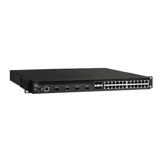
AC power supply included. FIGURE 19 Brocade NetIron CES Series 2024C-4X device 10 GbE SFP+ ports Four combination 100/1000 MbE SFP ports Twenty-four 10/100/1000 MbE RJ45 ports Brocade NetIron CES 2000 Series and NetIron CER 2000 Series Hardware Installation Guide 53-1003823-01... -
Page 23: Brocade Netiron Ces Series 2024F-4X
10/100/1000 MbE RJ45 ports, one module slot for an optional field upgradable 2-port 10 GbE XFP module, one DB9 serial management interface port labeled Console, one 10/100/1000 MbE Brocade NetIron CES 2000 Series and NetIron CER 2000 Series Hardware Installation Guide 53-1003823-01... -
Page 24: Brocade Netiron Ces Series 2048C
10 GbE XFP ports, one DB9 serial management interface port labeled Console, one 10/100/1000 MbE RJ45 out-of-band management port, one resilient six-unit fan tray, and two AC power supply bays for 1+1 redundancy with one 500W AC power supply included. Brocade NetIron CES 2000 Series and NetIron CER 2000 Series Hardware Installation Guide 53-1003823-01... -
Page 25: Brocade Netiron Ces Series 2048F
RJ45 out-of-band management port, one resilient six-unit fan tray, and two AC power supply bays for 1+1 redundancy with one 500W AC power supply included. FIGURE 26 Brocade NetIron CES Series 2048FX device Brocade NetIron CES 2000 Series and NetIron CER 2000 Series Hardware Installation Guide 53-1003823-01... -
Page 26: Brocade Netiron Cer Series 2024C
Console, one 10/100/1000 MbE RJ45 out-of-band management port, one resilient six-unit fan tray, and two AC power supply bays for 1+1 redundancy with one 500W AC power supply included. Brocade NetIron CES 2000 Series and NetIron CER 2000 Series Hardware Installation Guide 53-1003823-01... -
Page 27: Brocade Netiron Cer Series 2048C
Brocade NetIron CER Series-RT 2048CX (Copper) has more memory to support 1.5M routes, forty- eight 10/100/1000 MbE RJ45 ports plus two 10 GbE XFP ports, one DB9 serial management interface Brocade NetIron CES 2000 Series and NetIron CER 2000 Series Hardware Installation Guide 53-1003823-01... -
Page 28: Brocade Netiron Cer Series 2048F
100/1000 MbE SFP ports plus two 10 GbE XFP ports, one DB9 serial management interface port labeled Console, one 10/100/1000 MbE RJ45 out-of-band management port, one Brocade NetIron CES 2000 Series and NetIron CER 2000 Series Hardware Installation Guide 53-1003823-01... -
Page 29: Control Features
Table 3 Table 4 TABLE 3 LEDs for 10/100/1000 Mbps ports Position State Meaning 10/100/1000 Port LEDs Lnk/Act Bottom Left Link is up. Link is down. Brocade NetIron CES 2000 Series and NetIron CER 2000 Series Hardware Installation Guide 53-1003823-01... - Page 30 No fiber port connection exists. Blinking Traffic is being transmitted and received on the fiber port NOTE The LEDs are located adjacent to the port connector. Brocade NetIron CES 2000 Series and NetIron CER 2000 Series Hardware Installation Guide 53-1003823-01...
- Page 31 (PMD) interface for fiber that can be used with the LAN physical layer (PHY) The following 100 Mbps and 1 GbE optical transceivers are available from Brocade: Brocade NetIron CES 2000 Series and NetIron CER 2000 Series Hardware Installation Guide 53-1003823-01...
- Page 32 (PMD) interface for single or multi-mode fiber that can be used with the LAN physical layer (PHY). The following 10 Gigabit optics are available from device. Brocade NetIron CES 2000 Series and NetIron CER 2000 Series Hardware Installation Guide 53-1003823-01...
- Page 33 • Port 2/2 (10-GbE uplink port on Brocade NetIron CES Series 2048CX, Brocade NetIron CES Series 2048FX, Brocade NetIron CER Series 2048CX, and Brocade NetIron CER Series 2048FX models only) Brocade NetIron CES 2000 Series and NetIron CER 2000 Series Hardware Installation Guide 53-1003823-01...
-
Page 34: Network Interfaces
The remaining supply provides enough power for the entire system. The following sections provide further details about the power supplies for the devices: Brocade NetIron CES 2000 Series and NetIron CER 2000 Series Hardware Installation Guide 53-1003823-01... - Page 35 FIGURE 33 AC Power Supply Power supply Six cooling fans DC power supplies The DC power supply is shown in the diagram DC power supplies. FIGURE 34 DC Power Supply Brocade NetIron CES 2000 Series and NetIron CER 2000 Series Hardware Installation Guide 53-1003823-01...
-
Page 36: Cooling System And Fans
(MTTR) is one minute. The system uses a default or configured temperature threshold associated with it to determine at which speed the fan should operate. Brocade NetIron CES 2000 Series and NetIron CER 2000 Series Hardware Installation Guide 53-1003823-01... -
Page 37: Connecting To A Network Device
• Read Only - Allows access to the Privileged EXEC mode and CONFIG mode but only with read access. Follow the steps given below to set passwords. Brocade NetIron CES 2000 Series and NetIron CER 2000 Series Hardware Installation Guide 53-1003823-01... -
Page 38: Ip Address Configuration
In band routed Any virtual interface over which user packets Any interface port In band are routed Loopback interface In band This section describes the following: Brocade NetIron CES 2000 Series and NetIron CER 2000 Series Hardware Installation Guide 53-1003823-01... -
Page 39: Support Of Sub-Net Masks
1 device(config-if-mgmt-1)# ip address 10.0.1.1 255.255.255.0 Syntax: enable [ password ] Syntax: configure terminal Syntax: interface management 1 Syntax: [no] ip address ip-addrip-mask Brocade NetIron CES 2000 Series and NetIron CER 2000 Series Hardware Installation Guide 53-1003823-01... -
Page 40: Assigning An Ip Address To An Interface, Virtual Interface, Or Loopback
Syntax: [no] ip address ip-addr/mask-bits [ secondary ] Use the secondary parameter if you have already configured an IP address within the same sub-net on the interface. Brocade NetIron CES 2000 Series and NetIron CER 2000 Series Hardware Installation Guide 53-1003823-01... -
Page 41: Enabling And Disabling The Interfaces
To connect a Brocade device to another network device, you must do the following: • Install the fiber-optic modules if required • Cable the modules with either copper cable or fiber optic cable as required Brocade NetIron CES 2000 Series and NetIron CER 2000 Series Hardware Installation Guide 53-1003823-01... - Page 42 For information on installing fiber-optic modules see Device connection. For information on cabling a fiber-optic module, see Device connection. For information on cleaning a fiber-optic module, see Device connection. Brocade NetIron CES 2000 Series and NetIron CER 2000 Series Hardware Installation Guide 53-1003823-01...
-
Page 43: Installation
To prevent damage to the chassis and components, never attempt to lift the chassis using the fan or power supply handles. These handles were not designed to support the weight of the chassis. Brocade NetIron CES 2000 Series and NetIron CER 2000 Series Hardware Installation Guide 53-1003823-01... -
Page 44: Summary Of Installation Tasks
Once you power on the device and assign IP addresses, the Summary of installation tasks system is ready to accept network connections. Secure access to the device. Multi-Service IronWare Security Guide Brocade NetIron CES 2000 Series and NetIron CER 2000 Series Hardware Installation Guide 53-1003823-01... -
Page 45: Installation Precautions
These handles were not designed to support the weight of the chassis. Power precautions CAUTION Use a separate branch circuit for each power cord, which provides redundancy in case one of the circuits fails. Brocade NetIron CES 2000 Series and NetIron CER 2000 Series Hardware Installation Guide 53-1003823-01... - Page 46 The mark is your assurance that the power cord can be used safely with the device. Brocade NetIron CES 2000 Series and NetIron CER 2000 Series Hardware Installation Guide 53-1003823-01...
-
Page 47: Installation Site Preparation
NEC (National Electric Code) apply. The device must be installed in a restricted access location, either a Central Office or customer- premises equipment location. Brocade NetIron CES 2000 Series and NetIron CER 2000 Series Hardware Installation Guide 53-1003823-01... -
Page 48: Redundant Power Supply Installation
Before beginning the installation, see the precautions in “Power precautions.” FIGURE 36 Use the following procedures for AC power supplies in Brocade NetIron CES Series, Brocade NetIron CER Series 2000 series devices. Brocade NetIron CES 2000 Series and NetIron CER 2000 Series Hardware Installation Guide 53-1003823-01... - Page 49 7. Connect the power cord to the power supply. 8. Snap the AC cord retainer clip over the power cord. 9. Connect the plug end of the power cord into outlet. Brocade NetIron CES 2000 Series and NetIron CER 2000 Series Hardware Installation Guide 53-1003823-01...
-
Page 50: Installing A Dc Power Supply
3. Remove the DC power supply from its packaging (Installing a DC power supply). FIGURE 38 The DC power supply 4. Insert the wires into the DC wiring assembly (Installing a DC power supply). Brocade NetIron CES 2000 Series and NetIron CER 2000 Series Hardware Installation Guide 53-1003823-01... - Page 51 The power supply is right-side up when the manufacturer label is on the top. 8. Secure the two screws near the edges of the supply to lock the supply in place (Installing a DC power supply). Brocade NetIron CES 2000 Series and NetIron CER 2000 Series Hardware Installation Guide 53-1003823-01...
- Page 52 For the Ground lug, use UL listed Panduit crimp connector, P/N LCD6-10A, and two 10-32, PPH, screws to secure crimp connector to chassis. Grounding position is located on the side of the chassis adjacent ground symbol. Brocade NetIron CES 2000 Series and NetIron CER 2000 Series Hardware Installation Guide 53-1003823-01...
-
Page 53: Device Installation
Forward rack mount position The Brocade devices ship with the rack ears attached to the front of the device as shown below. Brocade NetIron CES 2000 Series and NetIron CER 2000 Series Hardware Installation Guide 53-1003823-01... - Page 54 5 Inch offset rack mount position FIGURE 41 Front rack mount position 5 Inch offset rack mount position FIGURE 42 5 Inch offset rack mount position Brocade NetIron CES 2000 Series and NetIron CER 2000 Series Hardware Installation Guide 53-1003823-01...
- Page 55 Mid rack mount position Mid rack mount position FIGURE 43 Mid rack mount position Brocade NetIron CES 2000 Series and NetIron CER 2000 Series Hardware Installation Guide 53-1003823-01...
- Page 56 Reverse rack mount position Reverse rack mount position FIGURE 44 Reverse rack mount position Brocade NetIron CES 2000 Series and NetIron CER 2000 Series Hardware Installation Guide 53-1003823-01...
-
Page 57: System Power
• Four #10-24 screws (or as specified by rack type) to mount the device to the rack System power After you complete the physical installation of the system, you can power on the system. Brocade NetIron CES 2000 Series and NetIron CER 2000 Series Hardware Installation Guide 53-1003823-01... -
Page 58: Powering On The System
If your device has more than one power supply installed, repeat this procedure for each power supply. Brocade NetIron CES 2000 Series and NetIron CER 2000 Series Hardware Installation Guide 53-1003823-01... -
Page 59: Verifying Proper Operation
Power supply 2 is installed and is functioning normally. Power Supplies DC - same indications for both DC power supplies Right side of front panel Off No DC power. Brocade NetIron CES 2000 Series and NetIron CER 2000 Series Hardware Installation Guide 53-1003823-01... - Page 60 The following possibilities: • The power supply has DC power, but output is not enabled • The power supply is over temperature • The fan failed Brocade NetIron CES 2000 Series and NetIron CER 2000 Series Hardware Installation Guide 53-1003823-01...
-
Page 61: Pc Or Terminal Attachment
You can customize the prompt by changing the system name. For more information, refer to the Brocade Multi-Service IronWare Configuration Guide. If you do not see one of these prompts, follow the instructions given below. Brocade NetIron CES 2000 Series and NetIron CER 2000 Series Hardware Installation Guide 53-1003823-01... - Page 62 The EIA/TIA 232 serial communication port serves as a connection point for management by a PC or SNMP workstation. Brocade NetIron CES 2000 Series and NetIron CER 2000 Series Hardware Installation Guide 53-1003823-01...
-
Page 63: Device Management Applications Familiarization
CLI levels. To secure access, you can configure Enable passwords or local user accounts, or you can configure the device to use a RADIUS or TACACS/TACACS+ server for authentication. Brocade NetIron CES 2000 Series and NetIron CER 2000 Series Hardware Installation Guide 53-1003823-01... -
Page 64: Online Help
The CLI supports the following line editing commands. To enter a line-editing command, use the CTRL-key combination for the command by pressing and holding the CTRL key, then pressing the letter associated with the command. Brocade NetIron CES 2000 Series and NetIron CER 2000 Series Hardware Installation Guide 53-1003823-01... -
Page 65: Searching And Filtering Output From Cli Commands
Refer to Using special characters in regular expressions on page 68 for information on special characters used with regular expressions. Brocade NetIron CES 2000 Series and NetIron CER 2000 Series Hardware Installation Guide 53-1003823-01... - Page 66 The --More-- prompt displays when output extends beyond a single page. From this prompt, you can press the Space bar to display the next page, the Return or Enter key to display the next line, or Brocade NetIron CES 2000 Series and NetIron CER 2000 Series Hardware Installation Guide 53-1003823-01...
- Page 67 The filtered results are displayed. filtering... sync-standby Sync active flash (pri/sec/mon/startup config/lp images) to standby if different terminal Change terminal settings traceroute TraceRoute to IP node undelete Recover deleted file Brocade NetIron CES 2000 Series and NetIron CER 2000 Series Hardware Installation Guide 53-1003823-01...
- Page 68 For example, the following regular expression matches output that begins with "deg": ^deg A dollar sign matches on the end of an input string. For example, the following regular expression matches output that ends with "deg": deg$ Brocade NetIron CES 2000 Series and NetIron CER 2000 Series Hardware Installation Guide 53-1003823-01...
- Page 69 If you want to filter for a special character instead of using the special character as described in the table above, enter "\ " (backslash ) in front of the character. Brocade NetIron CES 2000 Series and NetIron CER 2000 Series Hardware Installation Guide 53-1003823-01...
- Page 70 Using special characters in regular expressions Brocade NetIron CES 2000 Series and NetIron CER 2000 Series Hardware Installation Guide 53-1003823-01...
-
Page 71: Hardware Specifications
Brocade NetIron CES Series 2024C with 2x10G uplink installed Brocade NetIron CES Series 2024F-4X Brocade NetIron CES Series 2024F-4X with 4x10G uplink installed Brocade NetIron CES Series 2024F Brocade NetIron CES 2000 Series and NetIron CER 2000 Series Hardware Installation Guide 53-1003823-01... -
Page 72: Physical Dimensions
Physical dimensions of the Brocade devices Devices Height Width Depth Weight (fully- loaded) (LB) Brocade NetIron CES Series 1 RU1.7 inches4.4 cm 17.44 in44.3 cm 17.30 in43.9 cm 20.65 2024C-4X Brocade NetIron CES 2000 Series and NetIron CER 2000 Series Hardware Installation Guide 53-1003823-01... - Page 73 1 RU1.7 inches4.4 cm 17.44 in44.3 cm 17.64 in44.8 cm 17.5 with 2x10G uplink installed Brocade NetIron CER Series 1 RU1.7 inches4.4 cm 17.44 in44.3 cm 17.30 in43.9 cm 20.8 2024F-4X-RT Brocade NetIron CES 2000 Series and NetIron CER 2000 Series Hardware Installation Guide 53-1003823-01...
-
Page 74: Operating Environment
Storage altitude -25 ο C to 70 ο C (-13 ο F to 158 ο F) 95% maximum relative humidity, non- 15,000 ft (4,500 m) maximum condensing Brocade NetIron CES 2000 Series and NetIron CER 2000 Series Hardware Installation Guide 53-1003823-01... -
Page 75: Cooling
Port specifications This section provides pin assignments for the following ports: • Device’s console port (serial connector) • Device’s management port (RJ-45 unshielded twisted pair (UTP) connector) Brocade NetIron CES 2000 Series and NetIron CER 2000 Series Hardware Installation Guide 53-1003823-01... -
Page 76: Console Port Pin Assignments
, some of the wires should not be connected. If you do connect the wires that are labeled "Reserved", you might get unexpected results with some terminals. Brocade NetIron CES 2000 Series and NetIron CER 2000 Series Hardware Installation Guide 53-1003823-01... -
Page 77: Management Port Pin Assignments
TABLE 18 Management port pin assignments Pin number MDI-X ports Not used (10BaseT)CMT (100BaseTX) Not used (10BaseT)CMT (100BaseTX) Not used (10BaseT)CMT (100BaseTX) Not used (10BaseT)CMT (100BaseTX) Brocade NetIron CES 2000 Series and NetIron CER 2000 Series Hardware Installation Guide 53-1003823-01... - Page 78 Management port pin assignments Brocade NetIron CES 2000 Series and NetIron CER 2000 Series Hardware Installation Guide 53-1003823-01...
-
Page 79: Hardware Maintenance
This section provides information about the following topics: • Installation precautions and warnings • Determining which power supply has failed, if necessary. • Replacing a power supply. NOTE Power supplies are hot swappable. Brocade NetIron CES 2000 Series and NetIron CER 2000 Series Hardware Installation Guide 53-1003823-01... -
Page 80: Installation Precautions And Warnings
These numbers assume you are facing the front of the device, not the rear. If the display indicates "Installed (Failed)" for any of the slots, the power supply installed in that particular slot has failed. Brocade NetIron CES 2000 Series and NetIron CER 2000 Series Hardware Installation Guide 53-1003823-01... -
Page 81: Ac Power Supply
Changes or modifications made to this device that are not expressly approved by the party responsible for compliance could void the user's authority to operate the equipment. Removing the AC power supply Brocade NetIron CES 2000 Series and NetIron CER 2000 Series Hardware Installation Guide 53-1003823-01... - Page 82 FIGURE 49 Power supply screw location Power supply locking screws 4. Pull the power supply outward once the screws have been unscrewed. This will disconnect the power supply from the backplane. Brocade NetIron CES 2000 Series and NetIron CER 2000 Series Hardware Installation Guide 53-1003823-01...
- Page 83 Press until the supply is completely in the slot, so that the connectors on the back of the supply are fully engaged with the pins on the power backplane. Brocade NetIron CES 2000 Series and NetIron CER 2000 Series Hardware Installation Guide 53-1003823-01...
- Page 84 2. Unscrew the two assembly screws to unlock the DC wiring assembly (Required tools) and remove the adapter. 3. Loosen the wire tightening screws to remove the wires (Required tools) from the DC wiring assembly. Brocade NetIron CES 2000 Series and NetIron CER 2000 Series Hardware Installation Guide 53-1003823-01...
- Page 85 Hardware Maintenance FIGURE 52 DC power supply screws Chassis attachment screws Assembly screws 4. Unscrew the chassis attachment screws to unlock the power supply itself (Required tools). Brocade NetIron CES 2000 Series and NetIron CER 2000 Series Hardware Installation Guide 53-1003823-01...
- Page 86 2. If the empty power supply bay has a cover plate, remove the two screws near the edges of the cover plate to unlock the plate, then remove the plate. 3. Remove the DC power supply from its packaging (Installing a DC power supply). Brocade NetIron CES 2000 Series and NetIron CER 2000 Series Hardware Installation Guide 53-1003823-01...
- Page 87 5. Use the wire tightening screws to secure the wires. 6. Insert the DC connector with wires to the power supply and tighten the two assembly screws. Brocade NetIron CES 2000 Series and NetIron CER 2000 Series Hardware Installation Guide 53-1003823-01...
- Page 88 Never insert the power supply upside down. 8. Secure the two screws near the edges of the supply to lock the supply in place (Installing a DC power supply). Brocade NetIron CES 2000 Series and NetIron CER 2000 Series Hardware Installation Guide 53-1003823-01...
- Page 89 20 PSI of torque is required to be applied to the mounting hardware used to attach the ground lug. Use a star washer to ensure an NEBS compliant connection. Brocade NetIron CES 2000 Series and NetIron CER 2000 Series Hardware Installation Guide 53-1003823-01...
-
Page 90: Verifying Proper Operation
You can display the status of the power supplies by entering the show chassis command at any level of the CLI. The display shows whether a power supply is installed in the specified power supply slot Brocade NetIron CES 2000 Series and NetIron CER 2000 Series Hardware Installation Guide 53-1003823-01... -
Page 91: 10-Gigabit Ethernet Module Installation Or Replacement
5. If you are removing the module without replacing it, install the blank faceplate in the front panel. Installing a 2 x10-Gigabit Ethernet Module Follow these procedures when installing a 10-Gigabit Ethernet Module. Brocade NetIron CES 2000 Series and NetIron CER 2000 Series Hardware Installation Guide 53-1003823-01... -
Page 92: Replacing The Fan Tray
1. Power down and unplug the chassis. 2. Unscrew the two screws that secure the fan tray to the chassis. FIGURE 57 Replacing the fan tray 3. Slide the fan tray out Brocade NetIron CES 2000 Series and NetIron CER 2000 Series Hardware Installation Guide 53-1003823-01... -
Page 93: Copper Or Fiber Optic Module Replacement
This unlocks the module from the front panel. On 1000BaseSX ports, the bail latch is enclosed in a black sleeve, and on 1000BaseLX ports, the bail latch is enclosed in a blue sleeve. Brocade NetIron CES 2000 Series and NetIron CER 2000 Series Hardware Installation Guide 53-1003823-01... -
Page 94: Installing A New Copper Or Fiber Optic Module
2. Before cabling a fiber optic module, Brocade strongly recommends cleaning the cable connectors and the port connectors. Refer to Fiber optic connector cleaning on page 95. Brocade NetIron CES 2000 Series and NetIron CER 2000 Series Hardware Installation Guide 53-1003823-01... -
Page 95: Tunable 10 Gbe Dwdm Sfp
To clean the fiber cable connectors, Brocade recommends using the fiber-optic reel-type cleaner that shipped with your device. You can also purchase this type of cleaner from the following web site. http://www.fisfiber.com/ Brocade NetIron CES 2000 Series and NetIron CER 2000 Series Hardware Installation Guide 53-1003823-01... - Page 96 Hardware Maintenance When not using an SFP, SFP+, or XFP connector, make sure to keep the protective covering on. Brocade NetIron CES 2000 Series and NetIron CER 2000 Series Hardware Installation Guide 53-1003823-01...
-
Page 97: Regulatory Statements
This Class A digital apparatus meets all requirements of the Canadian Interference-Causing Equipment Regulations, ICES-003 Class A. Cet appareil numérique de la classe A est conforme à la norme NMB-003 du Canada. Brocade NetIron CES 2000 Series and NetIron CER 2000 Series Hardware Installation Guide 53-1003823-01... -
Page 98: China Cc Statement
This is a Class A product. In a domestic environment this product may cause radio interference in which case the user may be required to take adequate measures. Brocade NetIron CES 2000 Series and NetIron CER 2000 Series Hardware Installation Guide 53-1003823-01... -
Page 99: Fcc Warning (Us Only)
Information Technology Equipment (VCCI). If this equipment is used in a domestic environment, radio disturbance might arise. When such trouble occurs, the user might be required to take corrective actions. Brocade NetIron CES 2000 Series and NetIron CER 2000 Series Hardware Installation Guide 53-1003823-01... - Page 100 VCCI statement Brocade NetIron CES 2000 Series and NetIron CER 2000 Series Hardware Installation Guide 53-1003823-01...
-
Page 101: Caution And Danger Notices
MISE EN Vérifiez que rien ne restreint la circulation d'air devant, derrière et sur les côtés du dispositif et GARDE qu'elle peut se faire librement. Brocade NetIron CES 2000 Series and NetIron CER 2000 Series Hardware Installation Guide 53-1003823-01... - Page 102 Si vous effacez la configuration par accident sur un système configuré, entrez la commande write memory pour enregistrer la configuration actuelle dans le fichier startup- config. Brocade NetIron CES 2000 Series and NetIron CER 2000 Series Hardware Installation Guide 53-1003823-01...
- Page 103 Compare esta suma con el límite nominal para el circuito. Las capacidades nominales de corriente máximas están generalmente impresas en los instrumentos, cerca de los conectores de corriente de entrada. Brocade NetIron CES 2000 Series and NetIron CER 2000 Series Hardware Installation Guide 53-1003823-01...
- Page 104 Alle Geräte mit Wechselstromquellen sind nur zur Installation in Sperrbereichen bestimmt. Ein Sperrbereich ist ein Ort, zu dem nur Wartungspersonal mit einem Spezialwerkzeug, Schloss und Schlüssel oder einer anderen Schutzvorrichtung Zugang hat. Brocade NetIron CES 2000 Series and NetIron CER 2000 Series Hardware Installation Guide 53-1003823-01...
- Page 105 Brocade NetIron CER série. L'alimentation produit un pouvoir étendu. Installation de l'alimentation dans un dispositif autre qu'un CES NetIron ou NetIron CER Series causer des dommages à votre équipement. Brocade NetIron CES 2000 Series and NetIron CER 2000 Series Hardware Installation Guide 53-1003823-01...
- Page 106 UL Panduit, P/N LCD6-10A, et deux vis 10-32, PPH pour attacher le connecteur à sertissage au châssis. La position de mise à la terre se trouve sur le côté du châssis, près du symbole de mise à la terre. Brocade NetIron CES 2000 Series and NetIron CER 2000 Series Hardware Installation Guide 53-1003823-01...
- Page 107 Si no instala un módulo o un fuente de alimentación en la ranura, deberá mantener el panel de ranuras en su lugar. Si pone en funcionamiento el chasis con una ranura descubierta, el sistema sufrirá sobrecalentamiento. Brocade NetIron CES 2000 Series and NetIron CER 2000 Series Hardware Installation Guide 53-1003823-01...
-
Page 108: Danger Notices
Ein Gefahrenhinweis warnt vor Bedingungen oder Situationen die tödlich sein können oder Sie extrem gefährden können. Sicherheitsetiketten sind direkt auf den jeweiligen Produkten angebracht um vor diesen Bedingungen und Situationen zu warnen. Brocade NetIron CES 2000 Series and NetIron CER 2000 Series Hardware Installation Guide 53-1003823-01... - Page 109 Vor der Installation siehe Vorsichtsmaßnahmen unter “Power Precautions” (Vorsichtsmaßnahmen in Bezug auf elektrische Ablagen). DANGER Avant de commencer l'installation, consultez les précautions décrites dans “Power Precautions” (Précautions quant à l'alimentation). Brocade NetIron CES 2000 Series and NetIron CER 2000 Series Hardware Installation Guide 53-1003823-01...
- Page 110 For safety reasons, the ESD wrist strap should contain a series 1 megaohm resistor. GEFAHR Aus Sicherheitsgründen sollte ein EGB-Armband zum Schutz von elektronischen gefährdeten Bauelementen mit einem 1 Megaohm-Reihenwiderstand ausgestattet sein. Brocade NetIron CES 2000 Series and NetIron CER 2000 Series Hardware Installation Guide 53-1003823-01...
- Page 111 Assurez-vous de choisir le dispositif de circuit approprié selon le nombre de blocs d'alimentation C.A. installés dans le châssis. L'appel de courant minimum pour le système est d'un bloc d'alimentation C.A. Brocade NetIron CES 2000 Series and NetIron CER 2000 Series Hardware Installation Guide 53-1003823-01...
- Page 112 OSP. Dangers related to equipment weight DANGER Make sure the rack housing the device is adequately secured to prevent it from becoming unstable or falling over. Brocade NetIron CES 2000 Series and NetIron CER 2000 Series Hardware Installation Guide 53-1003823-01...
- Page 113 Alle Glasfaser-Schnittstellen verwenden Laser der Klasse 1. DANGER Toutes les interfaces en fibres optiques utilisent des lasers de classe 1. PELIGRO Todas las interfaces de fibra óptica utilizan láser de clase 1. Brocade NetIron CES 2000 Series and NetIron CER 2000 Series Hardware Installation Guide 53-1003823-01...
- Page 114 Danger Notices Brocade NetIron CES 2000 Series and NetIron CER 2000 Series Hardware Installation Guide 53-1003823-01...
-
Page 115: Index
Canadian requirements CTRL-key line editing commands cautions, listing CER models CES models CIDR DB-9 connection desktop installation device connection dimensions, physical disable command electromagnetic approvals enable command Brocade NetIron CES 2000 Series and NetIron CER 2000 Series Hardware Installation Guide 53-1003823-01... - Page 116 IP address help, online hot swap redundant power supply maintenance management application installation overview management features management interface assigning an IP address management port Brocade NetIron CES 2000 Series and NetIron CER 2000 Series Hardware Installation Guide 53-1003823-01...
- Page 117 LEDs 100/1000 Ethernet ports power supplies 10-Gbps Ethernet ports system unpacking power supply system power on Brocade NetIron CES 2000 Series and NetIron CER 2000 Series Hardware Installation Guide 53-1003823-01...
- Page 118 Temperature temperature thresholds terminal emulation unpacking a system upgrade packages VCCI statement verifying operation virtual interface assigning an IP address warnings, listing Weight warning XFPs Brocade NetIron CES 2000 Series and NetIron CER 2000 Series Hardware Installation Guide 53-1003823-01...
Need help?
Do you have a question about the NetIron CES 2000 Series and is the answer not in the manual?
Questions and answers