Table of Contents
Advertisement
Quick Links
Advertisement
Table of Contents

Related Manuals for HT HT712


Summary of Contents for HT HT712
- Page 1 ENGLISH User’s manual © Copyright HT ITALIA 2012 Release EN 1.02 - 23/02/2012...
-
Page 2: Table Of Contents
HT712 Content : SAFETY PRECAUTIONS AND PROCEDURES ..............2 1.1. Preliminary ........................2 1.2. During use ......................... 3 1.3. After use ..........................3 1.4. Overvoltage categories - definitions .................. 3 GENERAL DESCRIPTION ....................... 4 2.1. TRMS VALUE and MEAN VALUE - DEFINITIONS ............4 2.2. -
Page 3: Safety Precautions And Procedures
HT712 1. SAFETY PRECAUTIONS AND PROCEDURES This instrument complies with EN 61010-1 concerning electronic measuring instruments. For your own safety and to avoid damaging the instrument follow the procedures described in this instruction manual and read carefully all notes preceded by this symbol When taking measurements: •... -
Page 4: During Use
HT712 1.2. DURING USE CAUTION An improper use may damage the instrument and/or its components or injure the operator. • Before changing the range, first disconnect the test leads from the circuit under test in order to avoid any accident. -
Page 5: General Description
HT712 2. GENERAL DESCRIPTION The instrument performs the following measurements: ● DC and AC TRMS voltage ● AC voltage with 1 test lead ● Frequenza ● Frequency with 1 test lead ● Phase sequence test ● Phase conformity test ●... -
Page 6: Preparation To Use
HT712 3. PREPARATION TO USE 3.1. INITIAL This instrument was checked both mechanically and electrically prior to shipment. All possible cares and precautions were taken to let you receive the instrument in perfect conditions. Notwithstanding we suggest you to check it rapidly (eventual damages may have occurred during transport). -
Page 7: Operating Instructions
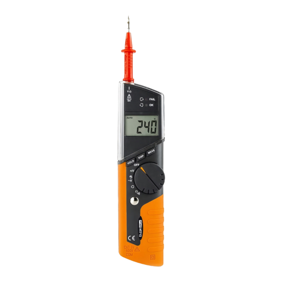
HT712 4. OPERATING INSTRUCTIONS 4.1. INSTRUMENT - DESCRIPTION 4.1.1. Front panel LEGEND: 1. Test probe (accessory) 2. V+/Ω input terminal 3. DISP key 4. HOLD key 5. Metallic pad 6. COM input terminal 7. Rotary selector Fig. 1: Instrument description 8. -
Page 8: Measurements - Description
HT712 4.4. MEASUREMENTS - DESCRIPTION 4.4.1. DC voltage measurement CAUTION The maximum input for DC voltage is 600V. Don’t try to measure higher voltages to avoid risks of electrical shocks or serious damages to the instrument. 1. Turn the selector on 2. -
Page 9: Ac Voltage And Frequency Measurement With 2 Test Leads
HT712 4.4.2. AC voltage and frequency measurement with 2 test leads CAUTION The maximum input for AC voltage is 600V. Don’t try to measure higher voltages to avoid risks of electrical shocks or serious damages to the instrument. 1. Turn the selector on 2. -
Page 10: Ac Voltage And Frequency Measurement With 1 Test Leads
HT712 4.4.3. AC voltage and frequency measurement with 1 test leads CAUTION The maximum input for AC voltage is 600V. Don’t try to measure higher voltages to avoid risks of electrical shocks or serious damages to the instrument. 1. Turn the selector on 2. -
Page 11: Phase Sequence Test And Phase Conformity Test
HT712 4.4.4. Phase sequence test and phase conformity test CAUTION The maximum input for AC voltage is 600V. Don’t try to measure higher voltages to avoid risks of electrical shocks or serious damages to the instrument. 1. Turn the selector on 2. - Page 12 HT712 8. Disconnect the test probe to the L1 phase cable (at this point the “PH” disappears). The symbol " " means that the instrument is waiting for the second phase to be measured. For the phase rotation test: 9. Connect the test probe to the L2 phase cable or simply lean it to the insulated cable under test.
-
Page 13: Resistance Measurement And Continuity Test
HT712 4.4.5. Resistance measurement and continuity test CAUTION Before taking in circuit resistance measurements, remove power from the circuit being tested and discharge all capacitors. 1. Turn the selector on 2. Insert the black test lead in the COM jack and the red probe in the V+/Ω... -
Page 14: Maintenance
HT712 5. MAINTENANCE 5.1. GENERAL INFORMATION This is a precision instrument. To guarantee its performances be sure to use it or keep it stored on suitable environmental conditions. Do not expose it to high temperatures or humidity or direct sunlight. Be sure to turn it off after use. If you expect not to use the instrument for a long period remove batteries to avoid leakages of battery liquid which could damage the its inner components. -
Page 15: Technical Specifications
HT712 6. TECHNICAL SPECIFICATIONS 6.1. TECHNICAL FEATURES The accuracy is indicated as [% of reading + number of digits]. It is referred to the following environmental conditions: temperature 23°C ± 5°C, relative humidity < 70%. DC voltage measurement Protection against... -
Page 16: Electrical
HT712 6.1.1. Electrical Conversion TRMS Display refreshing rate 3 times per second 6.1.2. Safety The instrument complies with EN 61010-1 Insulation Class 2, Double insulation Pollution degree Overvoltage category CAT IV 600 V For inside use, max height 2000m; 6561ft 6.1.3. -
Page 17: Service
HT712 7. SERVICE 7.1. WARRANTY CONDITIONS This instrument is guaranteed for one year against material or production defects, in accordance with our general sales conditions. During the warranty period the manufacturer reserves the right to decide either to repair or replace the product.
Need help?
Do you have a question about the HT712 and is the answer not in the manual?
Questions and answers