
Related Manuals for HT HT4011


Summary of Contents for HT HT4011
- Page 1 ENGLISH User manual GlobalTestSupply www. .com Find Quality Products Online at: sales@GlobalTestSupply.com Copyright HT ITALIA 2014 Release EN 1.01 - 21/02/2014...
-
Page 2: Table Of Contents
HT4011 Table of contents: PRECAUTIONS AND SAFETY MEASURES ............... 2 1.1. Preliminary instructions ..................... 2 1.2. During use ......................... 3 1.3. After use ..........................3 1.4. Definition of measurement (overvoltage) category ............3 GENERAL DESCRIPTION ................... 4 ... -
Page 3: Precautions And Safety Measures
HT4011 1. PRECAUTIONS AND SAFETY MEASURES The instrument has been designed in compliance with directive IEC/EN61010-1 relevant to electronic measuring instruments. For your safety and in order to prevent damaging the instrument, please carefully follow the procedures described in this manual and read all notes preceded by the symbol with the utmost attention. -
Page 4: During Use
HT4011 1.2. DURING USE Please carefully read the following recommendations and instructions: CAUTION Failure to comply with the Caution notes may damage the instrument and/or its components or be a source of danger for the operator. Before activating the switch, remove the conductor from the clamp jaw or disconnect the test leads from the circuit under test. -
Page 5: General Description
HT4011 2. GENERAL DESCRIPTION The instrument carries out the following measurements: DC and AC voltage up to 600V AC current up to 400A Resistance and continuity test with buzzer Capacitance Frequency with leads Duty Cycle ... -
Page 6: Preparation For Use
HT4011 3. PREPARATION FOR USE 3.1. INITIAL CHECKS Before shipping, the instrument has been checked from an electric as well as mechanical point of view. All possible precautions have been taken so that the instrument is delivered undamaged. However, we recommend generally checking the instrument in order to detect possible damage suffered during transport. -
Page 7: Operating Instructions
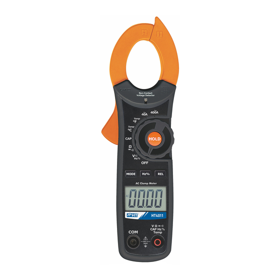
HT4011 4. OPERATING INSTRUCTIONS 4.1. INSTRUMENT DESCRIPTION 4.1.1. Description of the controls CAPTION: 1. Inductive clamp jaw 2. AC voltage detector 3. Rotary selector switch 4. Jaw trigger 5. HOLD key 6. MODE key 7. REL key 8. Hz% key 9. -
Page 8: Description Of Function Keys
HT4011 4.2. DESCRIPTION OF FUNCTION KEYS 4.2.1. HOLD key Short pressing the “HOLD” key activates the function Data HOLD, i.e. the value of the measured quantity is frozen. The message “HOLD” appears on the display. This operating mode is disabled when the “HOLD” key is pressed again or the switch is operated. -
Page 9: Description Of Rotary Switch Functions
HT4011 4.3. DESCRIPTION OF ROTARY SWITCH FUNCTIONS 4.3.1. DC voltage measurement CAUTION The maximum input DC voltage is 600Vrms. Do not measure voltages exceeding the limits given in this manual. Exceeding these limits could result in electrical shocks to the user and damage to the instrument. -
Page 10: Ac Voltage Measurement
HT4011 4.3.2. AC voltage measurement CAUTION The maximum input AC voltage is 600V. Do not measure voltages exceeding the limits given in this manual. Exceeding these limits could result in electrical shocks to the user and damage to the instrument. -
Page 11: Frequency And Duty Cycle Measurement
HT4011 4.3.3. Frequency and Duty Cycle measurement CAUTION When measuring frequency with leads, the maximum input AC voltage is 600Vrms. Do not measure voltages exceeding the limits given in this manual. Exceeding these limits could result in electrical shocks to the user and damage to the instrument. -
Page 12: Resistance Measurement
HT4011 4.3.4. Resistance measurement CAUTION Before attempting any resistance measurement, remove power from the circuit under test and discharge all capacitors, if present. Fig. 5: Use of the clamp for Resistance measurement 1. Select the position 2. Insert the red cable into input terminal V... -
Page 13: Capacitance Measurement
HT4011 4.3.5. Capacitance measurement CAUTION Before carrying out capacitance measurements on circuits or capacitors, cut off power supply from the circuit being tested and let all capacitance in it be discharged. Fig. 6: Use of the clamp for capacitance measurement 1. -
Page 14: Continuity Test And Diode Test
HT4011 4.3.6. Continuity test and diode test CAUTION Before attempting any resistance measurement, remove power from the circuit under test and discharge all capacitors, if present. Fig. 7: Use of the clamp for continuity test and diode test 1. Select the position ... -
Page 15: Temperature Measurement In °C And °F
HT4011 4.3.7. Temperature measurement in °C and °F CAUTION Do not put the temperature probe into contact with live surfaces. Voltages higher than 30Vrms or 60VDC imply electrical shock hazard. Fig. 8: Use of the clamp for temperature measurement 1. Select the Temp°C or Temp°F position. -
Page 16: Ac Current Measurement
HT4011 4.3.8. AC current measurement CAUTION Before attempting any measurement disconnect all the test leads from the circuit under test and from the meter's input terminals. Fig. 9: Use of the clamp for AC current measurement 1. Select position 40A or 400A 2. -
Page 17: Maintenance
HT4011 5. MAINTENANCE 5.1. GENERAL INFORMATION 1. The instrument you purchased is a precision instrument. While using and storing the instrument, carefully observe the recommendations listed in this manual in order to prevent possible damage or danger during use. 2. Do not use the instrument in environments with high humidity levels or high temperatures. -
Page 18: Technical Specifications
HT4011 6. TECHNICAL SPECIFICATIONS 6.1. TECHNICAL CHARACTERISTICS Accuracy is calculated as ± [% reading + (number of digits) x resolution]. It is referred to a temperature 18°C 28°C with relative humidity <75% RH. AC Voltage (Autorange) Input Overvoltage Range... -
Page 19: Reference Standards
HT4011 Frequency with leads (Autorange) Range Resolution Accuracy Sensitivity Overvoltage protection 0.01Hz 10.00Hz 49.99Hz 0.1Hz 50.0Hz 499.9Hz 600VDC/ACrms (1.5%rdg+2digits) 15Vrms 0,001kHz 0.500kHz 4.999kHz 0.01kHz 5.00kHz 10.0kHz Duty cycle (Autorange) Range Resolution Accuracy ... -
Page 20: Accessories Provided
HT4011 6.3. ACCESSORIES PROVIDED Pair of 2mm test leads Adapter + K-type wire probe Carrying bag Batteries (not fitted) User manual 6.4. OPTIONAL ACCESSORIES Probe Temperature Accuracy Probe Model Description diameter range length (mm) (at 100°C) (mm) -40 ... -
Page 21: Service
HT4011 7. SERVICE 7.1. WARRANTY CONDITIONS This instrument is warranted against any material or manufacturing defect, in compliance with the general sales conditions. During the warranty period, defective parts may be replaced. However, the manufacturer reserves the right to repair or replace the product.
Need help?
Do you have a question about the HT4011 and is the answer not in the manual?
Questions and answers