Table of Contents
Advertisement
Quick Links
KT5500
5-1/2" (13.97cm) 18.7K Lbs.-Ft.
Hydraulic Power Tong & CLINCHER® Backup
• Specifications
• Operation
• Maintenance
• Assembly
©2011 McCoy Corporation. All rights reserved.
Published by McCoy Corporation, Technical Publications Department
14755 - 121A Avenue • Edmonton, AB, Canada, T5L 2T2
Model 80-0422
mccoyglobal.com
TECHNICAL MANUAL
Model 80-0421-3
Advertisement
Table of Contents

Related Manuals for Farr KT5500

Summary of Contents for Farr KT5500
-
Page 1: Specifications
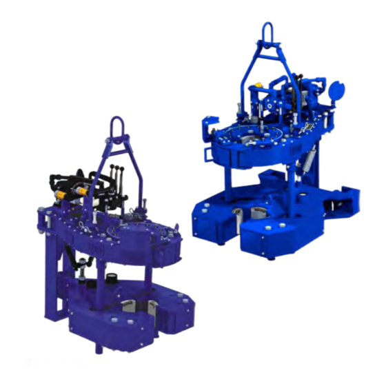
TECHNICAL MANUAL KT5500 5-1/2” (13.97cm) 18.7K Lbs.-Ft. Model 80-0421-3 Hydraulic Power Tong & CLINCHER® Backup • Specifications • Operation • Maintenance • Assembly Model 80-0422 mccoyglobal.com ©2011 McCoy Corporation. All rights reserved. Published by McCoy Corporation, Technical Publications Department 14755 - 121A Avenue • Edmonton, AB, Canada, T5L 2T2... - Page 3 KT5500 5- ” T & CLInCHER® B aCKup This manual covers the following models: DESCRIpTIon oVERaLL Tong BaCKup MoDEL MoDEL MoDEL 5-1/2” configured power tong & low-profile compression load cell-style CLINCHER® backup. Tong equipped with hydraulic motor control, lift 80-0420-16 80-0420-3 85-0408 control, backup control, rigid sling, & and safety door system. 5-1/2” configured power tong & tension load cell-style CLINCHER® backup. Tong equipped with hydraulic motor control, lift control, backup 80-0421-3 80-0420-3 85-0506 control, rigid sling, & and safety door system.
- Page 4 This page intentionally left blank...
- Page 5 KT5500 5- ” T & CLInCHER® B aCKup WARNINGS A “LOAD-BEARING DEVICE” IS A CHAIN SLING, RIGID SLING, SPREADER BAR ASSEMBLY, FRAME, OR ANY OTHER DEVICE THAT BEARS THE PARTIAL OR TOTAL WEIGHT OF THE EQUIPMENT FOR WHICH THIS MANUAL HAS BEEN PRODUCED THE LOAD-BEARING DEVICE SUPPLIED BY MCCOY DRILLING &...
- Page 6 This page intentionally left blank...
-
Page 7: Support Roller
KT5500 5- ” T & CLInCHER® B aCKup Copyright © 2007 - 2011 McCoy Corporation, including its wholly owned subsidiaries, (“McCoy”), all rights reserved. This document is the property of McCoy and is supplied as reference information for users of our products. This document and the contents within are consid- ered confidential information, not to be disclosed, copied, transmitted, transcribed in any form, or stored on any type of data storage media without the express written consent of McCoy. McCoy has made every effort to ensure the information contained in this document is accurate and current. This manual is intended to provide equipment operation and safety instructions for your equipment. However, McCoy does not warrant or guarantee that the informa- tion is either complete or accurate in every respect and the user of the manual should consult with its McCoy sales representative for any clarifications and updates. The user of the manual shall protect, indemnify, and hold harmless McCoy and its directors, officers, employees, and agents from and against all liability for personal injury, death, or property damage resulting directly or indirectly from the use of the information contained in this manual. Observance of all descriptions, information and instructions set out in this manual is the full responsibility of the user. This manual is intended for guidance and informational purposes and must be used in association with adequate training and on-the-job supervision to provide safe and effective equipment use. It is the responsibility of the user to conform to all regulations and requirements issued by an authority or agency which may affect the operation, safety or equipment integrity, that may overrule the content of this documentation. The user will acknowledge and obey any general legal or other mandatory regulation in force relating to accident prevention, safety, and equipment integrity. Summary Of Revisions Date Section Page Description Of Revision Sep 2007 Initial Release Corrected table of assemblies covered by this manual, added compression LC style Intro backup... -
Page 8: Table Of Contents
KT5500 5- ” T & CLInCHER® B aCKup Introduction ................................. Section 1 Introduction & Contact Information ........................ 1.1 Equipment Specifications ............................. 1.2 Lubricant Specifications ............................ 1.4 Setup & Operation ..............................Section 2 Sling / Load-Bearing Device Safety ........................ 2.1 Major Component Identification .......................... 2.4 Hydraulic Schematic / Component Identification .................... 2.8 Hydraulic Connections ............................ 2.11 Tong & Backup Jaw Availability & Installation . - Page 9 The information presented in this document will provide setup, operating, and maintenance instruc- tions for your KT5500 tong & CLINCHER® backup. Due to the wide variety of operating conditions, these instructions must be considered guidelines rather than absolute operating procedures. It is the responsibility of the user to use these guidelines together with an experienced manager to develop operating procedures that conform to all policies set forth by the operating authority (ies).
- Page 10 This page intentionally left blank...
- Page 11 KT5500 5- ” T & CLInCHER® B nTRoDuCTIon aCKup Congratulations on the purchase of your FARR® KT-5500 5-1/2” tong and CLINCHER® backup. This unit will provide you with years of outstanding performance. Simple maintenance and care will extend its life and ensure years of excellent performance and reliability. The setup, operating, and maintenance instructions in this manual will assist you in giving your equipment the care it requires. Please carefully read the manual before installing and using your equipment. Replace- ment parts are readily available from McCoy Drilling & Completions | FARR in Edmonton Alberta. Note that many parts are transferable between FARR® tongs and backups. Should you need replacement parts, or should you experience any difficulty not covered in this manual, please contact: McCoy Drilling & Completions | FARR 14755 121A Avenue Edmonton, Alberta Canada T5L 2T2 Phone: 780.453.3277 Fax: 780.455.2432 Sales Fax: 780.481.9246 Email Engineering: engFarr@mccoyglobal.com Email Sales: salesFarr@mccoyglobal.com Customer Care: customerCareFarr@mccoyglobal.com Website: http://www.mccoyglobal.com/index.php/drilling-completions Model 80-0421-3 Shown ECHnICaL anuaL ECTIon onTEnTS...
- Page 12 KT5500 5- ” T & CLInCHER® B aCKup pECIfICaTIonS Model 80-0421-3 Shown 52” ECTIon onTEnTS ECHnICaL anuaL...
- Page 13 KT5500 5- ” T & CLInCHER® B pECIfICaTIonS aCKup Torque Table ** pressure high gear low gear psi / Mpa lbs.-ft. lbs.-ft. 1000 / 6.89 1530 2074 7650 10372 1400 / 9.66 2250 3050 11250 15253 1800 / 12.41 2970...
- Page 14 KT5500 5- ” T & CLInCHER® B aCKup pECIfICaTIonS Use an EP synthetic grease that meets or exceeds the following specifications: Thickener Lithium Complex NLGI consistency grade 2 NLGI performance grade GC-LB Penetration - ASTM D 217 (25°C [77°F] 265-295 minimum 0.1 mm) worked 60 strokes Dropping point, °F[°C] - ASTM D2265 550 [288] minimum High temperature life, hours - ASTM D 3527 160 minimum Oxidation stability, psi - ASTM D 942 (100 hr/300 hr) 0/3 Water washout, percent - ASTM D 1264 1.8 max Rust and corrosion - ASTM D 1743 pass Oil separation, percent loss - ASTM D 1742 1.1 max (24 hours, 25°C [77°F] Leakage, g lost - ASTM D 4290 1.0 max...
-
Page 15: Sling / Load-Bearing Device Safety
BLY, FRAME, OR ANY OTHER DEVICE THAT BEARS THE PARTIAL OR TOTAL WEIGHT OF THE EQUIPMENT DESCRIBED IN THIS MANUAL) HAS BEEN SPECIFIED OR DESIGNED TO SUPPORT THE EQUIPMENT DESCRIBED IN THIS DOCUMENT. FARR WILL NOT GUARANTEE THE ABILITY OF THE LOAD-BEARING DEVICE TO SUPPORT ANY OTHER PART, ASSEMBLY OR COMBINA-... - Page 16 KT5500 5- ” T & CLInCHER® B & o aCKup ETup pERaTIon Inspection Of Slings McCoy Drilling & Completions strongly recommends the following practices: A complete inspection of new load-bearing devices and attachments shall be performed by a qualified, designated person prior to initial use. Each link and component shall be examined individually, taking care to expose and examine all surfaces including the inner link surface. The sling shall be examined for conditions such as those listed in the removal criteria below. In addition, daily inspection of slings, fastenings and attachments shall be performed by a designated person. If damage or defects are found at either inspection, the damaged or defective component shall be quarantined from service until it can be properly repaired or replaced. Removal Criteria: A load-bearing device shall be removed from service if conditions such as the following are present: • Missing or illegible sling identification. • Cracks or breaks • Evidence of tampering is seen - sling tag has been modified or obscured, or tamper-proof nuts are missing. • Signs of impact on load-bearing components, including spreader bars, lifting lugs, rigid slings & rigid sling weldments, and legs & leg mounts.
- Page 17 Storage Of Load-Bearing Devices Proper storage of out-of-service load bearing devices is important to ensure full integrity of the device once it is returned to service. Farr recommends observing the following practices. • Wipe off all excess grease. Use a solvent-based cleaner on rags to wipe all external surfaces to remove residual grease or hydraulic fluid. Once the outside surfaces have been de-greased, wipe all external surfaces with clean water to remove residual solvent. • Farr recommends that an anti-corrosive agent such as Tectyl ® 506 be applied to all external surfaces. Refer to manufac- turer data sheets for proper application and safety information. Allow the anti-corrosive coating ample time to dry - refer to manufacturer data sheets for drying times at room temperature. • Store in a clean, dry location. When returning to service, note that a full inspection of the device must be performed. ECHnICaL anuaL...
-
Page 18: Major Component Identification
KT5500 5- ” T & CLInCHER® B & o aCKup ETup pERaTIon MAJOR COMPONENT IDENTIFICATION Item Description Front Leg Assembly Rigid Sling Power Tong Rear Backup Spring Support Assembly Rear Leg Assembly - Tension Load Cell Configuration CLINCHER® Backup - Tension Load Cell Configuration ECTIon onTEnTS ECHnICaL anuaL... - Page 19 & o KT5500 5- ” T & CLInCHER® B ETup pERaTIon aCKup Item Description Rigid Sling Leveling Device Cage Plate Assembly Safety Door Switch Guard Safety Door Switch Tong Door Latch Torque Gauge Mounting Plate Backing Pin Assembly Tong Jaws with Die Inserts Brake Band Adjustment Tong Door Cylinder Tong Door Weldment ECHnICaL anuaL ECTIon onTEnTS...
- Page 20 KT5500 5- ” T & CLInCHER® B & o aCKup ETup pERaTIon Item Description Hydraulic Valve Bank Assembly Manual Shift Assembly Access Panel CLINCHER® Cylinder With Wraparound Insert Hydraulic Motor Motor Mount Tension Load Cell ECTIon onTEnTS ECHnICaL anuaL...
- Page 21 & o KT5500 5- ” T & CLInCHER® B ETup pERaTIon aCKup Item Description CLINCHER® Backup - Compression Load Cell Configuration Rear Leg Assembly - Compression Load Cell Configuration Compression Load Cell ECHnICaL anuaL ECTIon onTEnTS...
-
Page 22: Hydraulic Schematic / Component Identification
KT5500 5- ” T & CLInCHER® B & o aCKup ETup pERaTIon HYDRAULIC SCHEMATIC / COMPONENT IDENTIFICATION Your tong may be equipped with one or two control valves, as well as safety door switch and hydraulics, depending upon the specific model. Disregard the control valves indicated on the following schematics that do not apply to your model. - Page 23 & o KT5500 5- ” T & CLInCHER® B ETup pERaTIon aCKup ECHnICaL anuaL ECTIon onTEnTS...
- Page 24 KT5500 5- ” T & CLInCHER® B & o aCKup ETup pERaTIon 2.10 ECTIon onTEnTS ECHnICaL anuaL...
-
Page 25: Hydraulic Connections
& o KT5500 5- ” T & CLInCHER® B ETup pERaTIon aCKup HYDRAULIC CONNECTIONS A pair of hydraulic lines - a 1” supply line and a 1-1/4” return line - connect the tong to the power unit (see illustration below). Ancillary devices (hydraulic motors, hydraulic cylinders, etc.) are connected through the valve block. Perform any hydraulic connection when the power unit is not running, or when the hydraulic pump is disengaged. The possibility of error in inter-changing the high pressure supply hose and the low pressure return hose has been eliminated, because the supply side coupling is smaller than the return side. Hydraulic Supply (1”) Hydraulic Return (1-1/4”) 2.11 ECHnICaL anuaL ECTIon onTEnTS... - Page 26 The following table lists all jaw die kits that are available as standard stocked sizes for this model of tong. McCoy Drilling & Completions | Farr offers a good selection of standard jaw sizes. However, please note that we can custom-engineer and manufacture any size of jaw within the range of the tong. Jaw systems are available to allow use of die inserts intended for...
- Page 27 KT5500 5- ” T & CLInCHER® B aCKup WRAPAROUND JAW DIE KITS (Inserts Not Included) Description Part Number 2-3/8” - 3-1/2” Wraparound Jaw Die Kit 1064-WJK-350 4” - 5-1/2” Wraparound Jaw Die Kit 1064-WJK-550 2-3/8” Wraparound Insert (for use in 1064-WJK-350) 12-2001 2-7/8” Wraparound Insert (for use in 1064-WJK-350) 12-2003 3-1/2” Wraparound Insert (for use in 1064-WJK-350) 12-2006 4” Wraparound Insert (for use in 1064-WJK-350) 12-2007 4-1/2” Wraparound Insert (for use in 1064-WJK-550) 12-2009 5” Wraparound Insert (for use in 1064-WJK-550) 12-2011 5-1/2” Wraparound Insert (for use in 1064-WJK-550) 12-2012 Jaw / Jaw Die Removal The tong jaws will often require removal to change jaw size or replace worn jaw die inserts. Support the jaw being removed...
- Page 28 KT5500 5- ” T & CLInCHER® B aCKup Jaw / Jaw Die Removal (continued): Backup Jaw Availability The following table lists all inserts that are available as standard sizes for the 5-1/2” CLINCHER® backup. If your desired size is not listed, Farr can engineer custom jaw sizes - contact sales for further information. 3.75” CLINCHER® Backup Insert 12-6034 Description Part Number 2.375” CLINCHER® Backup Insert 12-6003 3.875” CLINCHER® Backup Insert 12-6118 2.375” CLINCHER® Backup Aluminum Insert 12-6120 4” CLINCHER® Backup Insert 12-6043 2.875” CLINCHER® Backup Insert 12-6007 4” CLINCHER® Backup Aluminum Insert 12-6130 2.875” CLINCHER® Backup Aluminum Insert 12-6113 4.125” CLINCHER® Backup Insert 12-6046 2.875” CLINCHER® Backup Insert (Grit)
- Page 29 & o KT5500 5- ” T & CLInCHER® B ETup pERaTIon aCKup CLINCHER® Backup Jaw Removal/Installation Extend CLINCHER® cylinders enough so that the hex flat-head cap screws securing the die retainer tabs are well exposed. Turn off hydraulic power. ii. Remove the two hex flat-head cap screws securing the die retainer tab on the top of the CLINCHER® die. iii. Remove the top die retainer tabs. iv. Slide the die straight up, and remove.
-
Page 30: Tong Rig-Up & Leveling
KT5500 5- ” T & CLInCHER® B & o aCKup ETup pERaTIon To remove the die from the rear jaw, ensure both cylinders are retracted. Remove the hex bolt securing the rear jaw assembly, then slide rear jaw forward enough so that the flat-head cap screws securing the die retainer tab is well exposed. Remove the die following the same procedures as for the CLINCHER® cylinders. Reverse this procedure to install or replace jaws. TONG RIG-UP & LEVELING Suspension & Restraint Suspend the tong and backup from a location as near to the centre of the drill rotary as possible, and from a location high enough on the mast to ensure easy handling. The lower the point from which the tong is suspended, the more effort will be... - Page 31 & o KT5500 5- ” T & CLInCHER® B ETup pERaTIon aCKup Suspension & Restraint (continued): McCoy Drilling & Completions recommends using dual backup (snub) lines of sufficient strength to withstand the force imparted by the maximum rated torque of the tong and backup assembly in use. The snub lines will arrest uncontrolled movement of the tong and backup in the event slipping of the backup jaws. Calculate the force on the snub lines by dividing the maximum torque of the tong by the tong’s torque arm (expressed in feet). For example, a 25,000 lbs.-ft. tong with a 32 inch (2.667 ft.) torque arm will generate 9375 lbs. of force against the snub line. Select your snub lines based upon the total force and the margins of safety dictated by the policies of your company and by established engineering practices. Ultimately, calculating the force on the snub line and selection of the snub line is the complete responsibility of the customer. Snub lines must be securely connected to the rear of the tong and backup assembly, and tied off to a suitable anchor. MCCOY DRILLING & COMPLETIONS ACCEPTS NO RESPONSIBILITY FOR DESIGNING AND SELECTING AN ADEQUATE SUSPENSION AND RESTRAINT SYSTEM FOR YOUR DRILLING EQUIPMENT ALL SELECTED FASTENERS, SHACKLES, CLAMPS, ETC.
- Page 32 KT5500 5- ” T & CLInCHER® B & o aCKup ETup pERaTIon Tong Leveling Continued: ii. Place a level lengthwise (front to back) along the tong, ensuring that it is parallel with the surface of the tong. Loosen the 3/4” jam nuts on the adjusting bolts on rigid sling brackets. Completely loosen the adjusting bolts. Turn each adjusting bolt equally until tong hangs level front-to-back. Lock adjusting bolts in place with the jam nuts. Loosen 3/4” hex jam nut be- fore rotating adjustment bolt Compression Load Cell Configuration The backup is directly coupled to the compression load cell via the backup body paddle. The load cell hanger is simply hung on the paddle and secured through the top of the “U” by a bolt and washer set, and in normal operation does not need to be adjusted or removed. The assembly in the first of the following two illustrations has been configured in the “make-up” configura- tion; to convert the assembly to the “break-out” configuration remove the bolt and washer set securing the load cell holder to the paddle, and move the entire assembly to the other side of the paddle. Load cell configured for make-up operations 2.18...
- Page 33 & o KT5500 5- ” T & CLInCHER® B ETup pERaTIon aCKup Compression Load Cell Configuration (continued): Load cell configured for break-out operations Tension Load Cell Configuration The backup is coupled to the rear leg of the assembly with a tension load cell on one side, and a restraint chain on the other. To change the torque measurement configuration (make up to break out or visa versa) simply remove the heavy duty bolts securing the load cell and restraint chains, and switch to the opposite sides. Reinstall the heavy duty bolts to secure the load...
- Page 34 This page intentionally left blank...
-
Page 35: Tong Operation
& o KT5500 5- ” T & CLInCHER® B ETup pERaTIon aCKup TONG OPERATION Operator Training Many companies set qualification standards that must be met before equipment is may be operated without supervision. McCoy Drilling & Completions recommends operator training, which typically consists of operation of the equipment under the supervi- sion of a trained equipment operator until a satisfactory level of competence is achieved. Typical operator training should include: • Introduction to and general description of equipment • Technical specifications and performance data • Operating instructions • Control systems and interlocks • Operating hazards • Checks and inspections Initial Start-up and Break-in Procedure YOUR EQUIPMENT HAS BEEN THOROUGHLY TESTED AND INSPECTED AT THE FACTORY. - Page 36 KT5500 5- ” T & CLInCHER® B & o aCKup ETup pERaTIon Valve Operation 4-way proportional valves control operation of hydraulic devices on the tong assembly such as hydraulic motors and cylinders. When any one valve is “centered” or in the detent position, there is no hydraulic output from the valve. When the valve is pushed forward there is an effect, and when the valve is pulled back, there is an opposite effect. These valves feature proportional con- trol, which means that further extension of the valve handle (thereby further opening the valve orifice) results in proportionally higher hydraulic output to the controlled device. The following illustration demonstrates the type and effect of the hydraulic valves with which this tong is may be equipped. TONG MOTOR This is a proportional valve. Pushing the valve handle forward will cause the tong motor to rotate in a clockwise direction (as seen from the top of the tong). This is the desired direction of rotation for making up a joint. Pulling the valve handle in the opposite direction results in counter-clockwise rotation, which is the desired direction of rotation for breaking out a joint. BACKUP Depending on the type of backup with which your system is equipped (Wedge, Clincher, or Hydraulic) pushing forward on this valve will extend the backup cylinder (s), or actuate a sequence valve. Pulling backward, towards the operator, reverses the action. 2.22 ECTIon onTEnTS ECHnICaL anuaL...
- Page 37 & o KT5500 5- ” T & CLInCHER® B ETup pERaTIon aCKup LIFT CYLINDER This is a direct-acting valve. Pushing the valve handle forward will cause the lift cylinder to lift the tong vertically. Pulling the valve handle in the opposite direction will cause the lift cylinder to lower the tong. SHIFTING GEARS The shifting shaft has three “detent” positions identifying the low speed/high torque position, the “neutral” or free-spinning posi- tion, and the high speed/low torque position. The detent strength may be adjusted by releasing the locknut on the detent tube and increasing or relaxing pressure on the detent spring. Ensure the locknut is tightened once the desired detent pressure has been set. To shift to the high-speed gear, move the shifting handle upward from neutral position. To shift to the low-speed gear, move the shifting handle down through the neutral detent to its lowest position. Note that the high clutch gear or the low clutch gear may not be exactly aligned when shifting, so the operator may need to “bump” the motor control handle slightly to turn the main clutch gear shaft and shifting collar into alignment. This is most effective when applying a small amount of pressure on the gear shift lever in the direction you want to shift the tong, ensuring the shifting collar will “catch” when the main clutch gear aligns with either the high or low clutch gear. SHIFTING TONG WHILE ROTATING THE MOTOR AND CAGE PLATE MAY RESULT IN CATASTROPHIC GEAR TRAIN FAILURE 2.23...
-
Page 38: Extreme Cold Weather Operation Procedures
KT5500 5- ” T & CLInCHER® B & o aCKup ETup pERaTIon GENERAL COMMENTS Position rotary gear in contact with both idler gears when breaking out joints or collars where high torques are required. When making-up integral (shouldered) joints, it is essential to make up the last turn of the threads in low gear. This reduces the tendency of an instant stop or a sudden increase in torque, which induces extremely high stresses on the gear train. DO NOT employ the “snap break” method of breaking-out joints when pulling a string. By definition, the “snap break” method is a procedure used by some operators to break out connections, accomplished by leaving slack in the “jaw-pipe” engagement, and then quickly pulling the throttle valve control lever allowing the tong to snap into its loaded or high torque condition. Although this method is very effective in breaking out joints, the extremely high stress placed on the gear train frequently causes gear breakage. -
Page 39: General Maintenance Safety Practices
KT5500 5- ” T & CLInCHER® B aInTEnanCE aCKup McCoy Drilling & Completions recognizes that minor on-site repairs and modifications are required to maintain peak operating condition of your equipment, or to match your equipment with the operating environment. Examples of minor repairs are • replacement of damaged hydraulic hoses and fittings. • replacement of malfunctioning pressure gauges and valves. • replacement of door cylinders • replacement of fasteners Any replaced component must be an identical component supplied by McCoy Drilling & Completions. Replaced fasteners must be Grade 8 or equivalent, or whatever fastener is specified by McCoy Drilling & Completions. GENERAL MAINTENANCE SAFETY PRACTICES The practices identified here are intended as a guideline. All personnel are responsible for performing their tasks in a manner that ensures worker, equipment, and environmental safety, and may require taking additional steps that are not identified in this section. Equipment maintenance shall be performed only by designated qualified maintenance personnel. Wear approved eye wear and footwear, and follow all of your company’s safety guidelines Do not begin a maintenance task without the proper tools or materials... -
Page 40: Lubrication
KT5500 5- ” T & CLInCHER® B aCKup aInTEnanCE LUBRICATION Use a quality multipurpose bearing lubricant that will remain within its viscosity range at expected operating temperatures. In addition, Farr recommends the following lubrication procedure at the completion of each job prior to storage. Cage Plate Cam Followers Apply grease to the grease fittings recessed in both the top and bottom cage plates (26 locations total - 13 top / 13 bottom). Support Rollers Apply grease to the support roller bearings through the grease fittings recessed into the top of each support roller shaft. NOTE: the safety door cam assembly needs to be removed to access the grease fitting in the top of the door pivot roller shaft (ten locations total). ECTIon onTEnTS ECHnICaL anuaL... -
Page 41: Rotary Idler
KT5500 5- ” T & CLInCHER® B aInTEnanCE aCKup Rotary Idlers Apply grease to the rotary idler bearings through the grease fittings recessed into the top of each shaft on the top face of the tong (two locations total). Pinion Idler Apply grease to the pinion idler bearing through the grease fitting recessed into the top of the half-shaft, located on the bottom face of the tong (one location only). ECHnICaL anuaL ECTIon onTEnTS... - Page 42 KT5500 5- ” T & CLInCHER® B aCKup aInTEnanCE Pinion Apply grease to the pinion bearings through the grease fittings located on the bearing caps on the top and bottom faces of the tong (two locations top, two locations bottom). Clutch Bearings Apply grease to the clutch bearings through the two grease fittings located on the clutch bearing cap on the bottom face of the tong, and the single grease fitting recessed into the end of the clutch shaft. (three locations total). ECTIon onTEnTS ECHnICaL anuaL...
- Page 43 KT5500 5- ” T & CLInCHER® B aInTEnanCE aCKup Motor Mount Apply grease to the motor gear/clutch drive gear through the grease fitting located on the top of the motor mount (one location only). Shifting Shaft Apply grease to the shifting shaft and top shifting shaft bushing. The shaft and shifting yoke can be accessed through the cover plate on the side of the tong. Access shifter components through this panel ECHnICaL anuaL ECTIon onTEnTS...
- Page 44 KT5500 5- ” T & CLInCHER® B aCKup aInTEnanCE Door Latch Apply grease to the door latch through the grease fitting located in the top of the adjustment cam. 10. CLINCHER® Cylinders Apply grease to the external surfaces of the clincher cylinders through the grease fittings in the top and bottom body plates (eight locations total). ECTIon onTEnTS ECHnICaL anuaL...
-
Page 45: Adjustments
KT5500 5- ” T & CLInCHER® B aInTEnanCE aCKup 11. Compression Load Cell (Compression Load Cell Style Backups Only) Apply grease to the flat surfaces of the compression load cell where contact is made with the rear leg and the paddle of the backup. pply A thin lAyer of greAse to these surfAces Farr recommends that a liberal coating of grease be applied to the cam surface of the rotary drive gear prior to jaw installation. Also, the clutch inspection plate should periodically be removed and a coating of grease applied to the clutch, drive gears and shifting shaft. ADJUSTMENTS Brake Band Tension Adjustment: The top and bottom brake bands must be periodically adjusted to continue to provide smooth and efficient jaw cam action. If the cage plate turns with the rotary gear, the jaws will not cam properly and, therefore, will not bite on the tubing or casing. - Page 46 KT5500 5- ” T & CLInCHER® B aCKup aInTEnanCE Door Latch Adjustment Normal operation of the tong may cause wear of the door latch, which will cause the door to develop a loose fit at the latch. A latch cam plate is located at the top face of the door. The cam plate has eight positioning holes located on a 360 degree bolt circle. The latch cam shaft extends down through the door and is secured at the top by a 3/8” hex head bolt. To make adjust- ments in door alignment, remove the 3/8” bolt and turn the cam with a wrench. When the door has been adequately aligned, replace the 3/8” bolt (see illustration next page). THE DOOR IS AN IMPORTANT PART OF THE STRUCTURAL INTEGRITY OF THE TONG. IT IS IMPERATIVE TO KEEP A SECURE FIT AT THE DOOR IN ORDER TO MAINTAIN PROPER GEAR ALIGNMENT, AND TO MINIMIZE THE POSSIBILITY OF DAMAGE TO THE GEAR TRAIN WHEN OPERATING THE TONG AT SPECIFIED TORQUE.
-
Page 47: Recommended Periodic Checks
KT5500 5- ” T & CLInCHER® B aInTEnanCE aCKup RECOMMENDED PERIODIC CHECKS Door Stop Spring The spring inside the actuator cylinder must be of sufficient strength to enable the door latch mechanism to snap closed prop- erly, and to hold the door in the open position when opened. Door stop spring fatigue will result in sluggish latch operation. Replace the latch spring inside the cylinder when this occurs. Backing Pin Perform a visual inspection of the backing pin after each job. Replace the pin if stress cracks or excessive wear is found, or if either pin is bent. Shifting Shaft The shifting yoke is secured to the shifting shaft by a locknut on the bottom of the yoke. Check locking nuts after each job. Do this by removing the clutch inspection plate and ensuring a snug fit prior to lubrication. Torque Gauge Assembly Periodic calibration of the torque gauge is recommended to assure accurate torque readings. When having the torque gauge serviced and calibrated, it is critical to note the arm length of the tong, as indicated in the “Specifications” section. Farr recom- mends that the torque gauge assembly be calibrated yearly. Periodically check to ensure the load cell is filled with oil (see Section 6). - Page 48 KT5500 5- ” T & CLInCHER® B aCKup aInTEnanCE 14. Remove door assembly by removing the door roller shaft. Support door assembly as the roller shaft is removed. Remove the nut from the top of the roller shaft, and use a soft alloy material (e.g. brass rod, etc.) to lightly tap the shaft down through the support roller assembly until it comes free at the bottom. Use caution that the threads on the ends of the support roller shafts are not damaged. Do not lose the door shoulder bushings. 15. Remove the hitch pin securing the torque gauge holder to the torque gauge mount weldment, and remove the mount. 16. Remove the four hex socket head cap screws securing the motor and the torque gauge mount weldment. Remove the torque gauge mount weldment, then lift the motor up and away from the motor mount. Inspect the motor gear, located at the bottom of the motor shaft, for gear clashing or tooth damage. Also, ensure that the motor gear is securely attached to the motor shaft. 17. Remove the cotter pin and clevis pin connecting the shifter handle to the shifter shaft (it is not necessary to disconnect the handle from the pivot lug weldment). 18. Unbolt the pivot lug weldment from the top plate, and remove the pivot lug and handle assembly. 19. Remove the four hex socket head cap screws securing the motor mount to the top plate. Use care not to dislodge and lose the two positioning dowels. 20. Remove the snap ring securing the drive gear to the top of the clutch shaft. Carefully remove the drive gear from the clutch shaft. 21. Remove the two 10-24 x 3/4” hex socket head cap screws securing the top clutch bearing retainer to the top plate. 22. Remove the top clutch bearing retainer, and bearing retainer spacer. The top clutch bearing and clutch bearing bushing may come off with the bearing retainer. 23. Pull the top bearing cap and spacer for the pinion drive gear by removing the four 1/2” bolts which secure the bearing cap.
-
Page 49: Assembly Procedures
& CLInCHER® B aInTEnanCE aCKup ASSEMBLY PROCEDURES Assembly of Farr Hydraulic Power Tongs is straightforward, and can be accomplished without the use of special tools. The instructions on this page are presented as a guide only, and are similar to the assembly sequence our technician would use while assembling the tong in our plant. ALL FASTENERS USED DURING REASSEMBLY OF LOAD-BEARING COMPONENTS (CHAIN SLINGS, RIGID SLINGS, BACKUP LEGS) MUST BE TIGHTENED TO THE CORRECT TORQUE. - Page 50 KT5500 5- ” T & CLInCHER® B aCKup aInTEnanCE NOTE ON INSTALLATION PRACTICES: Ensure all bearings are liberally greased before installing over a shaft or into gears or bearing caps. When inserting a shaft through a support roller assembly ensure shaft is greased. Also ensure all metal-to-metal contact in the gear train is adequately greased.
-
Page 51: Pinion Idler
KT5500 5- ” T & CLInCHER® B aInTEnanCE aCKup Mechanical Assembly Procedure (Continued): Install support roller assemblies in the locations exposed by the opening in the rotary gear. Continue to rotate the rotary gear, installing support roller assemblies in the rotary gear opening as it is rotated. Finish with the rotary gear aligned with the opening in the bottom plate. Press pinion bearing (PN 02-0007) into bottom pinion bearing cap (PN 997-D15-89), and install bearing cap into bottom plate of tong using four 1/2” UNC x 1-1/4” hex cap screws and four 1/2” lock washers. ASSEMBLY NOTE: Do not neglect to install the clutch bearing cap spacer (PN 1400-89A) between the bearing cap and the bottom plate of the tong. Press bottom clutch bearing (PN 02-0004) into clutch bearing cap (PN 997-D11-54), and install bearing cap into bottom plate of tong using four 3/8” UNC x 1-1/4” hex cap screwsand four lock washers. ASSEMBLY NOTE: Do not neglect to install the clutch bearing cap spacer (PN 1400-54A) between the bearing cap and the bottom plate of the tong. Install a retainer clip (PN 02-0009) into all three idler gears (PN 997-A2-119). Press an idler bearing (PN 02-0011) into each gear and secure with a second retainer clip. Lightly grease the larger circumference of the two rotary idler shafts (PN 997-D19-117) and slide them through two bearing and gear assemblies, centering the gear on the shaft. 10. Slide two bearing seals (PN 02-0010) over each end of the idler shafts and press against the retainer clips. See the exploded view of the rotary idler assembly on pp. 5.8 - 5.9 for correct orientation of the bearing seals. 11. Slide a bearing spacer (PN 997-D20-121) over each end of the rotary idler shafts. 12. Place each rotary idler assembly through the bottom plate, ensuring the ends of the shafts with the threaded holes for the grease fittings are pointed upward. 13. Place an idler pad (PN 1400-125) over the bottom side of each rotary idler shaft, and secure each with a 1-1/2” UNF nylock nut. 14. Place high pinion gear (PN 997-A4-87) shoulder side down over the lower bearing and bearing cap, centering as best as able. - Page 52 KT5500 5- ” T & CLInCHER® B aCKup Mechanical Assembly Procedure (Continued): 27. Secure the top plate with fourteen 3/8” UNC x 1-1/2” hex bolts and 3/8” lock washers, and five 3/8” UNC x 1” low-head height hex socket head cap screws. Do not install fasteners coincidental with the rigid sling brackets (shown circled in green) or the door cylinder post (shown circled in red). 28. Slide the clutch bearing retainer spacer (PN 1400-59A) over the bottom of the top clutch bearing retainer (PN 997-D11-59), and mount top clutch bearing retainer and spacer to the top plate with two #10-24 x 3/4” hex socket head cap screws. 29. Press top clutch bearing (PN 02-0002) into top clutch bearing retainer. Insert clutch bearing bushing (PN 997-60) shoulder side up between bearing and clutch shaft. 30. Secure clutch drive gear (PN 997-A3-61) to the top of the clutch shaft with retaining snap ring (PN 02-0001). 31. Install rotary idler pads (PN 997-D20-125) over the top of the rotary idler shafts and secure with 1-1/2” UNF hex nylock nuts. 32. Press remaining pinion bearing into the top pinion bearing cap (PN 997-D15-89) and secure over the top of the pinion gear shaft with four 1/2” UNC x 1-1/4” hex bolts and 1/2” lock washers. 33. Slide the top shifter bushing (PN 101-0020) over the shifting shaft and thread in to the top plate until snug. 34. Thread the detent tube (PN 101-0019) into the top shifter bushing as shown. Thread three 5/8” NC x 5/8” hex socket set screws into the remaining three ports in the top shifter bushing - do not bottom out the set screws on the shifting shaft, or the shaft will not move. 3.14 ECTIon onTEnTS ECHnICaL anuaL...
- Page 53 KT5500 5- ” T & CLInCHER® B aCKup Mechanical Assembly Procedure (Continued): 35. Insert the detent ball (PN 02-0018) through the end of the detent tube attached to the top shifter bushing, followed by the detent spring (PN 997-0-64) Thread a 7/16” UNF jam nut on to a 7/16” UNF x 1-1/4” hex bolt, and then thread the end of the bolt into the detent tube on the top shifter bushing. 36. Insert two 5/16” x 3/4” production ground dowel pins into the top plate, one on either side of the motor shaft and gear cut-out, directly behind the clutch assembly. 37. Position the motor mount (PN 1400-150) over the dowel pins and secure to the top plate using four 1/2” UNC x 2” hex socket head cap screws. 38. Insert a 5/16” x 5/16” x 1-1/2” square key into the key slot on the motor shaft. Secure the motor gear (PN 997-A10-149) to the hydraulic motor shaft using two 3/8” UNC x 3/8” flat point hex socket set screws. Ensure that the motor gear is oriented so that the machined end of the motor gear (the end in which the set screws are threaded) is flush with the end of the motor shaft. 39. Mount hydraulic motor (PN 87-0110) to motor mount. Secure the RH side of the motor (as seen from the back of the tong) with two 1/2” UNC x 1-1/4” hex socket head cap screws and 1/2” lock washers. The torque gauge holder weldment (PN 1500-09-04A) is secured by the two LH motor screws - position the torque gauge holder weldment in place, and secure it and the LH side of the motor with two 1/2” UNC x 1-1/2” hex socket head cap screws and 1/2” lock washers. 40. Attach the two #20 (1-1/4”) x JIC 1” flange elbows (PN 02-9216) to the motor ports using two #20 split flange kits (PN 02-9217). 41. Attach the shifter lug weldment (PN 101-0016) to the top plate of the tong next to the top shifter bushing weldment using four 3/8” UNC x 1-1/4” hex bolts and 3/8” lock washers. 42. Connect the shifter handle weldment’s (PN 1037-D-20B) pivot point to the pivot point of the shifter lug weldment using a 5/16” x 1-1/2” clevis pin. Connect the end of the shifter handle weldment to the top of the shifter shaft using a 5/16” x 1” clevis pin. Secure the clevis pins with .093” X 1.125” hitch pins.
- Page 54 KT5500 5- ” T & CLInCHER® B aCKup aInTEnanCE Mechanical Assembly Procedure (Continued): 44. Install the remaining support roller shafts (excluding the door pivot roller shaft): “Stand-Alone” Tongs (Models 80-0420-5, 80-0420-12) Slide a 7/8” narrow flat washer over the remaining five support roller shafts (PN 101-3942) and insert into the remaining support roller assemblies (excluding the door pivot support roller). ii. Secure the bottoms of the support roller shafts with 7/8” narrow flat washers and 7/8” UNF thin nylock nuts with the exception of the two shafts directly behind the brake band lug weldments. These two shafts will serve as leg mounts in...
- Page 55 KT5500 5- ” T & CLInCHER® B aInTEnanCE aCKup Mechanical Assembly Procedure (Continued): 55. Attach the door latch weldment (PN 1064-C7-15) to the door weldment (PN 1400-10) using the door latch cam (PN 1400-14) - ensure that the door latch springs (PN 997-16) are installed between the door latch and the door weldment. Thread the door latch cam into the door weldment until in bottoms out, and then back it off until the first adjustment hole in the latch cam aligns with the threaded hole on the top of the door weldment. Secure the latch cam to the door weldment with a 3/8” UNC x 1” hex bolt and 3/8” lock washer. 56. Insert the the door pivot shoulder bushings (top bushing = PN 101-5110, bottom bushing = PN 101-5111) in the door weldment - note that the bushings are installed from the insides of the door plates. 57. Align the door pivot holes with the pivot holes in the top and bottom plates and insert the door pivot roller shaft (PN 101-3943) - it may have to be tapped lightly with a soft metal or rubber hammer. Use caution when sliding the shaft through the support roller components. Once the shaft has been tapped all the way through, secure the bottom of the shaft with a 7/8 UNF thin nylock nut and 7/8” narrow flat washer. 58. If your tong is equipped with the safety door option, it may now be installed (See Pp. 7.32 - 7.33) using the following procedure: Attach safety door latch block, PN 101-1103, to safety door latch plate, PN 101-1105, using three 3/8” NC x 7/8” flat head countersunk cap screws. ii. Place safety door latch plate, PN 101-1105 onto the bottom plate of the safety door guard weldment, PN 101-1481, and align the bolt holes. Secure to the top plate using three 3/8” NC x 2-1/4” hex bolts and lock washers. iii. Attach the safety door latch block, PN 101-0914, to the top of the door plate using two 3/8” NC x 1-1/2” hex bolts and lock washers, and two 3/8” NC x 1-1/2” flat head countersunk cap screws. iv. Attach safety door latch block, PN 101-1104, to the safety door latch block installed in step 42 (iii) using four 3/8” NC x 7/8” hex cap screws and lock washers.
- Page 56 KT5500 5- ” T & CLInCHER® B aCKup aInTEnanCE Mechanical Assembly Procedure (Continued): 61. Attach the rigid sling hanger weldments (LH weldment = PN 101-0150, RH weldment = PN 101-0151) to the top plate using two 3/8” NC x 1-3/4” bolts (outside), two 3/8” NC x 1” bolts (inside), and four 3/8” lock washers per hanger. 62. Install inlet coupling support assembly (PN 1050-C-175) to the top plate, between the RH pinion idler and RH rotary idler, using two 3/8” NC x 1” hex bolts and 3/8” lock washers. Attach the outlet coupling support base (PN 101-0023) to the top plate right of the pinion bearing cap using two 3/8” NC x 1” hex bolts and 3/8” lock washers, and attach the adjusting plate (PN 101-0022) to the support base using two 3/8” NC x 1” hex bolts, two 3/8” flat washers, and two 3/8” UNC nylock nuts. 63. Install two hydraulic valve mount weldments (PN 101-1442) to the top plate on either side of the brake band retainer using one 3/8” NC x 1” hex bolt and 3/8” lock washer per weldment. 64. Install the hydraulic valve assembly to the valve mount weldments using one 1/2” NC x 4-1/2” hex bolt and 1/2” narrow flat washer per valve mount. Install main inlet and outlet lines, and the remainder of the hydraulic connections. See the hydraulic schematic for hydraulic connections. 65. Slide the master lifting link (PN 02-0516) over the adjustment helix (PN 1053-1-H), and install the adjustment helix in the rigid sling weldment (PN 101-0112) using a 3/4” UNC x 8” hex bolt and 3/4” UNC nylock nut. 66. Use a crane to hoist the rigid sling weldment. Connect the rigid sling weldment to the rigid sling mounting lugs with rigid sling pins (PN 1053-C-1C). Secure each pin with two 0.148” x 2.938” hitch pins. 67. Thread a 3/4” UNC hex nut on to each of two rigid sling leveling adjustment weldments (PN 1053-C-1L). Thread the leveling adjustment weldments into the front of the rigid sling weldment mounting brackets, roughly adjusting them so the rigid sling is approximately perpendicular to the top plate of the tong (see illustration 3.H.10). 68. Thread 1/2” UNC hex nuts on to two 1/2” UNC x 1-3/4” hex bolts. Thread the bolts into the rear of the rigid sling weldment mounting brackets. (see following illustration).
- Page 57 KT5500 5- ” T & CLInCHER® B aInTEnanCE aCKup Mechanical Assembly Procedure (Continued): 71. Use a crane and temporary sling to hoist the backup assembly onto a support structure next to the assembly location of the tong. Minimum height for the backup supports must be 36” in order to allow clearance for installing the front legs. 72. 80-0420-16 assembly (uses 85-0408 backup) only: install the rear backup support spring assembly in the rear leg (see Pp. 5.40 - 5.41): a. Place two springs (PN 991-13) over the nubs on one of the two spring plate weldments (PN 101-4495). Place the second spring plate weldment over the springs and use four 1/2” UNC x 6” hex bolts, 1/2” narrow flat washers, and 1/2” UNC hex nylock nuts to fasten the assembly together. Install the spring support weldment in the rear leg using two 3/8” UNC x 9-1/2” hex bolts, 3/8” narrow flat washers, and 3/8” UNC hex nylock nuts. The location of the support can be changed as required when leveling the backup. 73. 85-0404 and 85-0506 backup assemblies only: if using either of these backups ensure they are properly prepared for mat- ing with the tong and rear leg assembly. Refer to Pp. 5.40 - 5.41. Thread a 1-1/4” UNC heavy hex nut on to the 1-1/4” UNC x 8” threaded rod (PN 101-1993). Coat at least 2” of thread on the threaded rod with red Loctite. Screw the threaded rod into the heavy hex bolt welded to the top plate of the backup until the rod bottoms out. Lock the threaded rod in place using the heavy hex nut threaded...
- Page 58 KT5500 5- ” T & CLInCHER® B aCKup aInTEnanCE Mechanical Assembly Procedure (Continued): 83. Attach the outlet coupling support weldment (PN 101-0023) to the weldment mount using two 3/8” NC x 1” hex bolts and 3/8” lockwashers. Attach the adjustment plate (PN 101-0277) to the outlet support weldment using four 3/8” NC x 1” hex bolts, 3/8” narrow flatwashers, and 3/8” UNC hex nylock nuts. 84. Coat the threads of the hydraulic valve mounting posts (PN 101-0116) with Loctite and thread into the top plate just behind the brakeband on either side of the brakeband retainer. 85. Mount the DVA35 hydraulic valve assembly on the mounting posts using two 1/2” UNC x 4-1/2” hex bolts and 1/2” narrow flatwashers. 3.20 ECTIon onTEnTS ECHnICaL anuaL...
-
Page 59: Daily Inspection & Maintenance Checklist (Power Tong)
Rotate cage plate/rotary gear until the opening in the rotary gear faces towards the rear of the tong. DO NOT PERFORM ANY FURTHER ACTIONS OR MAINTENANCE WHILE THE TONG IS CON- NECTED TO ANY HYDRAULIC POWER SUPPLY. FARR RECOMMENDS THAT ALL HYDRAULIC LINES ARE FULLY DISCONNECTED, AND RESIDUAL HYDRAULIC PRESSURE IS BLED OFF. ENSURE ADEQUATE CONTAINMENT IS IN PLACE TO PREVENT ENVIRONMENTAL CONTAMI- NATION FROM RESIDUAL HYDRAULIC FLUID. - Page 60 KT5500 5- ” T & CLInCHER® B aCKup aInTEnanCE Perform a visual inspection of all hydraulic lines. Replace flexible lines if they appear to be cracked, fatigued, or have 13. visible signs of wear from contact with a rigid object. 14. Perform a complete greasing of the tong - refer to Maintenance section of the technical manual Ensure main supply and return connections to the tong are fully made up. Re-connect the remainder of the hydraulic 15. lines, and, if applicable, the electrical line to the turns counter. FAILURE TO ENSURE THAT THE SELF-SEALING SUPPLY AND RETURN LINES ARE FULLY MADE UP MAY RESULT IN CATASTROPHIC EQUIPMENT FAILURE. If using a stand-alone power unit, start it now - refer to the power unit technical manual for startup procedures. Listen to power unit for a moment to see if there are any unusual mechanical sounds (rubbing, grinding, excessive pump noise). If using a diesel unit, allow sufficient time for the engine to reach operating temperature before increasing engine RPM. Once engine is warm, gradually increase engine RPM until operating speed is reached.
- Page 61 Rotate cage plate/rotary gear until the opening in the rotary gear faces towards the rear of the tong. DO NOT PERFORM ANY FURTHER ACTIONS OR MAINTENANCE WHILE THE TONG IS CON- NECTED TO ANY HYDRAULIC POWER SUPPLY. FARR RECOMMENDS THAT ALL HYDRAULIC LINES ARE FULLY DISCONNECTED, AND RESIDUAL HYDRAULIC PRESSURE IS BLED OFF. ENSURE ADEQUATE CONTAINMENT IS IN PLACE TO PREVENT ENVIRONMENTAL CONTAMI- NATION FROM RESIDUAL HYDRAULIC FLUID.
- Page 62 ” T & CLInCHER® B aCKup aInTEnanCE Perform a visual inspection of all lifting points - if visible damage is seen, including cracks, broken lugs, distorted metal, etc. replace damaged part(s) before placing tong in service. Also inspect all chains, master links, and turnbuckles - again, if any damage is noted replace the damaged part(s) before placing the tong in service. Refer to Section 2A of 12. the technical manual (Sling/Load Bearing Device Safety) for information on recommended testing and recertification. Please note that turnbuckles with part number 101-3086 (short turnbuckles) use a high-strength pin which must be supplied by Farr. “SHORT” TURNBUCKLES HAVING PART NUMBER 101-3086 EMPLOY HIGH-STRENGTH PINS WHICH MUST BE SUPPLIED BY FARR. Rotate the gear train by hand, and use a flashlight to perform a visual inspection of the gear train through the access panel and the opening of the rotary gear while the gear train is being rotated. If gear damage or chips of metal are 13. seen, the tong should be removed from service and overhauled to avoid further damage. Replace access panel when inspection is complete. Inspect all jaws and dies in use for the maintenance interval. Inspect the jaw roller pins for signs of damage - replace 14. pins if necessary. If the pins are welded in place, remove and quarantine the jaw until the weld is repaired. Ensure dies are secure in the jaw - replace worn dies if necessary. Ensure that the jaw rollers rotate freely. 15. Inspect backing pin(s). If cracked, broken, or bent it (they) must be replaced.
- Page 63 KT5500 5- ” T & CLInCHER® B aInTEnanCE aCKup Re-energize power unit and extend all hydraulic cylinders. Inspect cylinder rods for signs of mechanical damage, flak- 28. ing, or rust. Farr recommends that damaged cylinders be replaced. 29. Rotate tong in low gear for 5 minutes while monitoring pressurized seals and hydraulic lines. If a seal, line, or fitting begins to leak while tong is rotating, it must be replaced before the equipment is returned to service. Rotate tong in high gear for 5 minutes while monitoring temperature of top and bottom bearing caps. If the bearing caps 30. are hot to the touch (higher than approximately 50 C) replace the applicable bearings. Likewise if the tong is making unusual noises check for damaged bearings (see Maintenance Manual for all bearing locations). Install load cell. If using a tension load cell, perform a visual inspection and replace any cracked, broken, or distorted 31. components including links and chains. If using a compression load cell, replace any component that has been crushed or otherwise distorted through compression. If applicable, inspect the load cell anchor pins (tension load cell only). Replace the anchor pins if cracking or metal 32. distortion is seen. If applicable, the weld securing the single load cell anchor to the bridge bar main plate must be inspected (compression load cell only). If the integrity of the weld has been compromised, the tong must be removed from service until the weld 33. is repaired. The load cell beam will need to be disconnected and removed so the weld is visible. Before re-installing the beam, liberally grease the anchor pin before reinserting into the load cell beam. Inspect load cell for damage or signs of stress. Check oil level in load cell and fill if necessary (refer to technical manual 34. Section 7 or Section 8). While rotating the cage plate, ensure that the jaws properly cam. If the jaws do not cam properly, the brake bands 35. need to be tightened. Incrementally adjust both the top and bottom brake bands EQUALLY until proper cam action is achieved. Refer to the maintenance section of the manual for instructions on properly adjusting brake bands. Perform a full functional test of the tong including, if applicable, backup components, lift cylinder, and float frame com- 36.
-
Page 64: Daily Inspection & Maintenance Checklist (Power Unit)
KT5500 5- ” T & CLInCHER® B aCKup aInTEnanCE DAILY INSPECTION & MAINTENANCE CHECKLIST (POWER UNIT) Farr recommends that the following inspections and maintenance procedures be performed before each use, and at least once per day when the equipment is in steady use, in the sequence in which they are listed. Rigorous inspection and maintenance, especially lubrication, is essential in order to ensure that your equipment always meets specifications, and to prevent catastrophic failures that can severely damage your equipment and cause worker injury. If using a stand-alone power unit, perform the following inspection and maintenance procedures before each use, and at least once per day when the power unit is in steady use: Do not perform any maintenance while the power unit is energized (electric) or if the engine is running (diesel). Ensure the electri- cal supply is locked out, or, if using a diesel power supply, ensure that the engine is locked out or the starting mechanism otherwise disabled. iesel 1. Check engine oil levels - add if necessary 2. Check diesel fuel tank - fill if necessary. 3. Visually inspect all fan belts. Activate mechanical shut-off device - ensure that shut-off switch on engine is engaging when manual shut-off switch 4. is actuated. lectric Visually inspect all electrical lines and visible connections. If your unit is NOT explosion proof, open the electrical en- 1. closure and VISUALLY inspect contacts and connections for signs of corrosion or arcing. Do not open explosion-proof enclosures. -
Page 65: Daily Inspection & Maintenance Checklist (Backup)
” T & CLInCHER® B aInTEnanCE aCKup DAILY INSPECTION & MAINTENANCE CHECKLIST (BACKUPS) Farr Canada recommends that the following inspection and maintenance procedures be performed before each use, and at least once per day when the backup is in steady use, in the order in which they are listed. Do not perform any maintenance while the tong and backup assembly is connected to any hydraulic power supply. Farr Canada recommends that all hydraulic lines are fully disconnected, and residual hydraulic pressure is bled off. Ensure adequate containment is in place to prevent environmental contamination from residual hydraulic fluid. nits 1. Perform an initial wash of the backup in order to remove the majority of dirt and grease build-up. 2. -
Page 66: Tubular Connection Equipment De-Commissioning Procedures
Perform the following decommissioning procedures when removing tubular connection equipment from service, with the intent of short to long-term storage. These procedures are essential for ensuring proper protection of the equipment from environmental attack, and to aid in the quick turnaround when returning the equipment to service. Store all o-rings, seals, packings, gaskets, etc. in strong moisture proof, airtight containers. Ensure that these items are not crushed, nicked, or otherwise damaged. Do not perform any further actions or maintenance while the tong is connected to any hydraulic power supply. Farr recommends that all hydraulic lines are fully disconnected, and residual hydraulic pressure is bled off. Ensure adequate containment is in place to prevent environmental contamination from residual hydraulic fluid. epressurizAtion roceDure... - Page 67 KT5500 5- ” T & CLInCHER® B aInTEnanCE aCKup Energize power unit. Rotate tong for one minute, stop, and reverse the direction of rotation for another minute, ending with 13. the opening of the rotary gear facing the gear train. 14. De-energize the power unit, and perform a third generous lubrication of the gear train, including the gear housing. 15. Energize power unit, and rotate the tong for a final time, one minute in one direction, stop, and reverse the direction of rotation for another minute, this time ending with the rotary gear in the “open throat” position. Extend all hydraulic cylinders, and inspect cylinder rods for signs of mechanical damage, flaking, or rust. Farr recom- 16. mends that damaged cylinders be replaced prior to storage. If you are using a frame-mounted tool, the tong must be lowered onto the backup in order to remove the risk of sudden and catastrophic movement when pressure is removed from the float cylinders. Cover the top of the backup with protec- tive cloth to protect the paint on the backup. Place two wooden beams across the top of the tong, ensuring that the beams 17. have a minimum size of 4” x 4” x the width of the tong. Cover the tops of the wooden beams with more protective cloth to prevent paint damage to the tong. When lowering the tong onto the beams, ensure that the beams come into flat contact with the bottom of the tong, away from bearing caps, brake bands, or other protrusions on the bottom of the tong. Ensure that the tong hanger chains are loose, but not dangling into contact with the hangers or top plate of the tong. epressurizAtion roceDure torAge Rotate the tong to the “open throat” position. Exercise each hydraulic cylinder several times - open the tong and backup doors (if equipped), retract and extend the remote backing pin ramp (if equipped), retract and extend the float cylinders. Leave all cylinders except for the door cylinders in their fully retracted position. The general idea is to have as little of the chrome cylinder rods exposed as possible. De-energize the power unit. Repeatedly actuate the tong motor control valve lever IN BOTH DIRECTIONS to dissipate any residual pressure in the valve and motor. Remove the hydraulic SUPPLY line from the equipment.
- Page 68 KT5500 5- ” T & CLInCHER® B aCKup aInTEnanCE If possible, store in a sealed, climate controlled environment. If isolated storage is not available, Farr recommends storing your wrapped equipment in a secure, out-of-the-way location, using silica gel desiccant to reduce the humidity within the wrapping. As a guideline, use 125 g. of desiccant for each cubic metre of space, or 3.5 g. per cubic foot. AlculAtion equireD esiccAnt Calculate the trapped air volume by measuring the outside dimensions of the tool to be stored, and treat that as the volume to be stored. For example, the external dimensions of a KT20000 20” power tong are 80.25” x 50.5” x 28”, which calculates to an approximate volume of 113500 in , or 66 ft (1.87 m Multiply the calculated air volume, in cubic feet, by the recommended amount of desiccant per cubic foot. Carrying forth the example used in the previous step, the required desiccant charge would be 3.5 g. x 66 ft , equaling 231 g. Several manufacturers offer silica gel desiccant in packaged quantities of 125 grams per bag, so two packages of desiccant would be required. Please keep in mind that this is a guideline only - more or less desiccant may be required in extreme environ-...
-
Page 69: Tubular Connection Equipment Re-Commissioning Procedures
KT5500 5- ” T & CLInCHER® B aInTEnanCE aCKup TUBULAR CONNECTION EQUIPMENT RE-COMMISSIONING PROCEDURE Perform the following recommissioning procedures when removing tubular connection equipment from short or long-term storage back into regular service. These procedures are essential for ensuring proper equipment preparation and operation. The following procedures also assume that the decommissioning and storage procedures recommended by Farr have been strictly observed. Remove all protective plastic wrapping. If there are desiccant packs with the assembly, they may be disposed of with the 1. regular garbage. 2. Remove the access panel on the side of the tong directly adjacent to the shifter mechanism. 3. Wipe excess grease or heavy oil from exposed cylinder rods. If applicable, re-connect chain sling to lifting lugs. Perform a visual inspection of all lifting points - if visible damage is seen, including cracks, broken lugs, distorted metal, etc. replace damaged part(s) before placing tong in service. Also inspect 4. - Page 70 KT5500 5- ” T & CLInCHER® B aCKup aInTEnanCE Perform a full functional test of the equipment including, if applicable, backup components and float frame components. 20. Report and correct any hydraulic leaks from the hydraulic valve bank, or from any hydraulic cylinders that are used. If using a frame-mounted tong and backup system, raise the tong off the beams that it is resting upon. Remove the beams 21. and protective cloths - inspect the paint on top of the backup and the bottom of the tong to ensure it has not been dam- aged by the beam. Test safety door feature (if equipped). Open the tong door(s), and attempt to rotate the cage plate at low speed (low gear) in both directions (makeup and breakout). If cage plate begins rotating, the safety door mechanism is not functional, and 22. the tong must be removed from service until the safety door mechanism can be repaired. If the safety door is operating correctly, cage plate rotation will not be inhibited once the door is closed and latched. NEVER OPERATE YOUR EQUIPMENT WITH A BYPASSED OR MALFUNCTIONING SAFETY DOOR While rotating the cage plate, ensure that the jaws properly cam. If the jaws do not cam properly, the brake bands 23. need to be tightened. Incrementally adjust both the top and bottom brake bands EQUALLY until proper cam action is achieved. 24. When all of the previous steps are completed, you may return your re-commissioned equipment to service. 3.32 ECTIon...
-
Page 71: Tong Will Not Develop Sufficient Torque
KT5500 5- ” T & CLInCHER® B RouBLESHooTIng aCKup Adequate maintenance and proper fluid selection is essential for minimizing hydraulic-related failures. All troubleshooting must be performed by a technician trained in hydraulic systems, and familiar with the equipment design, assembly and operation. The following troubleshooting instructions are intended to be guidelines only. Any faults not solved through the use of this guide should be referred to our engineering department for their evaluation and recommendations. TONG WILL NOT DEVELOP SUFFICIENT TORQUE Malfunctioning relief valve on tong hydraulic circuit. POSSIBLE PROBLEM: Relief pressure set too low. SOLUTION: Increase setting. To check, block the oil line beyond the relief valve and determine pressure with a gauge. POSSIBLE PROBLEM: Relief valve is stuck. SOLUTION: Check for contamination of oil that may inhibit the way the valve actuates. Remove valve and clean, ensur- ing that the valve spring operates smoothly. - Page 72 KT5500 5- ” T & CLInCHER® B aCKup RouBLESHooTIng TONG WILL NOT DEVELOP SUFFICIENT TORQUE Cont’d: 10. POSSIBLE PROBLEM: Load cell is measuring incorrectly. SOLUTION: Incorrect load cell is being used. SOLUTION: Air is trapped in torque measuring circuit (load cell, hydraulic line, or gauge. Refer to torque measurement trouble- shooting in Section 6 of this manual. SOLUTION: Load cell has been damaged. Replace load cell, or return to McCoy for repair and re-calibration. 11. POSSIBLE PROBLEM: Incorrect motor speed selected. SOLUTION: Maximum torque can only be developed when motor is in the lowest speed. Ensure motor is in low speed. 12. POSSIBLE PROBLEM: Incorrect tong gear selected. SOLUTION: Maximum torque can only be developed when tong is in low gear. Ensure tong is in low gear. MCCOY DRILLING & COMPLETIONS GUARANTEES CALIBRATION OF A LOAD CELL/TORQUE GAUGE ASSEMBLY FOR A PERIOD OF ONE YEAR. MCCOY DRILLING & COMPLETIONS SUGGESTS THAT THE LOAD CELL/TORQUE GAUGE ASSEMBLY BE RETURNED TO THE FACTORY FOR RE-CALIBRATION ON A YEARLY BASIS.
-
Page 73: Failure Of Jaws To Grip Pipe
KT5500 5- ” T & CLInCHER® B RouBLESHooTIng aCKup FAILURE OF JAWS TO GRIP PIPE POSSIBLE PROBLEM: Dies have become too dull to provide adequate grip. SOLUTION: Replace dies. POSSIBLE PROBLEM: Incorrect jaws are being used. SOLUTION: Double-check jaw size to ensure they are rated for the diameter of pipe or casing being run. POSSIBLE PROBLEM: Incorrect dies are being used SOLUTION: Ensure dies loaded in the jaws are appropriate for the type of pipe or casing being run. POSSIBLE PROBLEM: Brake band(s) is (are) insufficiently adjusted, not allowing jaws to cam properly. SOLUTION: Adjust brake bands to give proper resistance to cage plates. POSSIBLE PROBLEM: Jaw roller broken or worn. SOLUTION: Remove jaw assembly and inspect. Replace rollers that are visibly “flat-spotted” or otherwise damaged. ECHnICaL anuaL ECTIon onTEnTS... -
Page 74: Tong Running Too Slowly
KT5500 5- ” T & CLInCHER® B aCKup RouBLESHooTIng TONG RUNNING TOO SLOWLY POSSIBLE PROBLEM: Obstruction in tong hydraulic circuit preventing adequate flow. SOLUTION: Inspect self-sealing couplings to ensure they are properly engaged. SOLUTION: The main hydraulic lines (supply and discharge) to the tong are obstructed. Remove and clean if required. POSSIBLE PROBLEM: Power unit is not producing adequate flow or pressure. SOLUTION: Troubleshoot power unit (see user’s manual for your particular unit). POSSIBLE PROBLEM: Tong motor is excessively worn and is leaking hydraulic fluid past the vanes. SOLUTION: Replace motor, or rebuild as per Section 7 of this manual. POSSIBLE PROBLEM: Bearings in gear train and rotary section are excessively worn. SOLUTION: Overhaul tong. See Section 3 of this manual for tong overhaul procedures. POSSIBLE PROBLEM: Shifter has malfunctioned and the tong is not shifting to high gear. SOLUTION: Inspect and repair shift mechanism as necessary. POSSIBLE PROBLEM: Two-speed hydraulic motor (if equipped) is not set to correct speed. SOLUTION: Check motor, and set to the correct speed if required. POSSIBLE PROBLEM: Safety door system is not properly adjusted - hydraulic fluid leak past Deltrol valve. SOLUTION: Check and adjust safety door system. POSSIBLE PROBLEM: Hydraulic fluid viscosity too high. SOLUTION: Ensure hydraulic fluid meets McCoy Drilling & Completions specifications. SOLUTION: Ensure hydraulic fluid is appropriate for climatic conditions, especially during cold-weather operation.. POSSIBLE PROBLEM: By-pass valve not functioning. SOLUTION: Check and repair. ECTIon onTEnTS ECHnICaL anuaL... -
Page 75: Failure Or Difficulty Of Tong To Shift
KT5500 5- ” T & CLInCHER® B RouBLESHooTIng aCKup FAILURE OR DIFFICULTY OF TONG TO SHIFT POSSIBLE PROBLEM: Bent or broken shifter handle. SOLUTION: Replace shifter handle. 2. POSSIBLE PROBLEM: Bent or broken shifter yoke. SOLUTION: Inspect and replace shifter yoke. POSSIBLE PROBLEM: “Frozen” or hard-to-move shifter handle. SOLUTION: Grease shifter shaft. POSSIBLE PROBLEM: Bent or broken shifter shaft. SOLUTION: Replace. POSSIBLE PROBLEM: Locking nuts on shifting shaft have loosened and position of yoke has changed. SOLUTION: Reposition yoke and re-tighten locking nuts. POSSIBLE PROBLEM: Shifting yoke has come loose from shifting shaft SOLUTION: Inspect yoke and inspect for damage. If free of damage, replace on shaft and tighten locking nuts. POSSIBLE PROBLEM: Tong pops out of gear SOLUTION: Ensure that detent ball & spring assembly has been correctly set. ECHnICaL anuaL ECTIon onTEnTS... -
Page 76: General Comments
KT5500 5- ” T & CLInCHER® B aCKup RouBLESHooTIng GENERAL COMMENTS The following factors generally contribute to poor hydraulic operation and premature wear of equipment: 1. Contaminated hydraulic fluid due to overuse, overheating, or inadequate fluid filtration. 2. Unsuitable hydraulic fluid, especially in extreme climatic conditions. 3. Defective packing or seals in components of the hydraulic system. 4. Poor or incomplete hydraulic system training. Users must be fully qualified to operate the equipment, and have complete understanding of the hydraulic system. If your hydraulic troubleshooting procedures involve flow and pressure tests at the power unit, McCoy Completions & Drilling recom- mends construction of a test rig that can easily be connected to the main suction and discharge ports of the power unit. ECTIon onTEnTS... - Page 77 KT5500 5- ” T & CLInCHER® B aCKup paRTS anD aSSEMBLIES Model 80-0422 Shown Model 80-0421-3 Shown ECHnICaL anuaL ECTIon onTEnTS...
- Page 78 KT5500 5- ” T & CLInCHER® B aCKup RaIn ayouT ECTIon onTEnTS ECHnICaL anuaL...
-
Page 79: Pinion Assembly
KT5500 5- ” T & CLInCHER® B RaIn ayouT aCKup Item Type Description Part Number Part Hydraulic Motor 87-0110 Part Motor Gear 997-A10-149 Assembly Clutch Assembly (Pp. 5.14 - 5.15) Assembly Rotary Idler Assembly (Pp. 5.8 - 5.9) Assembly Support Roller, Extended Shaft For Front Leg Mount (Pp. 5.4 - 5.5) Assembly Support Roller, Extended Shaft For Front Leg Mount (Pp. 5.4 - 5.5) Assembly Shifter Shaft Assembly (Pp. 5.16 - 5.17) Assembly Pinion Assembly (Pp. 5.12 - 5.13) Assembly Pinion Idler Assembly (Pp. 5.10 - 5.11) Assembly Door Pivot Support Roller (Pp. 5.6 - 5.7) Part Rotary Gear 1064-D1 ECHnICaL... - Page 80 KT5500 5- ” T & CLInCHER® B aCKup uppoRT oLLER ECTIon onTEnTS ECHnICaL anuaL...
- Page 81 KT5500 5- ” T & CLInCHER® B uppoRT oLLER aCKup Item Type Description Part Number Part 1/4” UNF Straight Grease Fitting 02-0097 Part 101-3942 Support Roller Shaft Part Support Roller Shaft (Backup Ready Tongs Only) 101-3943 Part Door Pivot Roller Shaft 101-3944 Part 09-5123 7/8” Narrow Flat Washer Part Support Roller Sleeve 1064-182 Part Tapered Roller Bearing 02-0099 Part Support Roller Shaft Spacer 1064-183 Part...
- Page 82 KT5500 5- ” T & CLInCHER® B aCKup oTaRy DLER SSEMBLy ECTIon onTEnTS ECHnICaL anuaL...
- Page 83 KT5500 5- ” T & CLInCHER® B oTaRy DLER SSEMBLy aCKup Description Part Number Item Type Part Grease Fitting, 1/8” NPT 02-0005 Part 1-1/2” UNF Nylock Nut 09-5740 Part Rotary Idler Pad 997-D20-125 Part Idler Bearing Spacer 997-D20-121 Part Bearing Seal 02-0010 Part Bearing Retainer Ring 02-0009 Part Idler Shaft 997-D19-117 Part Idler Bearing 02-0011 Part...
- Page 84 KT5500 5- ” T & CLInCHER® B aCKup InIon DLER SSEMBLy ECTIon onTEnTS ECHnICaL anuaL...
- Page 85 KT5500 5- ” T & CLInCHER® B InIon DLER SSEMBLy aCKup Item Type Description Part Number Part Idler Bearing Retainer 02-0008 Part Bearing Seal 02-0010 Part Retainer Ring 02-0009 Part Idler Gear 997-A2-119 Part Idler Bearing 02-0011 Part Idler Half Shaft 997-D17-105 Part Pinion Idler Pad 1400-109 Part 5/8” Carbon Steel Lock Washer 09-5114 Part 5/8” UNC x 2-1/4” Hex Bolt...
- Page 86 KT5500 5- ” T & CLInCHER® B aCKup InIon SSEMBLy 5.10 ECTIon onTEnTS ECHnICaL anuaL...
- Page 87 KT5500 5- ” T & CLInCHER® B InIon SSEMBLy aCKup Item Type Description Part Number Part Grease Fitting, 1/8” NPT x 90 Degree 02-0093 Part 1/2” UNC x 1-1/4” Hex Bolt 09-1168 Part 1/2” Lock Washer 09-5110 Part Pinion Bearing Cap 997-D15-89 Part Pinion Bearing Spacer 1400-89A Part Pinion Idler Bearing 02-0007 Part Low Pinion Gear 997-A5-88 Part Pinion Gear 997-A7-86 Part...
- Page 88 KT5500 5- ” T & CLInCHER® B aCKup LuTCH SSEMBLy 5.12 ECTIon onTEnTS ECHnICaL anuaL...
- Page 89 KT5500 5- ” T & CLInCHER® B LuTCH SSEMBLy aCKup Description Part Number Item Type Part Outside Snap Ring 02-0001 Part Drive Shaft / Clutch Gear 997-A3-61 Part #10-24 x 3/4” Hex Socket Head Cap Screw 09-0001 Part Top Clutch Bearing Retainer 997-D11-59 Part Top Clutch Bearing Retainer Spacer 1400-59A Part Clutch Bearing Bushing 997-60 Part Top Clutch Bearing 02-0002 Part Low Clutch Gear 997-A1-52 Part Needle Bearing...
- Page 90 KT5500 5- ” T & CLInCHER® B aCKup HIfTER SSEMBLy 5.14 ECTIon onTEnTS ECHnICaL anuaL...
- Page 91 KT5500 5- ” T & CLInCHER® B HIfTER SSEMBLy aCKup Description Part Number Item Type Weldment Shifter Handle 1037-D-20B Part 5/16” x 1-1/2” ANSI/ASME B18.8.1 Clevis Pin 09-0256 Part BS 1574 5/64” x 5/8” Cotter Pin Part Shifting Shaft 1400-71 Part Shifter Detent Tube 101-0019 Part Shifter Detent Ball 02-0018 Part Shifter Detent Spring 997-0-64 Part 7/16” UNF Hex Nut 09-5908 Part 7/16” UNF x 1-1/4” Hex Bolt 09-1608...
- Page 92 KT5500 5- ” T & CLInCHER® B aCKup agEpLaTE SSEMBLy 5.16 ECTIon onTEnTS ECHnICaL anuaL...
- Page 93 KT5500 5- ” T & CLInCHER® B agEpLaTE SSEMBLy aCKup Description Part Number Item Type Part 1/2” UNC x 8” Hex Bolt 09-1198 Part 1/2” Narrow Flat Washer 09-5119 Part Backing Pin Spacer 101-4093 Part Jaw Pivot Bolt 1064-28 Part 1/2” NC x 6” Hex Bolt 09-1190 Part Top Cage Plate 1400-21 Part Cage Plate Spacer 1064-38 Assembly Jaw Assembly (5-1/2” shown - see Pp. 2.12) Part Rotary Gear 1064-D1...
- Page 94 KT5500 5- ” T & CLInCHER® B aCKup SSEMBLy K L D 5.18 ECTIon onTEnTS ECHnICaL anuaL...
-
Page 95: Brake Band Assembly
KT5500 5- ” T & CLInCHER® B SSEMBLy aCKup Item Type Description Part Number Assembly Door Assembly (See Pp. 7.30 - 7.31) Part 3/8” NC x 1-3/4” Hex Socket Cap (Flat Head Height) 09-2052 Assembly Door Cylinder Assembly 101-0069 Part 3/8” NC x 1-1/4” Hex Bolt 09-1048 Part 3/8” Carbon Steel Lockwasher 09-5106 Part 3/8” Narrow Flat Washer 09-5124 Part 3/8” NC x 1-1/2” Hex Bolt 09-1050 Part Rigid Sling Pin 1053-C-1C Weldment Rigid Sling Bracket 101-0151 Assembly Rigid Sling (See Pp. 7.32 - 7.33) - Page 96 KT5500 5- ” T & CLInCHER® B aCKup RaKEBanD SSEMBLy 5.20 ECTIon onTEnTS ECHnICaL anuaL...
- Page 97 KT5500 5- ” T & CLInCHER® B RaKEBanD SSEMBLy aCKup Item Type Description Part Number Part 3/8” NC x 3/4” Hex Bolt 09-1044 Part 3/8” Carbon Steel Lock Washer 09-5106 Part Brake Band Retainer 101-0140 Assembly Brake Band, Lined 1064-D4-29 Part 3/8” NF Hex Nut 09-5906 Weldment LH Brake Band Lug Weldment 101-0134 Weldment RH Brake Band Lug Weldment 101-0132 Part 3/8” NF x 1-1/2” Brake Band Adjustment Bolt 09-1553 5.21...
- Page 98 KT5500 5- ” T & CLInCHER® B aCKup oToR ounT SSEMBLy 5.22 ECTIon onTEnTS ECHnICaL anuaL...
- Page 99 KT5500 5- ” T & CLInCHER® B oToR ounT SSEMBLy aCKup Item Type Description Part Number Weldment Torque Gauge Mount Weldment 1500-09-03A Part 1/2” NC x 1-1/4” Hex Socket Head Cap Screw 09-2168 Part 1/2” NC x 1” Hex Socket Head Cap Screw 09-2166 Part 1/2” Lock Washer 09-5110 Part Rineer GA15-13 Hydraulic Motor 87-0110 Part Rineer GA15-13/6.5 Two-Speed Hydraulic Motor (Optional) 87-0007 Part Motor Gear 997-A10-149 Part 3/8” NC x 3/8” Hex Socket Set Screw 09-0106 Part 1/2” NC x 1-1/2” Hex Socket Head Cap Screw...
- Page 100 KT5500 5- ” T & CLInCHER® B aCKup yDRauLIC SSEMBLy 5.24 ECTIon onTEnTS ECHnICaL anuaL...
- Page 101 KT5500 5- ” T & CLInCHER® B yDRauLIC SSEMBLy aCKup Item Type Description Part Number Part M-NPT/F-NPT 90d 1” Fitting 02-9221 Part 1” Long Nipple 101-0079 Assembly M-ORB/F-NPT 90d 1” Fitting (Includes seals) 02-9206 Part Hydraulic Inlet, DVA35-A880 10-9016 Part Male 1” Quick Coupler Fitting 02-9214 Part 1” Dust Cap 02-9213 Assembly 1” Hydraulic Connection Hose Assembly 08-1724 Assembly M-ORB/JIC LONG 90d 1” (Includes seals) 02-9210 Assembly...
- Page 102 KT5500 5- ” T & CLInCHER® B aCKup SSEMBLy 5.26 ECTIon onTEnTS ECHnICaL anuaL...
- Page 103 KT5500 5- ” T & CLInCHER® B SSEMBLy aCKup Item Type Description Part Number Part 5/16” x 3/4” UNC Shoulder Bolt 09-0227 Assembly Door Cylinder 101-0069 Part 3/8” NC x 1” Hex Bolt 09-1046 Part 3/8” Carbon Steel Lock Washer 09-5106 Part Adjustment Cam 1400-14 Weldment Door Weldment 1400-10 Part 3/8” UNC Hex Nut 09-5806 Part 3/8” NC x 1-1/2” Hex Bolt 09-1553 Part Latch Spring...
- Page 104 KT5500 5- ” T & CLInCHER® B aCKup afETy SSEMBLy 5.28 ECTIon onTEnTS ECHnICaL anuaL...
- Page 105 KT5500 5- ” T & CLInCHER® B afETy SSEMBLy aCKup Description Part Number Item Type Part 3/8” NC x 3/4” Hex Bolt 09-1044 Part Switch Guard Top Plate 101-1480 Part 3/8” NC x 2-1/4” Hex Bolt 09-1055 Part 3/8” Carbon Steel Lock Washer 09-5106 Part Safety Door Latch Block 101-1104 Part 15/16” Valve Lock Nut 09-0278 Part Safety Door Latch Block 101-1103 Part Safety Door Latch Plate 101-1105 Part 3/8” NC x 1-1/2” Hex Bolt...
- Page 106 KT5500 5- ” T & CLInCHER® B aCKup SSEMBLIES 5.30 ECTIon onTEnTS ECHnICaL anuaL...
- Page 107 KT5500 5- ” T & CLInCHER® B SSEMBLIES aCKup Item Type Description Part Number Part 1-1/4” NC x 8” Hex Bolt 09-0222 Part 1” NC x 7” Hex Bolt 09-9165 Weldment Rear Leg Weldment - Tension Load Cell Configuration 1010-1987 Weldment Rear Leg Weldment - Compression Load Cell Configuration 1010-1547 Part 1-1/4” NC Hex Nylock Nut 09-1484 Part 1” NC Hex Nylock Nut 09-5725 Part 3/8” Carbon Steel Lockwasher (Leg-Body) 09-5106 Part 3/8” NC x 2-1/4” Hex Bolt (Leg-Body) 09-1055 Part 3/8” NC x 1-1/2” Hex SHCS (Rear Leg-Body)
- Page 108 KT5500 5- ” T & CLInCHER® B aCKup SSEMBLIES 5.32 ECTIon onTEnTS ECHnICaL anuaL...
- Page 109 KT5500 5- ” T & CLInCHER® B SSEMBLIES aCKup Item Type Description Part Number Weldment LH Front Leg Mount 101-0787 Part 7/16” NC x 3 1/2” Hex Bolt Part 7/8” NF Thin Nylock Nut 09-5722 Part Support Leg 1364-909 Part Front Leg Spring Top Cap 101-4489 Part Front Leg Spring 1302-905-08 Part Bottom Leg Cap 1302-905-03A Assembly Support Roller Shaft 101-3944 Weldment 2” Load Cell Holder 01-9116D Part 1/2” NC x 6” Hex Bolt...
- Page 110 KT5500 5- ” T & CLInCHER® B LC C aCKup aCKup SSEMBLy EnSIon onfIg 5.34 ECTIon onTEnTS ECHnICaL anuaL...
-
Page 111: Clincher® Cylinders
LC C KT5500 5- ” T & CLInCHER® B aCKup SSEMBLy EnSIon onfIg aCKup Item Type Description Part Number Part Rear Body Plate 1391-7-3 Part 1-1/4” UNC Hex Nut 09-5832 Part 1-1/4” UNC x 8” Threaded Rod 101-1993 Part Suspension Spring V-Bracket 1483-500-00-04 Part Suspension Spring Retainer 1483-500-00-4B Part 3/8” UNC x 1-1/2” Hex Bolt 09-1050 Part 3/8” Carbon Steel Lock Washer 09-5106 Part 1” UNC x 8-1/2” Hex Bolt... - Page 112 KT5500 5- ” T & CLInCHER® B LC C aCKup aCKup SSEMBLy oMpRESSIon onfIg 5.36 ECTIon onTEnTS ECHnICaL anuaL...
- Page 113 LC C KT5500 5- ” T & CLInCHER® B aCKup SSEMBLy oMpRESSIon onfIg aCKup Item Type Description Part Number Weldment Load Cell Holder Weldment 01-9116D Part 3/8” Regular Flat Washer 09-5006 Part 3/8” NC x 1-1/4” Hex Bolt 09-1048 Part 1-1/4” NC Hex Nut 09-5832 Part Suspension Spring V-Bracket 1483-500-00-04 Part Suspension Spring Retainer 1483-500-00-4B Part 1-1/4” NC x 8” Threaded Rod 101-1993 Part 1/4” NC x 3/4” Hex Bolt...
- Page 114 KT5500 5- ” T & CLInCHER® B aCKup RofILE aCKup SSEMBLy LC C oMpRESSIon onfIg 5.38 ECTIon onTEnTS ECHnICaL anuaL...
- Page 115 KT5500 5- ” T & CLInCHER® B aCKup RofILE aCKup SSEMBLy LC C oMpRESSIon onfIg Item Type Description Part Number Weldment Backup Body 1421-500-LP Weldment 2” Load Cell Holder 01-9116D Part Relief Valve Body 08-1839 Part BCJ Body 08-1327 Part Rear Cover Plate 101-4482 Part 3/8” NC x 3/4” Hex Bolt 09-1044 Part 3/8” Lock Washer...
- Page 116 KT5500 5- ” T & CLInCHER® B CLInCHER® C aCKup yLInDERS R S T 5.40 ECTIon onTEnTS ECHnICaL anuaL...
- Page 117 CLInCHER® C KT5500 5- ” T & CLInCHER® B yLInDERS aCKup Item Type Description Part Number Part 3/8” UNF x 1” Hex Socket Flat Head Cap Screw 09-4046 Part Die Retainer (Top) 101-2981 Part Die Retainer (Bottom) 101-2290 Part Wraparound Insert (See Pp. 2.14) Part Cylinder Housing 1403-01 Part Cylinder Rod 1401-04B Part Cylinder Piston 1401-05B Part 3/8” UNC x 1” Hex Bolt 09-1170 Part 3/8” Carbon Steel Lock Washer...
- Page 118 KT5500 5- ” T & CLInCHER® B aCKup IgID LIng SSEMBLy 5.42 ECTIon onTEnTS ECHnICaL anuaL...
- Page 119 KT5500 5- ” T & CLInCHER® B IgID LIng SSEMBLy aCKup Item Type Description Part Number Assembly Chain Sling Assembly 101-2211 Part 3/4” NC Hex Nut 09-5818 Part Lift Link 02-0516 Part Adjusting Helix 1053-1-H Part 3/4” NC x 9” Hex Bolt 09-1322 Weldment Rigid Sling Weldment 101-0656 Weldment Leveling Bolt 1053-C-1L Part Rigid Sling Pin 1053-C-1C Part 3/8” NC x 1” Hex Bolt...
- Page 120 This page intentionally left blank...
- Page 121 KT5500 5- ” T & CLInCHER® B oRquE EaSuREMEnT aCKup BASIC TORQUE MEASUREMENT Basic torque measurements are performed using a simple hydraulic measurement system. A hydraulic load cell connects to a cali- brated torque gauge through a reinforced flexible hydraulic hose. The torque gauge is factory-calibrated to display accurate torque measurements for a tong or tong and backup assembly with a particular arm length. The arm length is a measurement from the centre of the pipe or casing to the centre of the force being applied to the load cell. Two load cell options are available. A tension load cell is typically used with a suspended stand-alone tong. This application requires that the load cell be attached to the rear of the tong as part of the restraint line that opposes the force generated when the tong makes up or breaks out a joint. A compression load cell is used in a tong and backup assembly, and is typically located on the rear of...
- Page 122 KT5500 5- ” T & CLInCHER® B aCKup oRquE EaSuREMEnT BASIC TORQUE MEASUREMENT (Continued:) The images on the preceding page are for illustration purposes only and may not accurately represent the torque gauge and load cell that have been supplied with your equipment. Please note that the parts listed in the following table are correct for accurate torque measurement while using the equipment for which this manual is supplied. THE TORQUE GAUGE USED IS FULLY DEPENDANT UPON THE ARM LENGTH AND TORQUE RANGE OF THE EQUIPMENT IN USE. THE PART NUMBERS LISTED IN THE FOLLOWING TABLES ARE CORRECT FOR ACCURATELY MEASURING TORQUE USING THE EQUIPMENT FOR WHICH THIS MANUAL IS SUPPLIED.
- Page 123 This is the standard tension load cell sup- Item Type Description Part Number plied by McCoy Drilling & Completions | Assembly Tension Load Cell, 4.08 in 10-0008T Farr. Contact our sales department for Part O-Ring 02-0800 information about optional application- Part Load Cell Body LC99-104 specific tension load cells.
- Page 124 EaSuREMEnT This is the standard hydraulic com- Item Type Description Part Number pression load cell supplied by McCoy Assembly Compression Load Cell, 8 in 10-0008C Drilling & Completions | Farr. Contact Part 5/16” UNC x 1” Hex Socket Head Cap Screw 09-2026 our sales department for information Part Load Plate E360-A about optional...
- Page 125 KT5500 5- ” T & CLInCHER® B oRquE EaSuREMEnT aCKup Item Type Description Part Number Assembly Standard Turn Counter Encoder Mount 60-0001 Part 6-32 x 3/8” Hex Socket Head Set Screw Part Helical Flexible Encoder Shaft Coupling 60-0130N Part Internal Retainer Ring 1376-13 Part Bearing 1376-05 Part Encoder Housing 1392-104A Part Internal Retainer Ring 02-0436 Part Encoder Shaft 1392-103A-01 Part Encoder Gear...
- Page 126 KT5500 5- ” T & CLInCHER® B aCKup oRquE EaSuREMEnT TROUBLESHOOTING Under normal operating conditions, and with proper maintenance, the torque gauge and load cell system are designed to give lasting trouble-free performance. Faulty indication on the gauge will very often define a fault within the gauge. IF TROUBLESHOOTING REVEALS THAT THERE IS INSUFFICIENT FLUID IN THE SYSTEM, BEFORE RECHARGING, CHECK THAT ALL SYSTEM COMPONENTS ARE FREE FROM DAMAGE. THIS WILL ENSURE THAT FLUID LOSS WILL NOT CONTINUE AFTER RELOADING Symptom: No indication on gauge. Possible Problem: Obstruction in hydraulic hose. Solutions: Check hydraulic hose for kinks. Replace hydraulic hose. Possible Problem: Loss of hydraulic fluid. Solution: Recharge hydraulic fluid (see Section 6.C). NOTE: Ensure any breaches in the hydraulic system between the load cell and torque gauge are repaired to prevent further fluid loss.
- Page 127 KT5500 5- ” T & CLInCHER® B oRquE EaSuREMEnT aCKup PERIODIC INSPECTION AND MAINTENANCE Inspection The torque measurement system supplied with your equipment is designed and built to provide years of trouble-free service with minimum maintenance. Periodic inspections of the load cell, hydraulic lines and fittings are recommended in order to keep the system in top operating condition. A thorough inspection should be made at each rig-up. Fluid Recharge Recharge hydraulic system with W15/16 fluid through the check valve on the torque indicating gauge. Recharging must only be performed when there is no load on the load cell. Refer to the illustrations on pages 6.3 & 6.4 for guidance if required. Place the torque indicating gauge higher than the load cell. Remove the brass 1/4” cap from the fitting on the check valve on the top of the gauge. Connect the hand pump to the check valve fitting. Elevate the load cell so it is higher than the torque gauge and hand pump. UN-CONTAINED SPILLAGE OF THE HYDRAULIC FLUID IN THIS SYSTEM MAY CONTRAVENE GOVERNMENTAL ENVIRONMENTAL REGULATIONS, OR THE ENVIRONMENTAL REGULATIONS AND POLICIES OF YOUR COMPANY.
- Page 128 This page intentionally left blank...
- Page 129 The manufacturer information contained in this section has been obtained from publicly available web sites and has been provided for information purposes only. Farr Canada Corp. does not guarantee the accuracy of the in- formation contained in this section. All original copyrights claimed by the manufacturer(s) apply.
- Page 130 This page intentionally left blank...
- Page 131 KT5500 5- ” T & CLInCHER® B aCKup POWER to be the Best! HYDRAULICS, INC. HYDRAULICS, INC. MOTOR SELECTION GUIDE Features of the 15 Series Standard Motor: Standard Motor - 3000 PSI (Code 61) Eight fixed displacement motors ranging from 6 in...
- Page 132 KT5500 5- ” T & CLInCHER® B aCKup yDRauLIC oToR nfoRMaTIon 15 Series Standard Motor Envelope 7.17 2.18 5.87 6.81 CENTER LINE 3.41 CASE 1.62 EFF. DRAIN 5.000 5.69 4.998 17° 4.51 1.250 1.248 5.91 5.70 17° .314 .316 1/2-...
- Page 133 KT5500 5- ” T & CLInCHER® B yDRauLIC oToR nfoRMaTIon aCKup Technical Information - All Styles VANE CROSSING VANE FILTRATION 25 micron minimum. The Rineer patented vane crossing vane design produces much higher volumetric and mechanical efficiencies than is FLUID possible with a standard vane type design.
-
Page 134: Performance Data
KT5500 5- ” T & CLInCHER® B aCKup yDRauLIC oToR nfoRMaTIon Performance Data - Selected Displacements 6 C.I.D. C.I.D. ACTUAL TORQUE AND POWER 6-CID ACTUAL TORQUE AND POWER 9.5-CID 1700 RPM 2000 RPM 100 RPM 100 RPM 2000 RPM 1700 RPM... - Page 135 KT5500 5- ” T & CLInCHER® B yDRauLIC oToR nfoRMaTIon aCKup Model Code M015 - 61/62 -015 -000 Special Code Designator M015 - 61 = 015 Single Speed M015 - 62 = 015 Two Speed Seal - Package Selection Options:...
- Page 136 KT5500 5- ” T & CLInCHER® B aCKup yDRauLIC oToR nfoRMaTIon Repair Manual 15 Series HYDRAULICS, INC. HYDRAULICS, INC. Standard Motor Two Speed Motor 331 BREESPORT * SAN ANTONIO, TX 78216 * (210) 341-6333 FAX (210) 341-1231 ECTIon onTEnTS ECHnICaL...
- Page 137 KT5500 5- ” T & CLInCHER® B yDRauLIC oToR nfoRMaTIon aCKup ECHnICaL anuaL ECTIon onTEnTS...
- Page 138 KT5500 5- ” T & CLInCHER® B aCKup yDRauLIC oToR nfoRMaTIon WARNING: RINEER RECOMMENDS FOLLOWING ALL STANDARD SHOP SAFETY PRACTICES SPECIFICALLY INCLUDING WEARING OF EYE PROTECTION. REMOVAL OF SHAFT SEAL 1) Two of the 3/8" bolt holes are provided with jack screw threads.
- Page 139 KT5500 5- ” T & CLInCHER® B yDRauLIC oToR nfoRMaTIon aCKup WARNING: RINEER RECOMMENDS FOLLOWING ALL STANDARD SHOP SAFETY PRACTICES SPECIFICALLY INCLUDING WEARING OF EYE PROTECTION. DISASSEMBLY OF FRONT DISASSEMBLY OF ROTOR/STATOR HOUSING AND SHAFT CARTRIDGE 1) Mark one side of the...
- Page 140 KT5500 5- ” T & CLInCHER® B aCKup yDRauLIC oToR nfoRMaTIon WARNING: RINEER RECOMMENDS FOLLOWING ALL STANDARD SHOP SAFETY PRACTICES SPECIFICALLY INCLUDING WEARING OF EYE PROTECTION. PLATES: Normal wear 1) Remove the rotor. results in marking of timing 2) Remove both the rotor plates which does not and stator vanes.
- Page 141 KT5500 5- ” T & CLInCHER® B yDRauLIC oToR nfoRMaTIon aCKup WARNING: RINEER RECOMMENDS FOLLOWING ALL STANDARD SHOP SAFETY PRACTICES SPECIFICALLY INCLUDING WEARING OF EYE PROTECTION. ASSEMBLY OF ROTOR/STATOR ASSEMBLY OF WHEEL MOTOR CARTRIDGE FRONT HOUSING 1) Reverse the procedures in 1) Reverse the procedures steps 8 thru 3.
- Page 142 KT5500 5- ” T & CLInCHER® B aCKup yDRauLIC oToR nfoRMaTIon WARNING: RINEER RECOMMENDS FOLLOWING ALL STANDARD SHOP SAFETY PRACTICES SPECIFICALLY INCLUDING WEARING OF EYE PROTECTION. 1) Rotate shaft in both 1) Install dowel pins into directions to assure that the rotor/stator cartridge.
- Page 143 KT5500 5- ” T & CLInCHER® B yDRauLIC oToR nfoRMaTIon aCKup Information: Bolt Torque - Seal Kits: Main Bolts (5/8-11): 190 ft. lbs. Standard 15 series seal kit Seal Plate (3/8-16) #0150940 (Wheel Motor only): 45 ft. lbs. Standard 15 two speed seal kit...
- Page 144 KT5500 5- ” T & CLInCHER® B aCKup yDRauLIC aLVE nfoRMaTIon 7.16 ECTIon onTEnTS ECHnICaL anuaL...
- Page 145 KT5500 5- ” T & CLInCHER® B yDRauLIC aLVE nfoRMaTIon aCKup 7.17 ECHnICaL anuaL ECTIon onTEnTS...
- Page 146 KT5500 5- ” T & CLInCHER® B aCKup yDRauLIC aLVE nfoRMaTIon 7.18 ECTIon onTEnTS ECHnICaL anuaL...
- Page 147 KT5500 5- ” T & CLInCHER® B yDRauLIC aLVE nfoRMaTIon aCKup 7.19 ECHnICaL anuaL ECTIon onTEnTS...
- Page 148 KT5500 5- ” T & CLInCHER® B aCKup yDRauLIC aLVE nfoRMaTIon 7.20 ECTIon onTEnTS ECHnICaL anuaL...
- Page 149 KT5500 5- ” T & CLInCHER® B yDRauLIC aLVE nfoRMaTIon aCKup 7.21 ECHnICaL anuaL ECTIon onTEnTS...
- Page 150 KT5500 5- ” T & CLInCHER® B aCKup yDRauLIC aLVE nfoRMaTIon 7.22 ECTIon onTEnTS ECHnICaL anuaL...
- Page 151 KT5500 5- ” T & CLInCHER® B yDRauLIC aLVE nfoRMaTIon aCKup 7.23 ECHnICaL anuaL ECTIon onTEnTS...
- Page 152 KT5500 5- ” T & CLInCHER® B aCKup yDRauLIC aLVE nfoRMaTIon 7.24 ECTIon onTEnTS ECHnICaL anuaL...
- Page 153 KT5500 5- ” T & CLInCHER® B yDRauLIC aLVE nfoRMaTIon aCKup 7.25 ECHnICaL anuaL ECTIon onTEnTS...
- Page 154 KT5500 5- ” T & CLInCHER® B aCKup yDRauLIC aLVE nfoRMaTIon 7.26 ECTIon onTEnTS ECHnICaL anuaL...
- Page 155 KT5500 5- ” T & CLInCHER® B yDRauLIC aLVE nfoRMaTIon aCKup 7.27 ECHnICaL anuaL ECTIon onTEnTS...
- Page 156 KT5500 5- ” T & CLInCHER® B aCKup yDRauLIC aLVE nfoRMaTIon 7.28 ECTIon onTEnTS ECHnICaL anuaL...
- Page 157 KT5500 5- ” T & CLInCHER® B yDRauLIC aLVE nfoRMaTIon aCKup 7.29 ECHnICaL anuaL ECTIon onTEnTS...
- Page 158 KT5500 5- ” T & CLInCHER® B aCKup yDRauLIC aLVE nfoRMaTIon Pilot-to-open, spring biased closed, unbalanced Capacity: 60 gpm (240 L/min.) poppet logic element Functional Group: Model: Products : Cartridges : Corrosion Resistant : Logic Element : Unbalanced Poppet, LKHC...
- Page 159 KT5500 5- ” T & CLInCHER® B yDRauLIC aLVE nfoRMaTIon aCKup These valves have positive seals Stainless steel cartridge options P or W between port 3 and port 2. are intended for use within corrosive environments with all external components manufactured in stainless steel or titanium.
- Page 160 KT5500 5- ” T & CLInCHER® B aCKup yDRauLIC aLVE nfoRMaTIon Capacity: Pilot operated, balanced piston relief valve 50 gpm (200 L/min.) Model: Functional Group: RPGC : Cartridges : Relief : 2 Port : Pilot Operated, Balanced Piston Product Description Pilot-operated, balanced-piston relief cartridges are normally closed pressure regulating valves.
- Page 161 KT5500 5- ” T & CLInCHER® B yDRauLIC aLVE nfoRMaTIon aCKup Technical Data U.S. Units Metric Units T-3A Cavity 200 L/min. 50 gpm Capacity Adjustment - Number of Clockwise Turns to Increase Setting 15 L/min. 4 gpm Factory Pressure Settings Established at...
- Page 162 KT5500 5- ” T & CLInCHER® B aCKup yDRauLIC aLVE nfoRMaTIon Option Selection RPGC-L A N Preferred Options External Adjustment Range Control Material/Seal Material Standard Screw Adjustment A 100 - 3000 psi N Buna-N (7 - 210 bar), 1000 psi (70...
- Page 163 KT5500 5- ” T & CLInCHER® B yDRauLIC aLVE nfoRMaTIon aCKup Capacity: Pilot-to-open check valve with standard pilot gpm (120 L/min.) Functional Group: Model: Products : Cartridges : Pilot-to-Open Check Valve : 3-Port, Non-Vented : Standard CKEB Pilot, Steel Seat Product Description This valve is a pilot to open check valve.
- Page 164 KT5500 5- ” T & CLInCHER® B aCKup yDRauLIC aLVE nfoRMaTIon use counterbalance valves. cavities, same flow path for a given frame size). However, cartridge extension dimensions from the mounting surface may vary. Stainless steel cartridge options P or W Incorporates the Sun floating style ...
- Page 165 KT5500 5- ” T & CLInCHER® B yDRauLIC aLVE nfoRMaTIon aCKup Option Selection CKEB-X C N Preferred Options External Control Cracking Pressure Material/Seal Material X Standard Pilot C 30 psi (2 bar) N Buna-N Standard Options L Manual Load Release...