Table of Contents
Advertisement
HD8625
5
8-
/
" (22cm) 35K
8
Hydraulic Power Tong
• Specifications
• Operation
• Maintenance
• Assembly
©2011 - 2012 McCoy Corporation. All rights reserved.
Published by McCoy Corporation, Technical Publications Department
14755 - 121A Avenue • Edmonton, AB, Canada, T5L 2T2
TECHNICAL MANUAL
mccoyglobal.com
Advertisement
Table of Contents
Troubleshooting

Related Manuals for Farr HD8625

Summary of Contents for Farr HD8625
- Page 1 TECHNICAL MANUAL HD8625 ” (22cm) 35K Hydraulic Power Tong • Specifications • Operation • Maintenance • Assembly mccoyglobal.com ©2011 - 2012 McCoy Corporation. All rights reserved. Published by McCoy Corporation, Technical Publications Department 14755 - 121A Avenue • Edmonton, AB, Canada, T5L 2T2...
- Page 3 8- ” 35K T This manual covers the following models: TONG DESCRIPTION MODEL Tong is equipped with a two-speed hydraulic motor, motor valve, lift cylinder valve, rigid sling, 80-0605-6 and safety door. NOTE: Some illustrations used in this manual may not exactly match your model of tong. PATENTED & PATENTS PENDING echnical anual...
- Page 4 This page intentionally left blank...
- Page 5 8- ” 35K T WARNINGS A “LOAD-BEARING DEVICE” IS A CHAIN SLING, RIGID SLING, SPREADER BAR ASSEMBLY, FRAME, OR ANY OTHER DEVICE THAT BEARS THE PARTIAL OR TOTAL WEIGHT OF THE EQUIPMENT FOR WHICH THIS MANUAL HAS BEEN PRODUCED THE LOAD-BEARING DEVICE SUPPLIED BY MCCOY DRILLING &...
- Page 6 This page intentionally left blank...
- Page 7 8- ” 35K T Copyright © 2011 - 2012 McCoy Corporation, including its wholly owned subsidiaries, (“McCoy”), all rights reserved. This document is the property of McCoy and is supplied as reference information for users of our products. This document and the contents within are considered confidential information, not to be disclosed, copied, transmitted, transcribed in any form, or stored on any type of data storage media without the express written consent of McCoy. McCoy has made every effort to ensure the information contained in this document is accurate and current. This manual is intended to provide equipment operation and safety instructions for your equipment. However, McCoy does not warrant or guarantee that the information is either complete or accurate in every respect and the user of the manual should consult with its McCoy sales representative for any clarifications and updates. The user of the manual shall protect, indemnify, and hold harmless McCoy and its directors, officers, employees, and agents from and against all liability for personal injury, death, or property damage resulting directly or indirectly from the use of the information contained in this manual. Observance of all descriptions, information and instructions set out in this manual is the full responsibility of the user. This manual is intended for guidance and informational purposes and must be used in association with adequate training and on-the-job supervision to provide safe and effective equipment use. It is the responsibility of the user to conform to all regulations and requirements issued by an authority or agency which may affect the operation, safety or equipment integrity, that may overrule the content of this documentation. The user will acknowledge and obey any general legal or other mandatory regulation in force relating to accident prevention, safety, and equip- ment integrity.
-
Page 8: Table Of Contents
8- ” 35K T able onTenTs SECTION ONE: INTRODUCTION Introduction & Contact Information ........................... 1.1 Equipment Specifications .............................. 1.2 Lubricant Specifications .............................. 1.6 SECTION TWO: SETUP & OPERATION A. SLING / LOAD BEARING DEVICE SAFETY ...................... 2.1 1. Inspection Of Slings ............................ 2.2 Proper Use Of Load-Bearing Devices ...................... 2.3 Storage Of Load-Bearing Devices ........................ 2.3 B. MAJOR COMPONENT IDENTIFICATION ....................... 2.4 C. HYDRAULIC SCHEMATICS & VALVE IDENTIFICATION . - Page 9 8- ” 35K T able onTenTs SECTION FIVE: PARTS AND ASSEMBLIES (Continued): Leg Weldments ................................ 5.20 Hydraulic Supports ............................... 5.22 Motor & Motor Mount Assembly ........................... 5.24 Brake Band Assembly .............................. 5.26 Tong Door Assembly .............................. 5.28 Safety Door Components ............................. 5.30 Rigid Sling Assembly .............................. 5.32 SECTION SIX: TORQUE MEASUREMENT A. BASIC TORQUE MEASUREMENT ........................ 6.1 B. TROUBLESHOOTING ............................. 6.5 C. PERIODIC INSPECTION AND MAINTENANCE...
- Page 10 8- ” 35K T able llusTraTions Illustration 1.A.1: HD8625 Tong .............................. 1.1 Illustration 1.A.2: HD8625 Power Tong Dimensions ......................... 1.2 Illustration 2.A.1: Sling Angle .............................. 2.1 Illustration 2.B.1: Major Component Identification 01 ....................... 2.4 Illustration 2.B.2: Major Component Identification 02 ....................... 2.5 Illustration 2.B.3: Major Component Identification 03 ....................... 2.6 Illustration 2.C.1: Hydraulic Schematic ............................. 2.7 Illustration 2.C.2: Hydraulic Component Identification 01 ...................... 2.8 Illustration 2.C.3: Hydraulic Component Identification 02 ...................... 2.8 Illustration 2.C.4: Hydraulic Component Identification 03 ...................... 2.9 Illustration 2.D.1: Hydraulic Connections 01.......................... 2.9...
- Page 11 8- ” 35K T The information presented in this document will provide setup, operating, and maintenance instructions for your HD8625 tong. Due to the wide variety of operating conditions, these instructions must be considered guidelines rather than absolute operating procedures. It is the responsibility of the user to use these guidelines together with an experienced manager to develop operating procedures that conform to all policies set forth by the operating authority (ies). IDENTIFICATION OF WARNINGS AND OTHER NOMENCLATURE OF IMPORTANCE USED IN THIS TECHNICAL MANUAL Farr Canada Corp. uses three indicators to describe items of three degrees of importance. A HAZARD to operators or equipment is represented by an exclamation point within a red triangle. identifies items of the highest importance. Failure to heed information identified by a HAZARD symbol may result in bodily injury, death, catastrophic equip- ment damage, or any combination of these. A HAZARD may also indicate the potential for dangerous environmental contamina- tion. This identifies a HAZARD to operators or equipment A WARNING is represented by an exclamation point within an orange triangle, and contains information that will alert personnel to a potential safety hazard that is not life-threatening. A WARNING may also serve to alert the user to information critical to the correct assembly or operation of the equipment in use. This identifies a WARNING to users A CAUTION is represented by an exclamation point within a yellow triangle and highlights information that may aid the user dur- ing assembly or operation of your equipment. CAUTIONs are also used to ensure common errors are not made during assembly...
- Page 12 This page intentionally left blank...
-
Page 13: Illustration 1.A.1: Hd8625 Tong
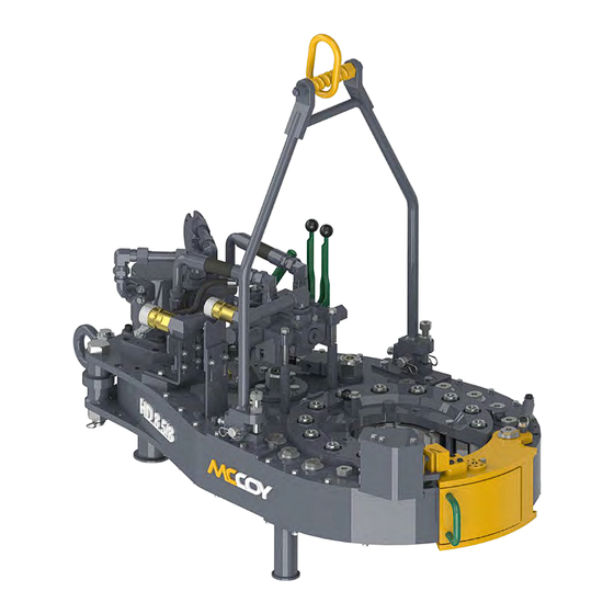
8- ” 35K T nTroDucTion Congratulations on the purchase of your FARR® HD8625 8-5/8” tong. This unit will provide you with years of outstanding per- formance. Simple maintenance and care will extend its life and ensure years of excellent performance and reliability. The setup, operating, and maintenance instructions in this manual will assist you in giving your equipment the care it requires. Please care- fully read the manual before installing and using your equipment. Replacement parts are readily available from McCoy Drilling & Completions | Farr in Edmonton, Alberta. Note that many parts are transferable between FARR® tongs and backups. Should you need replacement parts, or should you experience any difficulty not covered in this manual, please contact: McCoy Drilling & Completions | Farr 14755 121A Avenue Edmonton, Alberta Canada T5L 2T2 Phone: 780.453.3277 Fax: 780.455.2432 Sales Fax: 780.481.9246 Email Engineering: engFarr@mccoyglobal.com Email Sales: salesFarr@mccoyglobal.com Website: http://www.mccoyglobal.com/drilling-completions 1.a.1: HD8625 t llustratIon echnical anual... -
Page 14: Illustration 1.A.2: Hd8625 Power Tong Dimensions
8- ” 35K T pecificaTions 54-1/4” 1.a.2: HD8625 P llustratIon ower ImensIons echnical anual... - Page 15 8- ” 35K T pecificaTions Torque Table ** Pressure High Gear/High Speed Low Gear/Low Speed PSI / MPa Lbs.-ft. Lbs.-ft. 1000 / 6.89 9400 12745 1500 / 10.34 16100 21829 2000 / 13.78 22800 30913 2500 / 17.23 29500 39997 3000 / 20.67 1085 36200 49081 MAXIMUM RATED TORQUE: 35000 LBS.-FT. / 47454 Nm...
- Page 16 8- ” 35K T pecificaTions Use an EP synthetic grease that meets or exceeds the following specifications: Thickener Lithium Complex NLGI consistency grade NLGI performance grade GC-LB Penetration - ASTM D 217 (25°C [77°F] 265-295 minimum 0.1 mm) worked 60 strokes Dropping point, °F[°C] - ASTM D2265 550 [288] minimum High temperature life, hours - ASTM D 3527 160 minimum Oxidation stability, psi - ASTM D 942 (100 hr/300 hr) 0/3 Water washout, percent - ASTM D 1264 1.8 max Rust and corrosion - ASTM D 1743 pass Oil separation, percent loss - ASTM D 1742 1.1 max (24 hours, 25°C [77°F] Leakage, g lost - ASTM D 4290 1.0 max...
-
Page 17: Sling / Load Bearing Device Safety
BLY, FRAME, OR ANY OTHER DEVICE THAT BEARS THE PARTIAL OR TOTAL WEIGHT OF THE EQUIPMENT DESCRIBED IN THIS MANUAL) HAS BEEN SPECIFIED OR DESIGNED TO SUPPORT THE EQUIPMENT DESCRIBED IN THIS DOCUMENT. FARR® WILL NOT GUARANTEE THE ABILITY OF THE LOAD-BEARING DEVICE TO SUPPORT ANY OTHER PART, ASSEMBLY OR COMBINATION OF PARTS AND ASSEMBLIES, OR ANY ADDITIONS TO THE EQUIPMENT DESCRIBED IN THIS MANUAL THAT ADD WEIGHT TO THE EQUIPMENT, UNLESS SUPPLIED BY MCCOY. -
Page 18: Inspection Of Slings
8- ” 35K T & o eTup peraTion Inspection Of Slings McCoy Drilling & Completions strongly recommends the following practices: A complete inspection of new load-bearing devices and attachments shall be performed by a qualified, designated person prior to initial use. Each link and component shall be examined individually, taking care to expose and examine all surfaces including the inner link surface. The sling shall be examined for conditions such as those listed in the removal criteria below. In addition, daily inspection of slings, fastenings and attachments shall be performed by a designated person. If damage or defects are found at either inspection, the damaged or defective component shall be quarantined from service until it can be properly repaired or replaced. Removal Criteria: A load-bearing device shall be removed from service if conditions such as the following are present: • Missing or illegible sling identification. • Cracks or breaks • Evidence of tampering is seen - sling tag has been modified or obscured, or tamper-proof nuts are missing. • Signs of impact on load-bearing components, including spreader bars, lifting lugs, rigid slings & rigid sling weldments, and legs & leg mounts. • Broken or damaged welds. • Excessive wear, nicks, or gouges. Refer to the chart below to ensure minimum thickness on chain links supplied is not be below... -
Page 19: Proper Use Of Load-Bearing Devices
& o hD8625 8- ” 35K T eTup peraTion Units designed and manufactured in accordance with EN 12079 and DNV 2.7-1 should be tested and examined in accordance with the following schedule of examination and test. The user of the load-bearing device shall place a permanent placard or plate upon which the type and date of the last test shall be recorded. To avoid confusion, the plate shall not carry the date of the next test or examination, only the most recent. Test / Examination esTrucTive horough uffix arkeD (nDe) xaminaTion isual laTe TTacheD nTerval ifTing esTs ifTing oinTs xaminaTion Initial Certification By Farr® / Superior Interval Not Exceeding At the discretion of At the discretion of T or VN 12 Months inspection body inspection body... -
Page 20: Major Component Identification
8- ” 35K T & o eTup peraTion MAJOR COMPONENT IDENTIFICATION 2.B.1: m llustratIon ajor omPonent DentIfICatIon Item Description Master Link Rigid Sling Rear Leg Front Leg echnical anual... -
Page 21: Illustration 2.B.2: Major Component Identification
& o hD8625 8- ” 35K T eTup peraTion 2.B.2: m llustratIon ajor omPonent DentIfICatIon Item Description Tong Leveling Adjustment Backing Pin Assembly Cage Plate Assembly Safety Door Guard Safety Door Switch Door Latch Cam Adjustment Door Latch echnical anual... -
Page 22: Illustration 2.B.3: Major Component Identification
8- ” 35K T & o eTup peraTion 2.B.3: m llustratIon ajor omPonent DentIfICatIon Item Description Tong Door Assembly Tong Door Spring Cylinder Brake Band Adjustment (top adjustment shown - bottom adjustment is identical) Brake Band (top brake band shown - bottom brake band is identical) Manual Shift Assembly Torque Gauge Mount Shifter / Gear Train Inspection Panel Hydraulic Valve Assembly Hydraulic Motor Motor Mount Snub Line Shackle echnical anual... -
Page 23: Hydraulic Schematics & Valve Identification
& o hD8625 8- ” 35K T eTup peraTion HYDRAULIC SCHEMATICS & VALVE IDENTIFICATION TONG MOTOR OPTIONAL (TWO SPEED) TWO SPEED SHOWN LIFT 10 11 OPTIONAL 2.C.1: H llustratIon yDraulIC CHematIC Item Description Part Number Page Inlet Valve 10-9016 Relief Valve, 2000 - 3500 PSI 10-0062... - Page 24 8- ” 35K T & o eTup peraTion 2.C.2: H llustratIon yDraulIC omPonent DentIfICatIon 2.C.3: H llustratIon yDraulIC omPonent DentIfICatIon echnical anual...
-
Page 25: Hydraulic Connections
& o hD8625 8- ” 35K T eTup peraTion 2.C.4: H llustratIon yDraulIC omPonent DentIfICatIon HYDRAULIC CONNECTIONS A pair of hydraulic lines - a 1” supply line and a 1-1/4” return line - connect the tong to the power unit (see illustration below). Ancillary devices (hydraulic motors, hydraulic cylinders, etc.) are connected through the valve block. Perform any hydraulic connection when the power unit is not running, or when the hydraulic pump is disengaged. The possibility of error in inter-changing the high pressure supply hose and the low pressure return hose has been eliminated, because the supply side coupling is smaller than the return side. 1” Hydraulic Supply 1-1/4” Hydraulic Return 2.D.1: H llustratIon yDraulIC onneCtIons echnical anual... -
Page 26: Tong / Backup Jaw Availability & Installation
8- ” 35K T & o eTup peraTion These hose couplings are self-sealing, and care should be taken to ensure complete engagement to prevent partial closure of the check valve in the coupling. Ensure that the nut (female) side is completely made up onto the male connector - there is a line on the male fitting that indicates complete make-up. Snug the female fitting right up to the line. IMPROPERLY MADE CONNECTIONS WILL CONSTRICT OR COMPLETELY OBSTRUCT FLOW Make up female fitting to Marked point on male fitting 2.D.2: H llustratIon yDraulIC onneCtIons TONG / BACKUP JAW AVAILABILITY & INSTALLATION Availability The following table lists all jaw die kits that are available as standard sizes for this model of tong. McCoy Drilling & Completions | Farr... -
Page 27: Jaw & Die Removal
& o hD8625 8- ” 35K T eTup peraTion Jaw & Die Removal If necessary the entire jaw may be removed. Support the jaw from the bottom and remove the jaw pivot bolt. The jaw may then be slid out of and away from the cage plate. Reverse this procedure to replace the jaw assemblies (see Illustration 2.E.1) 2.e.1: j llustratIon emoval Once the jaw has been removed, extract the die keeper screws and remove the dies by tapping dies lightly with a hammer. Replace the dies, tapping them into place if necessary, and replace the keeper screws. TONG RIG-UP & LEVELING Suspension & Restraint Suspend the tong from a location as near to the centre of the drill rotary as possible, and from a location high enough on the mast to ensure easy handling. The lower the point from which the tong is suspended, the more effort will be required to move the tong to and from the connection point. The suspension line may be extended over a pulley and balanced by a counterweight equal to the weight of the tong, or simply tied off in the derrick to form a dead line. When using a dead line arrangement it is necessary to use a FARR® spring hanger assembly (see specification page for recommended spring hanger). This spring hanger compensates for the downward movement of the casing as the thread is made-up, and imparts additional force to the suspension cable: • a “single spring” hanger typically applies 420 lbs. (191 kg.) to the suspension line for every inch of thread made up • a “double spring” hanger typically applies 840 lbs. (382 kg.) to the suspension line for every inch of thread made up echnical anual 2.11... -
Page 28: Illustration 2.F.1: Tong Suspension Relative To Axial Centre
8- ” 35K T & o eTup peraTion Suspension & Restraint (Cont’d) If you do not know which specific spring hanger is in use, check the specification page in this manual for information on the recom- mended spring hanger for this application. McCoy Drilling & Completions will not guarantee or specify spring hangers other than what has been supplied by McCoy. Many applications use a lift cylinder for adjusting the height of the tong. Ensure the weight of the lift cylinder is known if it has not been included in the total weight of the tong. All forces upon the suspension line must be considered when calculating necessary strength of the suspension line. The weight of the tong, the weight of the lift cylinder, the weight of the spring hanger, and the force imparted on the suspension line by the spring hanger must all be added together in order to arrive at the total force supported by the suspension line. Select your suspension line based upon the total force and the margins of safety dictated by the policies of your company and by established engineering practices. Ultimately, calculating the force on the suspension line and selection of the suspension line is the complete responsibility... -
Page 29: Tong Leveling
& o hD8625 8- ” 35K T eTup peraTion 2.f.2: t llustratIon usPensIon elatIve ertICal entre Tong Leveling The tong must be leveled side-to-side and front-to-rear before placing into service. We have provided the following guidelines for assisting you when leveling your tong. Place a level axially (side to side) across the tong, ensuring that it is parallel with the surface of the tong. Use a thin wrench on the flat of the adjusting helix to rotate the helix, forcing the lift link to move towards the outer supports of the sling. The 3/4” nylock nut on the pin may have to be slightly loosened to allow the helix to rotate. Adjust the helix until the level shows that the tong is level side-to-side. Rotate helix using flat 3/4” Nylock nut may have to be loosened 2.f.3: t llustratIon evelIng... -
Page 30: Tong Operation
• Perform a complete inspection of all fasteners to ensure none have loosened during transport. • Connect the tong to the power unit, and apply full hydraulic pressure. Inspect and correct any leaks. • Operate the tong at full speed and in high gear for a duration of one-half hour. Hot bearing caps may indicate impending bearing failure. • Switch to low gear and operate for an additional one-half hour at full speed. • Inspect all components and hydraulic fittings for possible defects following completion of the tests. All Farr® Tongs have been thoroughly tested at the factory prior to shipping, but shipping damage must be identified before running the tong in an operational environment. • Carefully inspect the safety door components, and test to ensure that the safety device on each door is operating correctly before releasing the tong to the operating environment. TONG DOOR MUST BE CLOSED AND SECURELY LATCHED BEFORE THE POWER UNIT IS STARTED IN ORDER TO ASSURE THE SAFETY OF OPERATING PERSONNEL 2.14... -
Page 31: Valve Operation
& o hD8625 8- ” 35K T eTup peraTion Ensure adequate lube oil and hydraulic oil levels before starting engine. Use start up procedures as recommended by the power unit engine operator’s manual. Open the Bypass Valve on the hydraulic system, and inspect all pressure and return line hose connections to ensure correct and secure installation. IMPROPERLY SECURED HYDRAULIC CONNECTIONS WILL INTERRUPT HYDRAULIC FLUID FLOW, AND COULD RESULT IN THE FOLLOWING FAILURES: • A restriction in the pressure supply hose will result in high pressure within the power unit hydraulic system, which will activate the hydraulic governor and increase the engine speed to as high as maximum RPM. • A restriction in the return line will result in high pressure within the power unit and the tong hydraulic system, caus- ing engine speeds as high as maximum RPM, and possible failure of the motor seal. Following inspection of the hoses, start the engine and allow it to idle until warm. Allow hydraulic fluid to circulate for approximately 10 minutes, then slowly close the Bypass Valve to allow hydraulic fluid to circulate through the hoses and to the tong (circulating pres- sure should not exceed 200 psi). Place the tong gear shifter in low gear and rotate the tong slowly forward and then reverse with the throttle valve control lever. Once this has been done and the proper size jaws have been installed, the tong is then ready to run pipe. Valve Operation 4-way proportional valves control operation of hydraulic devices on the tong assembly such as hydraulic motors and cylinders. When... - Page 32 8- ” 35K T & o eTup peraTion Valve Operation (Continued): LIFT CYLINDER This is a direct-acting valve. Pushing the valve handle forward will cause the lift cylinder to lower the tong vertically. Pulling the valve handle toward the operator will cause the lift cylinder to lift the tong. 2.g.2: t llustratIon ylInDer ontrol alve MOTOR SPEED This valve sets the speed of the two-speed motor. Pulling the motor speed control all the way out sets the motor speed to LOW. Maximum torque is only available when the motor speed is set to LOW. Pushing the valve handle towards the centre of the tong sets the motor speed to HIGH, which is useful for rapidly un-threading broken connections. 2.g.3: t llustratIon otor PeeD ontrol alve 2.16 echnical anual...
-
Page 33: Shifting Gears
& o hD8625 8- ” 35K T eTup peraTion SHIFTING GEARS The shifting shaft has three “detent” positions identifying the low speed/high torque position, the “neutral” or free-spinning position, and the high speed/low torque position. The detent strength may be adjusted by releasing the locknut on the detent tube and increas- ing or relaxing pressure on the detent spring. Ensure the locknut is tightened once the desired detent pressure has been set. To shift to the high-speed gear, move the shifting handle downward from neutral position. To shift to the low-speed gear, move the shifting handle up through the neutral detent to its highest position. Note that the high clutch gear or the low clutch gear may not be exactly aligned when shifting, so the operator may need to “bump” the motor control handle slightly to turn the main clutch gear shaft and shifting collar into alignment. This is most effective when applying a small amount of pressure on the gear shift lever in the direction you want to shift the tong, ensuring the shifting collar will “catch” when the main clutch gear aligns with either the high or low clutch gear (see Illustration 2.G.4). SHIFTING TONG WHILE ROTATING THE MOTOR AND CAGE PLATE MAY RESULT IN CATASTROPHIC GEAR TRAIN FAILURE LIFT HANDLE TO SHIFT TO LOW GEAR... -
Page 34: Making And Breaking Connections
8- ” 35K T & o eTup peraTion MAKING AND BREAKING CONNECTIONS THESE OPERATING PROCEDURES ASSUME THE USER HAS PROPERLY SET UP AND PREPARED THE EQUIPMENT FOR OPERATION AS PER SECTIONS 2D, 2E, AND 2F OF THIS MANUAL. Set up and prepare your equipment for operation as per Section 2 of this manual Refer to the following sections: • 2.D - Hydraulic Connections... -
Page 35: Illustration 2.H.2: Backing Pin Set To "Make-Up" Position
& o hD8625 8- ” 35K T eTup peraTion Making A Connection (Continued) 2.H.2: B “m ” P llustratIon aCkIng osItIon Ensure the load cell and snub line(s) are properly configured for making up connections. A “snub line” is a length of wire rope that connects the rear of the tong body to a sturdy anchor on the drill floor (see Section 2.F.1). The snub line prevents the tong body from spinning in the opposite direction of the cage plate when torque begins to build in the joint. Farr Canada Corp. rec- ommends using two snub lines when running the equipment to eliminate uncontrolled movement in either rotational direction. The snub line(s) must be rated for the applied torque plus whatever safety margins stated by your own operating policies. The snub line connection point on the drill floor must be sturdy enough to absorb all applied forces when making up the joints. When making up joints the load cell must be connected to the driller’s side of the tong, which is the left side of the tong as seen from the rear. For accurate torque measurement the snub line between the tong body and the anchor must be perpendicular to the vertical, and perpendicular to the centre-line of the tong. Actuate the lift cylinder control valve to lift the assembly from the drill floor. Pulling the valve toward the operator will retract the lift cylinder to raise the assembly (see Illustration 2.H.3 below). Note that rig personnel are required to stabilize the tong and backup as it is being lifted so it does not swing and collide with other rig equipment. RIG PERSONNEL MUST STABILIZE THE TONG AS IT IS LIFTED FROM THE DRILL FLOOR 2.H.3: l... -
Page 36: Illustration 2.H.4: Opening Tong Door
8- ” 35K T & o eTup peraTion Making A Connection (Continued) Grasp the tong door handle and pull the door to open (See Illustration 2.H.4). Since your equipment is equipped with a safety door, opening the doors will inhibit rotation of the cage plate. 2.H.4: o llustratIon PenIng Manually engage the threads of the tubing connection being made up. Ensure threads are not cross-threaded. Move the tong on to the pipe above the tubing joint. Use the lift cylinder to ensure the tong jaws are at the correct location above the connection joint. h) Firmly close the tong door against the latch post. Begin rotation with the tong in high gear and the tong motor set to high speed (high speed/low torque). See Section 2.G.2 to set the tong motor to high speed, and Section 2.G.3 to properly set the tong to high gear. Do not shift gears while the tong is rotating. SHIFTING TONG WHILE ROTATING THE MOTOR AND CAGE PLATE MAY RESULT IN CATASTROPHIC GEAR TRAIN FAILURE 2.20... - Page 37 & o hD8625 8- ” 35K T eTup peraTion Making A Connection (Continued): Push the motor control valve toward the tong to rotate the cage plate in the make-up direction. 2.H.5: m llustratIon otor ontrol Push the rotation control handle toward the centre of the tong up to the stop once the tong jaws cam on to the tubing This threads the connection together at high speed. As the joint becomes fully made up the increasing torque demand will stall the motor, and displayed torque will increase. Stop rotation, and set motor to low speed and shift to low gear (low speed/high torque - See Section 2.G.2 for instructions for setting motor to low speed, and Section 2.G.3 for shifting to low gear). This will enable the tong to produce adequate torque for making up the joint to specification. m) Push the rotation control handle all the way in to complete the connection at low speed/high torque. Observe the torque gauge - stop rotation when the specified make-up torque is reached. Reverse the rotation control valve to release the tong jaws from the tubing (see Illustration 2.H.6). 2.H.6: m llustratIon otor ontrol eleasIng echnical anual 2.21...
-
Page 38: Illustration 2.H.7: Lift Cylinder Control - Lower
8- ” 35K T & o eTup peraTion Making A Connection (Continued): Align the opening in the rotary gear with the mouth of the tong once the jaws are free. Open the tong door. Note that rig person- nel may be required to stabilize the tong as it completely releases from the drill string. Guide the tong away from the string and use the lift cylinder control to lower it to the drill floor if desired. 2.H.7: l llustratIon ylInDer ontrol ower Repeat steps “e” through “p” until the desired number of connections are made up. 2.22 echnical anual... -
Page 39: Breaking A Connection
& o hD8625 8- ” 35K T eTup peraTion Breaking A Connection YOUR TONG SHOULD BE PROPERLY SUSPENDED, CONNECTED TO A HYDRAULIC POWER SOURCE, AND READY TO BREAK CONNECTIONS. Ensure hydraulic power supply to the tong is energized. The master link on the rigid sling must be used to suspend the tong. Do not suspend the tong directly from the rigid sling. See Illustration 2.H.1. Set the backing pin on the tong “breakout” operation. Lift up on the backing pin and rotate it to the “breakout” position, which is 2 o’clock as seen from the front of the tong. The opening in the rotary gear must be aligned with the tong door opening in order to properly set the backing pin (see Illustration 2.H.8). 2.H.8: s “B ” P llustratIon... - Page 40 8- ” 35K T & o eTup peraTion Breaking A Connection (Continued): Gently pull the motor control valve toward the operator to cam the tong jaws on to the pipe. 2.H.9: r llustratIon otatIon ontrol reak Break the connection by pulling the rotation control handle all the way out once the tong jaws cam on to the tubing. Un-thread the connection at high speed by setting the tong motor to high speed and shifting to high gear (see Section 2.G.2 to set motor speed and 2.G.3 to shift to high gear) once the connection is broken. m) Pull the rotation control handle all the way out to completely un-thread the connection. Reverse the rotation control handle (push toward tong) to release the tong jaws from the tubing. 2.H.10: u & u llustratIon sIng otor ontrol elease ollowIng reak tHreaDIng 2.24 echnical...
-
Page 41: Extreme Cold Weather Operation Procedures
& o hD8625 8- ” 35K T eTup peraTion Breaking A Connection (Continued) Align the opening in the rotary gear with the mouth of the tong once the jaws are free. Open the tong door and guide the tong away from the string, and use the lift cylinder control to lower it to the drill floor if desired. RIG PERSONNEL MUST STABILIZE THE TONG AS IT IS LOWERED TO THE DRILL FLOOR 2.H.11: l llustratIon owerIng sIng ylInDer ontrol Use your rig’s standard pipe handling procedures to remove and rack the freed tubing stand. Repeat steps “e” through “p” as many times as necessary to break out and un-thread the desired number of connections. EXTREME COLD WEATHER OPERATION PROCEDURES Consult the power unit engine operator’s manual for all cold weather operating procedures and precautions. - Page 42 This page intentionally left blank...
-
Page 43: General Maintenance Safety Practices
DO NOT PERFORM MAINTENANCE UNTIL TUBULAR CONNECTION EQUIPMENT HAS BEEN COM- PLETELY ISOLATED FROM HYDRAULIC POWER Your equipment uses materials that may be harmful to the environment if improperly disposed of (hydraulic fluid, grease, etc.). Dispose of all materials according to your company’s proscribed environmental protection regulations. CLEANING Clean tong thoroughly cleaned with a good petroleum-based cleaning agent after each job, prior to storage. Farr® recommends that the motor and valve assembly be periodically removed, along with the top tong plate, so that guides, rollers and gears can be properly cleaned (see Section 3.H, Overhaul). Ensure that cleaning solvents and chemicals are captured to prevent environmental contamination, and dispose of all materials according to your company’s proscribed environmental protection regulations. PREVENTIVE MAINTENANCE PRACTICES Regular maintenance programs are necessary, and must be established to assure safe, dependable operation of your Hydraulic Tubular Connection System and to avoid costly breakdown maintenance. The following maintenance procedures provides information required to... -
Page 44: Lubrication
8- ” 35K T ainTenance LUBRICATION Use a quality multipurpose bearing lubricant that will remain within its viscosity range at expected operating temperatures. In addition, Farr® recommends the following lubrication procedure at the completion of each job prior to storage. Farr® recommends that a liberal coating of grease be applied to the cam surface of the rotary drive gear prior to jaw installation. Periodically remove the clutch inspection plate and apply a liberal coating of grease to the clutch, drive gears and shifting shaft. Cage Plate Cam Followers Apply grease to the cam followers through the grease fittings recessed into the top and bottom cage plates (thirteen locations top, thirteen locations bottom). 3.D.1: C llustratIon ollower uBrICatIon... - Page 45 8- ” 35K T ainTenance Rotary Idlers Apply grease to the rotary idler bearings through the grease fittings recessed into the top of each shaft on the top of the tong (two locations total). 3.D.3: r llustratIon otary Dler uBrICatIon Pinion Idler Apply grease to the pinion idler bearing through the grease fitting recessed into the top of the half-shaft, located on the top face of the tong under the valve bank (one location only). 3.D.4: P llustratIon InIon Dler uBrICatIon oInt echnical anual...
-
Page 46: Illustration 3.D.5: Pinion Lubrication Points
8- ” 35K T ainTenance Pinion Apply grease to the pinion bearings through the grease fittings located on the bearing caps on the top and bottom faces of the tong (two locations top, two locations bottom). 3.D.5: P llustratIon InIon uBrICatIon oInts echnical anual... - Page 47 8- ” 35K T ainTenance Clutch Apply grease to the clutch bearings through the two grease fittings located on the clutch bearing cap on the bottom face of the tong, and the single grease fitting recessed into the end of the clutch shaft. (three locations total). 3.D.6: C llustratIon lutCH uBrICatIon oInts Motor Mount Apply grease to the motor gear/clutch drive gear through the grease fitting located on the top of the motor mount (one location only). 3.D.7: m llustratIon otor ount uBrICatIon oInt echnical anual...
- Page 48 8- ” 35K T ainTenance Shifting Shaft Apply grease to the shifting shaft and top shifting shaft bushing. The shaft and shifting yoke can be accessed through the cover plate on the side of the tong. Access shifter components through this panel 3.D.8: s llustratIon HIfter Haft uBrICatIon Door Lubrication Apply grease to the door latch adjustment cam through the grease fitting located in the top of the adjustment cam shaft. Apply grease to the contact surfaces of the safety door switch plunger. Lubricate safety door switch plunger contact area. Lubricate door latch cam through grease fitting.
-
Page 49: Brake Band Adjustment
8- ” 35K T ainTenance 10. DOOR STOP CYLINDER Periodically disassemble the door stop cylinders and coat the spring and cylinder with a general purpose lubricating oil. 3.D.10: D llustratIon ylInDer ADJUSTMENTS Brake Band Adjustment: The brake bands must be periodically adjusted to continue to provide smooth and efficient jaw cam action. If the cage plate turns with the rotary gear, the jaws will not cam properly and, therefore, will not bite on the tubing or casing. Tightening the brake band against the cage plates will increase frictional resistance, allowing jaws to cam properly and grip the casing. Adjust the brake band using the adjustment nut and bolt set as shown in the illustration below. Do not over-tighten, as this causes excessive wear to the brake bands. BRAKE BAND BRAKE BAND ADJUSTMENT BOLT AND NYLOCK NUT 3.e.1: B llustratIon rake Djustment Door Latch Adjustment Normal operation of the tong may cause wear of the door latch, which will cause the door to develop a loose fit at the latch. A latch... -
Page 50: Shifter Detent Force Adjustment
8- ” 35K T ainTenance Door Latch Adjustment (Continued); THE DOOR IS AN IMPORTANT PART OF THE STRUCTURAL INTEGRITY OF THE TONG. IT IS IMPERATIVE TO KEEP A SECURE FIT AT THE DOOR IN ORDER TO MAINTAIN PROPER GEAR ALIGNMENT, AND TO MINIMIZE THE POSSIBILITY OF DAMAGE TO THE GEAR TRAIN WHEN OPERATING THE TONG AT SPECIFIED TORQUE. -
Page 51: Recommended Periodic Checks
8- ” 35K T ainTenance RECOMMENDED PERIODIC CHECKS Door Stop Spring The spring inside the actuator cylinder must be of sufficient strength to enable the door latch mechanism to snap closed properly. Door stop spring fatigue will result in sluggish latch operation. Replace the latch spring inside the cylinder when this occurs. Shifting Shaft The shifting yoke is secured to the shifting shaft by one hex jam nut and one locknut on the bottom of the yoke. Check these nuts after each job. Do this by removing the clutch inspection plate and ensuring a snug fit prior to lubrication. Backing Pin Perform a visual inspection of the backing pin after each job. Replace the pin if stress cracks or excessive wear is found, or if the pin appears bent. Torque Gauge Assembly Periodic calibration of the torque gauge is recommended to assure accurate torque readings. When having the torque gauge ser- viced and calibrated, it is critical to note the arm length of the tong, as indicated on page 1.3. OVERHAUL PROCEDURES - DISASSEMBLY Once the tong has been removed from the backup it may be overhauled using the disassembly instructions specified in the following procedure. Access to the gear train is possible by removal of the top plate of the tong. - Page 52 16. Remove the 1-1/4” nylock nut and the three 5/8” bolts securing the pinion idler half-moon pad. 17. Pull the top pinion gear bearing cap by removing the four 1/2” bolts which secure the bearing cap. Thread two of the removed bolts into the extra holes on top of the bearing cap, and use them as lifting lugs to lift the bearing cap out of place. IF THE BEARING REMAINS ATTACHED TO THE GEAR SHAFT AFTER THE BEARING CAP IS PULLED, FARR® SERVICE PERSONNEL RECOMMENDS LEAVING IT IN PLACE UNTIL THE TOP TONG PLATE IS REMOVED. 18. Remove the jaw pivot bolts and the jaw assemblies. 19. Ensure the bottom cage plate is supported before beginning this step. Remove the two front cage plate bolt and nut sets. Remove the backing pin assembly and the rear cage plate bolt, and the cage plate spacers. The top and bottom cage plates may now be removed - Note that the cam followers are fastened to the top and bottom cage plates, so use caution not to damage them.
- Page 53 8- ” 35K T ainTenance ASSEMBLY PROCEDURES Assembly of Farr Hydraulic Power Tongs is simple, and can be accomplished without the use of special tools. The instructions on this page are presented as a guide only, and are similar to the assembly sequence our technician would use while assembling the tong in our plant. NOTE ON INSTALLATION PRACTICES: Ensure all bearings are liberally greased before installing over a shaft or into gears or bearing caps. When inserting a shaft through a support roller assembly ensure shaft is greased. Also ensure all metal-to-metal contact in the gear train is adequately greased.
-
Page 54: Assembly Procedures
8- ” 35K T ainTenance Assembly Procedures Position the tong body gear case on a suitable stationary support, ensuring that the bottom body plate remains accessible. Slide a support roller shaft spacer (PN 1037-C-134) into each support roller (PN 1037-135) (total of 12). Press support roller bearings (PN 02-0094) into each side of the support rollers. Assemble five support roller assemblies as shown on Pp. 5.4 - 5.5. Install five support roller assemblies along one side of the body case. Insert shafts through assemblies, but do not install the bottom nylock nuts or, where used, the top washers. Install rotary gear, making sure the backing pin slots are on the side facing up. Ensure one side is supported by the support rollers installed in Step 4, and have the opening in the rotary gear oriented as shown in the following illustration. 3.H.1: t llustratIon ssemBly otary nstallatIon Install support roller assemblies in the locations exposed by the opening in the rotary gear. Continue to rotate the rotary gear, install- ing support roller assemblies in the rotary gear opening as it is rotated. Finish with the rotary gear aligned with the opening in the bottom plate and completely supported by the support rollers. Do not install the door pivot support roller assembly at this time. Press pinion bearing (PN 1234-08-01B) into bottom pinion bearing cap (PN 1050-89), and install bearing cap into bottom plate of tong using four 1/2” NC x 1-1/2” hex bolts and 1/2” lock washers. Press lower clutch bearing (PN 02-0014) into clutch bearing cap (PN 101-0120), and install bearing cap into bottom plate of tong using four 3/8” NC x 1-1/2” hex bolts and 3/8” lock washers. Install a retainer clip (PN 02-0009) into both rotary idler gears (PN 997-A2-119C). Press an idler bearing (PN 02-0075) into each gear and secure with a second retainer clip. 10. Lightly grease the larger circumference of the two rotary idler shafts (PN 1050-D5-117) and slide them through the bearing and gears assemblies, centering the gear on the shaft. 11. Slide two bearing seals (PN 02-0010) over each end of the idler shafts and press against the retainer clips (see Pp. 5.6 - 5.7 for correct orientation). 12. Slide a bearing spacer (PN 1050-D5-121) over each end of the rotary idler shafts. 13. Place each rotary idler assembly through the bottom plate, ensuring the ends of the shafts with the threaded hole for the grease fitting are pointed upward and the rotary idler gears mesh with the rotary gear. -
Page 55: Illustration 3.H.2: Tong Assembly - Gear Assembly Positioning
8- ” 35K T ainTenance Assembly Procedures (continued...): 16. Install pinion gear shaft (PN 997-A7-86B) into the spline of the bottom pinion gear and the lower pinion bearing. 17. Slide 2 needle bearings (PN 02-1404) over each end of the clutch shaft (PN 997-HT-50), and press up against centre gear. Slide low clutch gear (PN 997-HT-52) over the bottom end of the clutch shaft (the bottom end of the clutch shaft can be identified by the threads for the grease fitting machined into the end) onto the two needle bearings. Ensure the smaller diameter of the low clutch gear is directly adjacent to the centre gear on the clutch shaft. Place lower end of clutch shaft into the lower clutch bearing that has been pre-mounted in the lower body plate. 18. Install shifting collar (PN 997-HT-62) over the top of the clutch shaft and mesh with low clutch gear and the centre gear on the clutch shaft. 19. Slide the shifting fork weldment (PN 1050-72) over the bottom (threaded) end of the shifting shaft (PN 1116-71) and secure with a 5/8” UNF hex nut and 5/8” UNF hex jam nut. Place the end of the shifting shaft in the lower shifting bushing (welded to the bottom plate) and mesh the shifting fork with the shifting collar. 20. Install a retainer clip (PN 02-0009) into the pinion idler gear (PN 997-A2-119C). Press an idler bearing (PN 02-0075) into the gear, and secure with the second retainer clip. 21. Slide the pinion idler half-shaft (PN 1050-D5-105) through the pinion idler gear assembly. Slide the bearing seal (PN 02-0010) over the end of the half-shaft, and secure to the half-shaft with a shaft retainer clip (PN 02-0008). 22. Place pinion idler assemblies, less the idler pads and top fasteners, on top of the lower pinion gear and place them as best as pos- sible - their position may have to be adjusted slightly as the top plate is attached (see illustration 3.H.2). 3.H.2: t llustratIon ssemBly ssemBly osItIonIng 23. The high pinion gear (PN 997-A4-87B) is machined with shoulders around the centre spline on both sides of the gear. Place the side of the high pinion gear with the larger shoulder over the top of the splined pinion shaft and press against the centre gear on the pinion shaft. -
Page 56: Illustration 3.H.3: Tong Assembly - Top Fastener Locations
8- ” 35K T ainTenance Assembly Procedures (continued...): 26. Locate the three un-threaded holes in the side body of the tong, one in the rear centre and one just to either side of the front opening. If old dowel pins are in place, remove them before installation of the top plate. If the dowel pins are in any way damaged or deformed McCoy recommends replacing them with new 3/8” x 1-1/2” hardened dowel pins. If necessary clean the dowel pin holes, and do not insert dowel pins until after the top plate has been installed. 27. Use a temporary lifting sling and crane to maneuver the top plate (PN 1050-7T) into position, and place on to the side body. Insert the three positioning dowel pins (PN 09-0092) through the top plate into their respective holes in the side body. Use a hammer to tap the dowel pins until they are flush with the top plate. Secure the top plate with 14 3/8” UNC x 1-1/2” hex bolts and 3/8” lock washers, and ten 3/8” UNC x 1” hex socket head cap screws as shown in illustration 3.H.3. Do not install fasteners at the rigid sling hanger locations, indicated by the red circles, or the door cylinder mounting lug location indicated by the green circle. 3.H.3: t llustratIon ssemBly astener oCatIons 28. Install half-moon idler pad (PN 997-D17-109) over the end of the pinion idler shaft and secure with three 5/8” NC x 2-3/4” hex bolts and 5/8” lock washers, followed by a 1-1/2” UNF nylock nut. 29. Slide the remaining rotary idler pads over the rotary idler shafts and secure with 1-1/2” UNF nylock nuts. 30. Press the remaining pinion bearing (PN 1234-08-01B) into the top pinion bearing cap and install over the top of the pinion gear shaft - secure with four 1/2” NC x 1-1/2” hex bolts and 1/2” lock washers. 31. Install top clutch bearing retainer (PN 997-HT-59) over the clutch shaft into the cutout in the top plate and secure with two 10-24 x 3/4” hex socket head cap screws. 32. Insert top clutch bearing (PN 02-1403), followed by the clutch bearing bushing (PN 997-HT-60). 33. Install clutch drive gear (PN 997-HT-61) and secure with retaining snap ring (PN 1234-00-04). - Page 57 8- ” 35K T ainTenance Assembly Procedures (continued...): 34. Re-install support roller shafts: Install all support roller shafts (PN 101-3939) that are NOT coincidental with the brake band lug weldments as shown in illustra- tion 3.H.4 (seven total). Ensure a 1-1/8” narrow flat washer is installed on the support roller shaft before inserting through the top body plate and support roller assemblies. Do not install the door pivot roller at this time. ASSEMBLY NOTE: The shafts coincidental with the front leg weldments are shown circled in red. 3.H.4: t llustratIon ssemBly uPPort ollers eCurIng ounts 34. Re-install support roller shafts continued: ii) Secure the bottoms of the support roller shafts with 1” narrow flat washers and 1” UNS thin nylock nuts. Install the RH front leg mount weldment (PN 101-0163) and the LH front leg mount weldment (PN 101-0162) on the to the support roller shafts using 1” UNS thin nylock nuts and two 3/8” UNC x 1-3/4” hex bolts and lockwashers per weldment (see Illustration 3.H.5). ASSEMBLY NOTE: Do not use flat washers when installing the 1” UNS nut on the shaft coincidental with the leg weldments . 3.H.5: t llustratIon ssemBly ront nstallatIon echnical anual 3.15...
- Page 58 8- ” 35K T ainTenance Assembly Procedures (continued...): 34. Re-install support roller shafts continued: iii) Install support roller shafts (PN 101-3939) in four locations where they are coincidental with the top and bottom brake band lug weldments (top left & bottom right weldment PN = 101-0083, top right & bottom left weldment PN = 101-0096) as shown in illustration 3.H.6. These support rollers do not use top or bottom washers. 3.H.6: t llustratIon ssemBly uPPort ollers rake BanD elDments 35. Thread the top shifter bushing (PN 101-0020) into the top plate, over the shifter shaft, until snug. Thread the detent tube (PN 101- 0019) into the top shifter bushing as shown in illustration 3.H.7. Thread three 5/8” NC x 5/8” hex socket set screws into the remain- ing three ports in the bushing - these set screws are intended to be used as contamination barriers only. Do not bottom out the set screws on the shifting shaft, or the shaft will not move. 3.16 echnical anual...
-
Page 59: Illustration 3.H.7: Tong Assembly - Top Shifter Bushing Assembly
8- ” 35K T ainTenance Assembly Procedures (continued...): 36. Insert the shifter detent ball (PN 02-0018) into the detent tube, followed by the detent spring (PN 01-0040). Thread a 7/16” NF hex jam nut onto a 7/16” UNF x 1-1/4” hex nut, then thread the 7/16” bolt into the detent tube. This is the detent force adjustment bolt and lock nut. 3.H.7: t llustratIon ssemBly HIfter usHIng ssemBly 37. Insert two 5/16” x 3/4” dowel pins (PN 09-0170) into the un-threaded holes in the rear of the tong, behind the clutch drive gear on either side of the cutout in the top plate. 38. Place motor mount (PN 1050-150) on to top plate over the dowel pins installed in the previous step, and secure with four 1/2” NC x 1-1/2” hex socket head cap screws. 39. Bolt the shifter lug weldment (PN 101-0016) onto the top plate with four 3/8” NC x 1-1/4” hex bolts and 3/8” lock washers. 40. Attach the motor gear (PN 997-A10-149) to the motor shaft, securing with two 3/8” NC x 3/8” flat point hex socket set screws. Do not neglect to install the 5/16” square x 1-1/2” key between the gear and the motor shaft.. 41. Install the motor (PN 87-0007) onto the motor mount. Secure the RH side of the motor to the motor mount with two 1/2” NC x 1” hex socket head cap screws and 1/2” lock washers. 42. The LH side of the motor is secured with two 1/2” NC x 1-1/4” hex socket head cap screws and 1/2” lock washers, which also secures the torque gauge holder weldment (PN 1500-09-04A). 43. Install shifting handle (PN 1037-D-20B). Secure the handle to the shifter shaft and shifter pivot lug weldment with 5/16” x 1-1/2 clevis pins. Use a hitch pin on each clevis pin to ensure they do not become dislodged. -
Page 60: Illustration 3.H.8: Tong Assembly - Front Cage Plate Spacers
8- ” 35K T ainTenance Assembly Procedures (continued...): 48. Insert two cage plate spacers (PN 1050-C3-38) between the cage plates at the front of the cage plates next to the rotary gear. Secure the cage plates through the spacers using 1/2” UNC x 7-1/2” hex bolts, 1/2” narrow flat washers (on the bottom) and 1/2” UNC nylock nuts. Cage plate spacers & 1/2” NC x 7-1/2” bolt and nut sets 3.H.8: t llustratIon ssemBly ront late PaCers 49. Slide a 1/2” flat washer on to a 1/2” UNC x 9-1/2” hex bolt, followed by the backing pin spacer (PN 101-4186). Slide the larger diam- eter hole in the backing pin retainer link (PN 101-4187) ever the end of the 9-1/2” hex bolt on to the backing pin spacer. 50. Coat half of the threaded connecting stud (PN 101-4097) with blue Loctite and screw in to the backing pin (PN 101-4188). 51. Insert the exposed half of the threaded dowel pin through the smaller diameter hole of the backing pin retainer link. Slide the small backing pin spacer (PN 101-4096) over the threaded dowel against the backing pin retainer link. -
Page 61: Illustration 3.H.9: Tong Assembly - Safety Door Valve Installation
8- ” 35K T ainTenance Assembly Procedures (continued...): 59. Install mechanical door stop (PN 101-1833) to the bottom plate of the tong next to the LH brake band retainer weldment. Secure with two 3/8” NC x 2” bolts and 3/8” lock washers. 60. Install the door spring cylinder (PN 101-0069) using two 1/2” x 1/2” hex socket shoulder bolts (UNC). 61. Install upper and lower lined brake band weldments (PN 1050-D4-29). Secure each brake band to the top or bottom plate with a brake band retainer (PN 101-0140),and 3/8” NC x 1” hex bolts and 3/8” lock washers. Attach the fronts of each brake band weldment to the brake band lug weldments with 3/8” UNC x 1-1/2” hex bolts, 3/8” narrow flat washers, and 3/8” UNC hex nylock nuts. These nut and bolt sets are used for adjusting the brake band tension. 62. Install the safety door switch assembly using the following procedure (see Pp. 5.30 - 5.31): Attach safety door latch spacer (PN 101-1411) to the top of the door weldment using two 3/8” NC x 1” hex socket head cap screws and 3/8” lock washers. ii. Attach safety door latch block (PN 101-1104) to the latch spacer using four 3/8” NC x 1/2” shoulder bolts. iii. Attach safety door latch block (PN 101-1103) to safety door latch plate (PN 101-1410) using three 3/8” NF x 1” flat head coun- tersunk cap screws. iv. Place the safety door latch plate (PN 101-1410) onto the bottom plate of the safety switch base and guard weldment (PN 101- 1475) and align the bolt holes. Secure to the top plate using two 3/8” NC x 2-1/4” hex socket head cap screws and one 3/8” NC x 1-1/4” socket head cap screw. Note that the two longer cap screws in this step replace two of the tong’s perimeter fasteners. Insert load plunger (PN AE12-306) into LH safety door latch block (PN 101-1103). vi. Attach three 1/4” NPT x 1/4”JIC elbows (PN 08-0284) to the Deltrol safety door valve (PN 08-0337M). Position a 15/16” valve lock nut (PN 09-0278) as shown in illustration 3.H.9, and secure the safety door valve to the safety door latch block using the valve lock nut. 3.H.9: t llustratIon... -
Page 62: Illustration 3.H.10: Tong Assembly - Rigid Sling Adjustment Bolt Installation
8- ” 35K T ainTenance Assembly Procedures (continued...): 66. Thread a 3/4” UNC hex nut on to each of two rigid sling leveling adjustment weldments (PN 1053-C-1L). Thread the leveling adjust- ment weldments into the front of the rigid sling weldment mounting brackets, roughly adjusting them so the rigid sling is approxi- mately perpendicular to the top plate of the tong (see illustration 3.H.10). 67. Thread 1/2” UNC hex nuts on to two 1/2” UNC x 1-3/4” hex bolts. Thread the bolts into the rear of the rigid sling weldment mounting brackets. (see illustration 3.H.10). 3.H.10: t llustratIon ssemBly IgID lIng Djustment nstallatIon 68. Attach the rear leg weldment (PN 997-D8-160A) to the bottom plate of the tong using a 7/8” UNC x 1” hex socket head cap screw and a regular 7/8” flat washer. 69. Install grease fittings: Install one 1/4” straight thread grease fitting (PN 02-0097) into the top side of each support roller shaft, including the door pivot rollers (12 locations total). Install one 1/4” straight thread grease fitting (PN 02-0097) into the top side of the latch adjustment cam. Install one 1/8” NPT grease fitting (PN 02-0005) into the top of each idler shaft or half-shaft (three locations total). Install one 1/8” NPT grease fitting (PN02-0005) into the end of the clutch shaft, in the centre of the clutch bearing cap. Install two 1/8” NPT 90 grease fittings (PN 02-0093) in each pinion bearing cap (four locations total). Install two 1/8” NPT 90 grease fittings (PN 02-0093) in clutch bearing cap (two locations total). Install one 1/8” NPT 90 grease fitting (PN 02-0093) or one 1/8” NPT 45 grease fitting (PN 02-0006) in the top of the motor mount. - Page 63 8- ” 35K T ainTenance Assembly Procedures (continued...): 74. Mount the DVA35 hydraulic valve assembly on the mounting posts using two 1/2” UNC x 4-1/2” hex bolts and 1/2” narrow flat wash- ers. 75. Attach two #20 (1-1/4”) / 1” JIC flange elbows (PN 02-9216) to the motor using #20 split flange kits (PN 02-9217). 76. Connect the safety door valve block (PN 101-0727) directly to the flange elbows on the hydraulic motor (the block will sit on top of the motor following installation). Connect the rotation control valve on the DVA35 valve assembly to the safety door block. 77. Connect the safety door switch to the safety door block and hydraulic valve assembly. Refer to hydraulic schematic, or call McCoy Drilling & Completions - Farr® engineering department for assistance. 78. Install desired jaw die kit in the tong using the jaw pivot bolts (PN 1050-C5-28). echnical anual 3.21...
-
Page 64: Daily Inspection & Maintenance Checklist (Power Tong)
Rotate cage plate/rotary gear until the opening in the rotary gear faces towards the rear of the tong. DO NOT PERFORM ANY FURTHER ACTIONS OR MAINTENANCE WHILE THE TONG IS CONNECT- ED TO ANY HYDRAULIC POWER SUPPLY. FARR RECOMMENDS THAT ALL HYDRAULIC LINES ARE FULLY DISCONNECTED, AND RESIDUAL HYDRAULIC PRESSURE IS BLED OFF. ENSURE ADEQUATE CONTAINMENT IS IN PLACE TO PREVENT ENVIRONMENTAL CONTAMINATION FROM RESIDUAL HYDRAULIC FLUID. - Page 65 8- ” 35K T ainTenance 13. Perform a complete greasing of the tong - refer to Maintenance section of the technical manual Ensure main supply and return connections to the tong are fully made up. Re-connect the remainder of the hydraulic lines, 14. and, if applicable, the electrical line to the turns counter. FAILURE TO ENSURE THAT THE SELF-SEALING SUPPLY AND RETURN LINES ARE FULLY MADE UP MAY RESULT IN CATASTROPHIC EQUIPMENT FAILURE. Perform a visual inspection of the load cell. If using a tension load cell, replace any cracked, broken, or distorted com- 15. ponents including links and chains. If using a compression load cell, replace any component that has been crushed or otherwise distorted through compression. Inspect hydraulic line, fittings, and diaphragm seals for fluid leaks. If applicable, inspect the load cell anchor pins (tension load cell only). Replace the anchor pins if cracking or metal distor- 16. tion is seen. If using a stand-alone power unit, start it now - refer to the power unit technical manual for startup procedures. Listen to power unit for a moment to see if there are any unusual mechanical sounds (rubbing, grinding, excessive pump noise). If using a diesel unit, allow sufficient time for the engine to reach operating temperature before increasing engine RPM. Once engine is warm, gradually increase...
-
Page 66: Monthly Maintenance Checklist - Power Tong
Rotate cage plate/rotary gear until the opening in the rotary gear faces towards the rear of the tong. DO NOT PERFORM ANY FURTHER ACTIONS OR MAINTENANCE WHILE THE TONG IS CONNECT- ED TO ANY HYDRAULIC POWER SUPPLY. FARR RECOMMENDS THAT ALL HYDRAULIC LINES ARE FULLY DISCONNECTED, AND RESIDUAL HYDRAULIC PRESSURE IS BLED OFF. ENSURE ADEQUATE CONTAINMENT IS IN PLACE TO PREVENT ENVIRONMENTAL CONTAMINATION FROM RESIDUAL HYDRAULIC FLUID. - Page 67 8- ” 35K T ainTenance Perform a visual inspection of all lifting points - if visible damage is seen, including cracks, broken lugs, distorted metal, etc. replace damaged part(s) before placing tong in service. Also inspect all chains, master links, and turnbuckles - again, if any 12. damage is noted replace the damaged part(s) before placing the tong in service. Refer to Section 2A of the technical manual (Sling/Load Bearing Device Safety) for information on recommended testing and recertification. Please note that turnbuckles with part number 101-3086 (short turnbuckles) use a high-strength pin which must be supplied by Farr. “SHORT” TURNBUCKLES HAVING PART NUMBER 101-3086 EMPLOY HIGH-STRENGTH PINS WHICH MUST BE SUPPLIED BY FARR. Remove hydraulic motor and rotate the gear train by hand, and use a flashlight to perform a visual inspection of the gear train through the access panel and the opening of the rotary gear while the gear train is being rotated. If gear damage or 13. chips of metal are seen, the tong should be removed from service and overhauled to avoid further damage. Replace access panel when inspection is complete. Inspect all jaws and dies in use for the maintenance interval. Remove pin & roller, and inspect for signs of damage - replace pins if necessary. If the pins are welded in place & the welds are found to be damaged, remove and quarantine the jaw until 14. the weld is repaired. Clean the pins and rollers, and reassemble using a liberal coating of anti-seize compound. Ensure dies are secure in the jaw & die retainers are present. Replace worn dies if necessary. Ensure that the jaw rollers rotate freely. 15. Inspect backing pin(s). If cracked, broken, or bent it (they) must be replaced. Inspect top and bottom brake band linings - replace if lining is found to be flaking or is missing pieces of material. Unequal 16.
- Page 68 8- ” 35K T ainTenance Energize power unit. Rotate tong for one minute in both high and low gear. Stop the tong and reverse the direction of 26. rotation for another minute in both high and low gear, ending with the opening of the rotary gear facing the gear train. 27. De-energize the power unit, and perform a third generous lubrication of the gear train, including the gear housing. 28. Rotate tong in low gear for 5 minutes while monitoring pressurized seals and hydraulic lines. If a seal, line, or fitting begins to leak while tong is rotating, it must be replaced before the equipment is returned to service. Rotate tong in high gear for 5 minutes while monitoring temperature of top and bottom bearing caps. If the bearing caps 29. are hot to the touch (higher than approximately 50 C) replace the applicable bearings. Likewise if the tong is making unusual noises check for damaged bearings (see Maintenance Manual for all bearing locations). Install load cell. If using a tension load cell, perform a visual inspection and replace any cracked, broken, or distorted components including links and chains. If using a compression load cell, replace any component that has been crushed 30.
-
Page 69: Tubular Connection Equipment De-Commissioning & Shipping Procedure
8- ” 35K T ainTenance TUBULAR CONNECTION EQUIPMENT DE-COMMISSIONING & SHIPPING PROCEDURE Perform the following decommissioning procedures when removing tubular connection equipment from service, with the intent of short to long-term storage. These procedures are essential for ensuring proper protection of the equipment from environmental attack, and to aid in the quick turnaround when returning the equipment to service. Store all o-rings, seals, packings, gaskets, etc. in strong moisture proof, airtight containers. Ensure that these items are not crushed, nicked, or otherwise damaged. Do not perform any further actions or maintenance while the tong is connected to any hydraulic power supply. Farr recommends that all hydraulic lines are fully disconnected, and residual hydraulic pressure is bled off. Ensure adequate containment is in place to prevent environmental contamination from residual hydraulic fluid. - Page 70 8- ” 35K T ainTenance 11. Energize power unit. Rotate tong for one minute, stop, and reverse the direction of rotation for another minute, ending with the opening of the 12. rotary gear facing the gear train. De-energize the power unit, and perform another generous lubrication of the gear train, including the gear housing. Energize power unit. Rotate tong for one minute, stop, and reverse the direction of rotation for another minute, ending with 13. the opening of the rotary gear facing the gear train. 14. De-energize the power unit, and perform a third generous lubrication of the gear train, including the gear housing. 15. Energize power unit, and rotate the tong for a final time, one minute in one direction, stop, and reverse the direction of rota- tion for another minute, this time ending with the rotary gear in the “open throat” position. Extend all hydraulic cylinders, and inspect cylinder rods for signs of mechanical damage, flaking, or rust. Farr recommends 16. that damaged cylinders be replaced prior to storage. If you are using a frame-mounted tool, the tong must be lowered onto the backup in order to remove the risk of sudden and catastrophic movement when pressure is removed from the float cylinders. Cover the top of the backup with protective cloth to protect the paint on the backup. Place two wooden beams across the top of the tong, ensuring that the beams have a 17. minimum size of 4” x 4” x the width of the tong. Cover the tops of the wooden beams with more protective cloth to prevent paint damage to the tong. When lowering the tong onto the beams, ensure that the beams come into flat contact with the bottom of the tong, away from bearing caps, brake bands, or other protrusions on the bottom of the tong. Ensure that the tong hanger chains are loose, but not dangling into contact with the hangers or top plate of the tong. ePressurIzatIon roCeDure torage Rotate the tong to the “open throat” position. Exercise each hydraulic cylinder several times - open the tong and backup doors (if equipped), retract and extend the remote backing pin ramp (if equipped), retract and extend the float cylinders. Leave all cylinders except for the door cylin-...
-
Page 71: Illustration 3.L.1: Shipping Instructions - Pallet
8- ” 35K T ainTenance 23. Allow the anti-corrosive coating ample time to dry - refer to manufacturer data sheets for drying times at room temperature. Wrap entire assembly in 100 gauge (1 mil) corrosion-inhibiting wrap, at least 3 layers thick. Attempt to ensure that the tool 24. is well-sealed within the wrapping, including the bottom. If possible, store in a sealed, climate controlled environment. If isolated storage is not available, Farr recommends storing your wrapped equipment in a secure, out-of-the-way location, using silica gel desiccant to reduce the humidity within the wrapping. As a guideline, use 125 g. of desiccant for each cubic metre of space, or 3.5 g. per cubic foot. alCulatIon equIreD esICCant Calculate the trapped air volume by measuring the outside dimensions of the tool to be stored, and treat that as the volume to be stored. For example, the external dimensions of a KT20000 20” power tong are 80.25” x 50.5” x 28”, which calculates to an approximate volume of 113500 in , or 66 ft (1.87 m Multiply the calculated air volume, in cubic feet, by the recommended amount of desiccant per cubic foot. Carrying forth the example used in the previous step, the required desiccant charge would be 3.5 g. x 66 ft , equaling 231 g. Several manufacturers offer silica gel desiccant in packaged quantities of 125 grams per bag, so two packages of desiccant would be required. Please keep in mind that this is a guideline only - more or less desiccant may be required in extreme environmental conditions. For best corrosion resistance the equipment should be removed from storage and exercised on a regular basis, depending on the storage environment. Farr recommends that for equipment stored in a salt-water maritime or exposed dusty environment, repeat steps 9 through 24 monthly. For equipment stored in isolated storage in a non-maritime environment, repeat steps 9 through 24 quarterly. Replace desiccant packs at this time - depleted desiccant packs may be treated as regular dunnage. HIPPIng nstruCtIons The following procedure lists the steps to be followed to prepare your tong for shipping. If not already done remove accessories (tong jaws, load cell, torque gauge, etc.) McCoy recommends wrapping these items in protective wrap and placing in a separate wooden crate. -
Page 72: Illustration 3.L.2: Shipping Instructions - Wrapping Chain Sling & Strapping To Pallet
8- ” 35K T ainTenance HIPPIng nstruCtIons ontInueD Use a crane to support the chain sling (if equipped). Wrap the chain sling with bubble wrap or another similar protective wrap- ping, and secure the wrapping with tape. Lower the wrapped chain sling so it sits inside the opening of the tong. 3.l.2: s & s llustratIon HIPPIng nstruCtIons raPPIng HaIn lIng traPPIng allet Securely strap the equipment in place using metal strapping (see Illustration 3.L.2). Place strapping as close to the cross- members under the equipment legs as possible, and use caution not to entrap any flexible hydraulic hoses beneath the strapping (guide strapping through beneath the hydraulic hoses). Use the following guidelines to determine the strapping requirements:... -
Page 73: Tubular Connection Equipment Re-Commissioning Procedure
8- ” 35K T ainTenance TUBULAR CONNECTION EQUIPMENT RE-COMMISSIONING PROCEDURE Perform the following recommissioning procedures when removing tubular connection equipment from short or long-term storage back into regular service. These procedures are essential for ensuring proper equipment preparation and operation. The following procedures also assume that the decommissioning and storage procedures recommended by Farr have been strictly observed. Remove all protective plastic wrapping. If there are desiccant packs with the assembly, they may be disposed of with the 1. regular garbage. 2. Remove the access panel on the side of the tong directly adjacent to the shifter mechanism. 3. Wipe excess grease or heavy oil from exposed cylinder rods. - Page 74 8- ” 35K T ainTenance Perform a full functional test of the equipment including, if applicable, backup components and float frame components. Report 20. and correct any hydraulic leaks from the hydraulic valve bank, or from any hydraulic cylinders that are used. If using a frame-mounted tong and backup system, raise the tong off the beams that it is resting upon. Remove the beams 21. and protective cloths - inspect the paint on top of the backup and the bottom of the tong to ensure it has not been damaged by the beam. Test safety door feature (if equipped). Open the tong door(s), and attempt to rotate the cage plate at low speed (low gear) in both directions (makeup and breakout). If cage plate begins rotating, the safety door mechanism is not functional, and the tong 22. must be removed from service until the safety door mechanism can be repaired. If the safety door is operating correctly, cage plate rotation will not be inhibited once the door is closed and latched. NEVER OPERATE YOUR EQUIPMENT WITH A BYPASSED OR MALFUNCTIONING SAFETY DOOR While rotating the cage plate, ensure that the jaws properly cam. If the jaws do not cam properly, the brake bands need to be 23. tightened. Incrementally adjust both the top and bottom brake bands EQUALLY until proper cam action is achieved. 24. When all of the previous steps are completed, you may return your re-commissioned equipment to service. 3.32 echnical anual...
-
Page 75: Tong Will Not Develop Sufficient Torque
8- ” 35K T roubleshooTing Adequate maintenance and proper fluid selection is essential for minimizing hydraulic-related failures. All troubleshooting must be performed by a technician trained in hydraulic systems, and familiar with the equipment design, assembly and operation. The following troubleshooting instructions are intended to be guidelines only. Any faults not solved through the use of this guide should be referred to our engineering department for their evaluation and recommendations. TONG WILL NOT DEVELOP SUFFICIENT TORQUE POSSIBLE PROBLEM SOLUTION(S) Malfunctioning relief valve on tong hydraulic circuit See Section 4.B, Relief Valve Troubleshooting Check directional valve. Neutral position should return fluid directly to the reservoir. Directional valve is leaking Replace or repair valve to ensure correct operation Power unit is not producing adequate pressure Troubleshoot power unit (see user’s manual for your particular unit) Poor hydraulic pressure at the tong despite ade- Restrictions exist in line between power unit and tong. Inspect integrity of self-seal- quate pressure at the power unit, or excessive ing couplings to ensure they are allowing full fluid flow. Check to ensure no other... -
Page 76: Relief Valve Is Incorrectly Set Or Not Functioning
8- ” 35K T roubleshooTing RELIEF VALVE IS INCORRECTLY SET OR NOT FUNCTIONING POSSIBLE PROBLEM SOLUTION(S) Relief pressure set too low, resulting in insufficient tong torque Adjust setting (See following procedure): Relief pressure set too high, resulting in crushed pipe or gear train failure If your tong is equipped with a system pressure indicator proceed to step “f”. If your tong does not have a system pressure indicator, a temporary 0 - 3000 PSI indicator must be installed on the hydraulic inlet. Isolate your tong from hydraulic power, and depressurize following the procedure in section 3.D. Tee in a temporary indicator at the safety door supply pressure port. Ensure all hydraulic connections are performed by a qualified hydraulic technician. Connect a temporary 0 - 3000... - Page 77 8- ” 35K T roubleshooTing RELIEF VALVE IS INCORRECTLY SET OR NOT FUNCTIONING Cont’d: POSSIBLE PROBLEM SOLUTION(S) Debris on valve seat Relief cannot be adjusted to maximum system pres- Valve spring is broken sure (high fluid bypass results in low system pressure Valve spring has lost spring force due to continuous tension PROCEDURE: Isolate your tong from hydraulic power, and depressurize following the procedure in section 3.D Loosen the locking nut on the pressure relief valve. Use a large flat-head screwdriver to completely un-thread the poppet and spring from the relief assembly. Inspect the relief valve spring, poppet, and valve seat. If no debris is found in relief valve and if seat and poppet are undamaged, replace relief valve spring. Reassemble relief valve. Relief valve must be re-set to allow maximum system pressure. Follow the procedure in Step 1 of this section to properly adjust relief valve. If maximum system pressure still cannot be reached, replace the entire relief valve assembly.
-
Page 78: Safety Door Does Not Operate Or Is Malfunctioning
8- ” 35K T roubleshooTing SAFETY DOOR DOES NOT OPERATE OR IS MALFUNCTIONING POSSIBLE PROBLEM SOLUTION(S) Safety door switch requires adjustment. Adjust switch as per section 3.F.5 Safety door switch has failed Test safety door switch for proper function and replace if necessary Contamination in hydraulic lines Ensure all three flexible hydraulic lines to safety door switch are free-flowing Pilot-to-open valve in safety door valve block is Remove each valve. Inspect seats and springs. Replace valve(s) if damage is seen malfunctioning. on valve seats, or if spring appears to be damaged or broken. echnical anual... -
Page 79: Tong Running Too Slowly
8- ” 35K T roubleshooTing TONG RUNNING TOO SLOWLY POSSIBLE PROBLEM SOLUTION(S) Inspect self-sealing couplings to ensure they are properly engaged Obstruction in tong hydraulic circuit preventing The main hydraulic lines (supply and discharge) to the tong are obstructed. Remove adequate flow and clean if required Power unit is not producing adequate flow or Troubleshoot power unit (see user’s manual for your particular unit) pressure Tong motor is excessively worn and is leaking... -
Page 80: Failure Of Jaws To Grip Pipe
8- ” 35K T roubleshooTing FAILURE OF JAWS TO GRIP PIPE POSSIBLE PROBLEM SOLUTION(S) Dies have become too dull to provide adequate grip Replace dies Double-check jaw size to ensure they are rated for the diameter of pipe or Incorrect jaws are being used casing being run Ensure dies loaded in the jaws are appropriate for the type of pipe or casing Incorrect dies are being used being run Brake band(s) is (are) insufficiently adjusted, not allow- Adjust brake bands to give proper resistance to cage plates ing jaws to cam properly Remove jaw assembly and inspect. Replace rollers that are visibly “flat-spot- Jaw roller broken or worn ted” or otherwise damaged... -
Page 81: Failure Or Difficulty Of Tong To Shift
8- ” 35K T roubleshooTing FAILURE OR DIFFICULTY OF TONG TO SHIFT POSSIBLE PROBLEM SOLUTION(S) Bent or broken shifter handle Replace shifter handle Bent or broken shifter yoke Inspect components through inspection door. Replace shifter yoke if necessary. Bent or broken shifter shaft Replace Locking nuts on shifting shaft have loosened and posi- Reposition yoke and re-tighten locking nuts tion of yoke has changed Inspect yoke and inspect for damage. If free of damage, replace on shaft and Shifting yoke has come loose from shifting shaft tighten locking nuts Tong pops out of gear Adjust shifter detent force (See Pg. 3.8) Lubricate shifting shaft. May require shifter shaft removal and cleaning of var- “Frozen” or hard to move shifter handle nish or other deposits on the shaft. echnical anual... -
Page 82: General Comments
8- ” 35K T roubleshooTing GENERAL COMMENTS The following factors generally contribute to poor hydraulic operation and premature wear of equipment: Contaminated hydraulic fluid due to overuse, overheating, or inadequate fluid filtration. Unsuitable hydraulic fluid, especially in extreme climatic conditions. Defective packing or seals in components of the hydraulic system. Poor or incomplete hydraulic system training. Users must be fully qualified to operate the equipment, and have complete understand- ing of the hydraulic system. If your hydraulic troubleshooting procedures involve flow and pressure tests at the power unit, McCoy Drilling & Completions recommends construction of a test rig that can easily be connected to the main suction and discharge ports of the power unit. echnical anual... - Page 83 8- ” 35K T HD8625 8- ” 35K Tong Parts and Assemblies echnical anual...
-
Page 84: Gear Train Layout
8- ” 35K T rain ayouT echnical anual... - Page 85 8- ” 35K T rain ayouT ITEM TYPE DESCRIPTION PART NUMBER Part Hydraulic Motor 87-0007 Assembly Clutch Assembly (See Pp. 5.14 - 5.15) Assembly Pinion Assembly (See Pp. 5.12 - 5.13) Assembly Rotary Idler Assembly (See Pp. 5.8 - 5.9) Assembly Support Roller Assembly (See Pp. 5.4 - 5.5) Part Rotary Gear 1172-D1-HT Assembly Cam Follower Assembly (See Pp. 5.18 - 5.19) Assembly Door Pivot Roller Assembly (See Pp. 5.6 - 5.7) Assembly Shifter Assembly (See Pp. 5.16 - 5.17) Assembly Pinion Idler Assembly (See Pp. 5.10 - 5.11) Part Motor Gear 997-A10-149 echnical anual...
- Page 86 8- ” 35K T upporT oller echnical anual...
-
Page 87: Support Roller
8- ” 35K T upporT oller Item Type Description Part Number Part 1/4” Straight Thread Grease Fitting 02-0097 Part Support Roller Shaft 101-3939 Part 1-1/8” Narrow Flat Washer 02-0471 Part Support Roller Spacer 101-3871 Part Bearing 02-0094 Part Support Roller Internal Spacer 1037-C-134 Part Support Roller 1037-135 Part 1” Narrow Washer 09-5120 Part 1” UNS Thin Nylock Nut 09-9167 Where support rollers are coincidental with brake band lug weldments upper and lower washers are not used. Where support rollers are coincidental with leg mount weldments lower washers are not used. - Page 88 8- ” 35K T ivoT oller echnical anual...
- Page 89 8- ” 35K T ivoT oller Item Type Description Part Number Part 1/4” Straight Thread Grease Fitting 02-0097 Part Door Pivot Roller Shaft 101-3939 Part 1-1/8” Narrow Flat Washer 02-0471 Part Support Roller Spacer 101-3871 Part Bearing 02-0094 Part Support Roller Internal Spacer 1037-C-134 Part Support Roller 1037-135 Part 1” Narrow Washer 09-5120 Part 1” UNS Thin Nylock Nut 09-9167 echnical...
- Page 90 8- ” 35K T oTary Dler sseMbly echnical anual...
- Page 91 8- ” 35K T oTary Dler sseMbly Item Type Description Part Number Part 1/8” NPT Grease Fitting 02-0005 Part 1-1/4” UNF Hex Nylock Nut 09-5740 Part Idler Pad 997-D20-125 Part Rotary Idler Spacer 1050-D5-121 Part Rotary Idler Shaft 1050-D5-117 Part Bearing Seal 02-0010 Part Retaining Ring 02-0009 Part Bearing 02-0075 Part Rotary Idler Gear 997-A2-119C...
- Page 92 8- ” 35K T inion Dler sseMbly 5.10 echnical anual...
- Page 93 8- ” 35K T inion Dler sseMbly Item Type Description Part Number Part Grease Fitting, 1/8” NPT 02-0005 Part 1-1/2” UNF Hex Nylock Nut 09-5740 Part 5/8” UNC x 2” Hex Bolt 09-1234 Part 5/8” Lock Washer 09-5114 Part Idler Pad 997-D17-109 Part Pinion Idler Half Shaft 1050-D5-105 Part Retaining Ring 02-0009 Part Bearing 02-0075 Part Pinion Idler Gear 997-A2-119C...
- Page 94 8- ” 35K T inion sseMbly 5.12 echnical anual...
-
Page 95: Pinion Assembly
8- ” 35K T inion sseMbly Item Type Description Part Number Part 1/8” NPT 90 DEG Grease Fitting 02-0093 Part 1/2” NC x 1-1/2” Hex Bolts 09-1170 Part 1/2” Lock Washers 09-5110 Part Pinion Bearing Cap 1050-89 Part Pinion Bearing 1234-08-01B Part High Pinion Gear 997-A4-87B Part Pinion Gear Shaft 997-A7-86B Part Low Pinion Gear 997-A5-88 echnical anual 5.13... -
Page 96: Clutch Assembly
8- ” 35K T luTch sseMbly 5.14 echnical anual... - Page 97 8- ” 35K T luTch sseMbly Item Type Description Part Number Part Outside Snap Ring 1234-00-04 Part Drive Gear 997-HT-61 Part #10-24 x 3/4” Hex SHCS 09-0001 Part Top Clutch Bearing Spacer 997-HT-60 Part Top Clutch Spacer 101-3599 Part Top Clutch Bearing 02-1403 Part Top Bearing Retainer 997-HT-59 Part Bearing Retainer Spacer 101-5312 Part High Clutch Gear 997-HT-51B Part...
- Page 98 8- ” 35K T hifTer sseMbly 5.16 echnical anual...
- Page 99 8- ” 35K T hifTer sseMbly Item Type Description Part Number Weldment Shifting Handle Weldment 1037-D-20B Part HITCH PIN .0930 X 1.125 02-0274 Part Detent Ball 02-0018 Part 7/16” UNF x 1-1/4” Hex Bolt 09-1608 Part 7/16” UNF Hex Jam Nut 09-5508 Part Detent Spring 997-0-64 Part 5/8” UNC x 5/8” Hex Socket Set Screw 09-2011 Part Shifting Shaft 101-2816 Weldment Shifting Fork Weldment 997-HT-72 Part 5/8” UNF Hex Nut...
- Page 100 8- ” 35K T oTary sseMbly 5.18 echnical anual...
- Page 101 8- ” 35K T oTary sseMbly Item Type Description Part Number Part 1/2” UNC x 9-1/2” Hex Bolt 09-1203 Part 1/2” Regular Flat Washer 09-5010 Part Backing Pin Spacer 101-4186 Part Jaw Pivot Bolt 1050-C5-28 Part 1/2” UNC x 7-1/2” Hex Bolt...
-
Page 102: Leg Weldments
8- ” 35K T elDMenTs 5.20 echnical anual... - Page 103 8- ” 35K T elDMenTs Item Type Description Part Number Weldment Rear Leg Weldment 997-D8-160A Weldment LH Leg Weldment 101-0162 Part Regular 7/8” Flat Washer 09-5022 Part 7/8” UNC x 1-1/4” Hex Socket Head Cap Screw Weldment RH Leg Weldment 101-0163 Part 1” Narrow Washer 09-5120 Part 1” UNS Thin Nylock Nut 09-9167 Part 3/8” NC x 2” Hex Bolt 09-1054 Part 3/8” Carbon Steel Lock Washer 09-5106 echnical anual 5.21...
- Page 104 8- ” 35K T yDraulic upporTs 5.22 echnical anual...
-
Page 105: Hydraulic Supports
8- ” 35K T yDraulic upporTs Item Type Description Part Number Part 1/2” UNC x 4-1/2” Hex Bolt Part Hydraulic Valve Mount Post 101-0116 Part 3/8” NC x 1” Hex Bolt 09-1046 Part 3/8” NC x 2” Hex Bolt Part Adjustable Plate - Discharge Line Support 101-0277 Part 3/8” Carbon Steel Lock Washer 09-5106 Part Discharge Line Support Mounting Plate 101-0023 Part Discharge Line Support Mounting Base 101-0021 Part 1/2” Carbon Steel Lock Washer Part Adjustable Plate - Inlet Line Support 101-0022 Weldment... - Page 106 8- ” 35K T & M oTor oTor ounT 5.24 echnical anual...
- Page 107 & M hD8625 8- ” 35K T oTor oTor ounT Item Type Description Part Number Weldment Torque Gauge Mount Weldment 1500-09-03A Part 1/2” NC x 1-1/4” Hex Socket Head Cap Screw 09-2168 Part 1/2” NC x 1 Hex Socket Head Cap Screw Part 1/2” Lock Washer 09-5110 Part Two-Speed Hydraulic Motor 87-0007 Part Motor Gear 997-A10-149 Part 3/8” NC x 3/8” Hex Socket Set Screw 09-0106 Part 1/2” NC x 1-1/2” Hex Socket Head Cap Screw Part 1/8” NPT 90 DEG Grease Fitting 02-0093 Part #20 (1-1/4”)/JIC 1” Flange Elbow...
- Page 108 8- ” 35K T raKe anDs 5.26 echnical anual...
- Page 109 8- ” 35K T raKe anDs Item Type Description Part Number Part 3/8” x 1” Hex Cap Screw 09-1046 Part 3/8” Lock Washer 09-5106 Part Brake Band Retainer 101-0140 Weldment Lined Brake Band Weldment 1050-D4-29 Weldment Brake Band Lug Weldment (Top Right, Bottom Left) 101-0096 Weldment Brake Band Lug Weldment (Bottom Right, Top Left) 101-0083 Part 3/8” Narrow Flat Washer 09-5124 Part 3/8” UNC Thin Nylock Nut Part 3/8” UNC x 1-1/4” Hex Bolt 09-1048 echnical anual 5.27...
- Page 110 8- ” 35K T sseMbly 5.28 echnical anual...
- Page 111 8- ” 35K T sseMbly Item Type Description Part Number Part 3/8” UNC x 3/4” Hex Bolt 09-1044 Part 3/8” Carbon Steel Lock Washer 09-5106 Part 1/8” NPT Grease Fitting 02-0005 Part Adjustment Cam 1037-A-14 Assembly Safety Door Latch Block Assembly (Pp. 5.30 - 5.31) Weldment Door Weldment 1050-C4-10 Part 1/2” Lock Washer 09-5110 Part 1/2” UNC Hex Nut 09-9124 Part 1/2” x 1-3/4” Hex Bolt 09-2172 Weldment Door Latch Weldment 1050-15...
- Page 112 8- ” 35K T afETy PTION 5.30 echnical anual...
- Page 113 8- ” 35K T afETy PTION Item Type Description Part Number Part 3/8” x 1/2” Shoulder Bolt, UNC 09-0125 Part Safety Door Latch Block 101-1104 Part 15/16” Valve Lock Nut 09-0278 Part Safety Door Latch Block 101-1103 Part 3/8” UNC x 1” Hex Socket Head Cap Screw 09-1738 Part Safety Door Latch Spacer 101-1411 Part 3/8” UNC x 1-1/2” Hex Bolt 09-1553 Part 3/8” Carbon Steel Lock Washer 09-5106 Part Safety Door Latch Plate 101-1410 Part 3/8” UNC x 1” Hex Socket Flat Countersunk Cap Screw...
-
Page 114: Rigid Sling Assembly
8- ” 35K T igiD ling sseMbly 5.32 echnical anual... - Page 115 8- ” 35K T igiD ling sseMbly ALL FASTENERS USED TO ASSEMBLE LOAD-BEARING COMPONENTS (CHAIN SLINGS, RIGID SLINGS, BACKUP LEGS) MUST BE TIGHTENED TO THE CORRECT TORQUE. 3.11 Item Type Description Part Number Part Lifting Link 02-0516 Part Rigid Sling Adjustment Helix 1053-1-H Part 3/4” NC x 9” Hex Bolt...
- Page 116 This page intentionally left blank...
-
Page 117: Basic Torque Measurement
8- ” 35K T orque easureMenT BASIC TORQUE MEASUREMENT Basic torque measurements are performed using a simple hydraulic measurement system. A hydraulic load cell connects to a calibrated torque gauge through a reinforced flexible hydraulic hose. The torque gauge is factory-calibrated to display accurate torque measurements for a tong or tong and backup assembly with a particular arm length. The arm length is a measurement from the centre of the pipe or cas- ing to the centre of the force being applied to the load cell. Two load cell options are available. A tension load cell is typically used with a suspended stand-alone tong. This application requires that the load cell be attached to the rear of the tong as part of the restraint line that opposes the force generated when the tong makes up or breaks out a joint. A compression load cell is used in a tong and backup assembly, and is typically located on the rear of the backup between the backup and a stationary frame. The load cell must be located in the centre of the compression force vector generated between the backup and the frame. Hydraulic force generated by a load cell is transmitted to the torque gauge via a reinforced flexible hydraulic line. The hydraulic force is displayed as torque in units of Ft.-Lbs. The torque gauge has a red “peak torque” indicator that tracks with the torque gauge needle to the point of highest torque, and remains at the point of highest torque until manually reset. Note that every model of tong and tong and backup assembly has a unique arm length, and the torque gauge must be calibrated for that arm length. Torque gauges that are not calibrated for the arm length of the tool in service will not display correct torque. To ensure correct torque measurement, ensure the arm... - Page 118 8- ” 35K T orque easureMenT BASIC TORQUE MEASUREMENT (Continued:) The images on the preceding page are for illustration purposes only and may not accurately represent the torque gauge and load cell that have been supplied with your equipment. Please note that the parts listed in the following table are correct for accurate torque measure- ment while using the equipment for which this manual is supplied. THE TORQUE GAUGE USED IS FULLY DEPENDANT UPON THE ARM LENGTH AND TORQUE RANGE OF THE EQUIPMENT IN USE. THE PART NUMBERS LISTED IN THE FOLLOWING TABLE ARE CORRECT FOR ACCURATELY MEASURING TORQUE USING THE EQUIPMENT FOR WHICH THIS MANUAL IS SUPPLIED.
- Page 119 Item Type Description This is the standard tension load cell supplied by McCoy Drilling & Completions | Farr. Contact our sales depart- Assembly Tension Load Cell, 4.08 in ment for information about optional application- Part 1/4” NC x 1/2” Binding Head Machine Screw specific tension load cells.
-
Page 120: Illustration 6.A.5: Turn Counter Encoder Mount Exploded
8- ” 35K T orque easureMenT Item Type Description Part Number Assembly Standard Turn Counter Encoder Mount 60-0001 Part 6-32 x 3/8” Hex Socket Head Set Screw Part Helical Flexible Encoder Shaft Coupling 60-0130N Part Internal Retainer Ring 1376-13... -
Page 121: Troubleshooting
8- ” 35K T orque easureMenT TROUBLESHOOTING Under normal operating conditions, and with proper maintenance, the torque gauge and load cell system are designed to give lasting trouble-free performance. Faulty indication on the gauge will very often define a fault within the gauge. IF TROUBLESHOOTING REVEALS THAT THERE IS INSUFFICIENT FLUID IN THE SYSTEM, BEFORE RECHARGING, CHECK THAT ALL SYSTEM COMPONENTS ARE FREE FROM DAMAGE. THIS WILL ENSURE THAT FLUID LOSS WILL NOT CONTINUE AFTER RELOADING Symptom: No indication on gauge. Possible Problem: Obstruction in hydraulic hose. Solutions: Check hydraulic hose for kinks. Replace hydraulic hose. Possible Problem: Loss of hydraulic fluid. Solution: Recharge hydraulic fluid (see Section 6.C). NOTE: Ensure any breaches in the hydraulic system between the load cell and torque gauge are repaired to prevent further fluid loss. Possible Problem: Internal mechanism of torque gauge is damaged. Solution: Replace gauge. Symptom: Gauge indication unexpectedly high. Possible Problem: Excessive hydraulic fluid. Solutions: Completely drain hydraulic fluid from torque gauge/load cell system. Recharge following the procedure in Section 6.C. -
Page 122: Periodic Inspection And Maintenance
UN-CONTAINED SPILLAGE OF THE HYDRAULIC FLUID IN THIS SYSTEM MAY CONTRAVENE GOV- ERNMENTAL ENVIRONMENTAL REGULATIONS, OR THE ENVIRONMENTAL REGULATIONS AND POLICIES OF YOUR COMPANY. FARR CANADA CORP. HIGHLY RECOMMENDS PLACING YOUR LOAD CELL IN A CONTAINMENT BASIN BEFORE PROCEEDING WITH THE BLEEDING & REFILLING PROCESS. -
Page 123: Repair And Calibration
8- ” 35K T orque easureMenT Reference Checking Your Torque Measurement System (continued): Tension Load Cell (continued): Perform a simple calculation to determine the expected indication on the torque gauge based on the known hoisted weight. This is a calculation that must be performed using imperial units (eg., pounds and feet). The calculation is: [KNOWN WEIGHT] x [ARM LENGTH (in feet)]. For example, if the arm length is 36 inches and the hoisted weight is 1000 lbs the calculation is: 1000 x (36/12) = 3000 Therefore, the expected indication on the torque gauge should be 3000 lbs-ft. Repair And Calibration Return the load cell and indicator gauge to the authorized repair facility for repairs and calibration. echnical anual... - Page 124 This page intentionally left blank...
- Page 125 8- ” 35K T Section 7: Hydraulic Component Information The manufacturer information contained in this section has been obtained from publicly available web sites and has been provided for information purposes only. McCoy Drilling & Completions does not guarantee the accuracy of the information contained in this section. All original copyrights claimed by the manufacturer(s) apply. echnical anual...
- Page 126 Available in single or two speed. hD8625 8- Eight displacements ranging from ” 35K T yDraulic oMponenTs 6 in to 15 in POWER to be the Best! Envelope dimensions remain the same regardless of displacement. HYDRAULICS, INC.
- Page 127 8- ” 35K T yDraulic oMponenTs Technical Information - All Styles VANE CROSSING VANE FILTRATION 25 micron minimum. The Rineer patented vane crossing vane design produces much higher volumetric and mechanical efficiencies than is FLUID possible with a standard vane type design. This design...
- Page 128 NEAR AND FAR SAE 14T 12/24 PITCH hD8625 8- ” 35K T yDraulic oMponenTs OPTIONAL SHAFT FLAT ROOT SIDE FIT INVOLUTE SPLINE 15 Series Two Speed Envelope 2.18 7.80 1/4 O-RING BOSS 6.82 5.80 CENTER LINE 3.41 1.62 CASE EFF.
- Page 129 8- ” 35K T yDraulic oMponenTs Technical Information - Two Speed Motor OPEN DURING CROSSOVER SPOOLS DISPLACEMENT CHANGE When a motor is shifted from full to partial displacement the Open during crossover spools allow port "A" to be directly motor is changed to 50%, 35%, or 28% of its original connected to port "B"...
- Page 130 8- ” 35K T yDraulic oMponenTs Performance Data - Selected Displacements 6 C.I.D. C.I.D. ACTUAL TORQUE AND POWER 6-CID ACTUAL TORQUE AND POWER 9.5-CID 1700 RPM 2000 RPM 100 RPM 100 RPM 2000 RPM 1700 RPM 1600 RPM 1300 RPM...
- Page 131 8- ” 35K T yDraulic oMponenTs Model Code M015 - 61/62 -015 -000 Special Code Designator M015 - 61 = 015 Single Speed M015 - 62 = 015 Two Speed Seal - Package Selection Options: Bearing Package Selection 62 = Two Speed Single Pilot...
- Page 132 8- ” 35K T yDraulic oMponenTs Repair Manual 15 Series HYDRAULICS, INC. HYDRAULICS, INC. Standard Motor Two Speed Motor echnical anual 331 BREESPORT * SAN ANTONIO, TX 78216 * (210) 341-6333 FAX (210) 341-1231...
- Page 133 8- ” 35K T yDraulic oMponenTs echnical anual...
- Page 134 8- ” 35K T yDraulic oMponenTs WARNING: RINEER RECOMMENDS FOLLOWING ALL STANDARD SHOP SAFETY PRACTICES SPECIFICALLY INCLUDING WEARING OF EYE PROTECTION. REMOVAL OF SHAFT SEAL 1) Two of the 3/8" bolt holes are provided with jack screw threads. 1) Remove snap ring 2) Insert a piece of 1/4"...
- Page 135 8- ” 35K T yDraulic oMponenTs WARNING: RINEER RECOMMENDS FOLLOWING ALL STANDARD SHOP SAFETY PRACTICES SPECIFICALLY INCLUDING WEARING OF EYE PROTECTION. DISASSEMBLY OF FRONT DISASSEMBLY OF ROTOR/STATOR HOUSING AND SHAFT CARTRIDGE 1) Mark one side of the Lift up rotor/stator cartridge...
- Page 136 8- ” 35K T yDraulic oMponenTs WARNING: RINEER RECOMMENDS FOLLOWING ALL STANDARD SHOP SAFETY PRACTICES SPECIFICALLY INCLUDING WEARING OF EYE PROTECTION. PLATES: Normal wear 1) Remove the rotor. results in marking of timing 2) Remove both the rotor plates which does not and stator vanes.
- Page 137 8- ” 35K T yDraulic oMponenTs WARNING: RINEER RECOMMENDS FOLLOWING ALL STANDARD SHOP SAFETY PRACTICES SPECIFICALLY INCLUDING WEARING OF EYE PROTECTION. ASSEMBLY OF ROTOR/STATOR ASSEMBLY OF WHEEL MOTOR CARTRIDGE FRONT HOUSING 1) Reverse the procedures in 1) Reverse the procedures steps 8 thru 3.
- Page 138 8- ” 35K T yDraulic oMponenTs WARNING: RINEER RECOMMENDS FOLLOWING ALL STANDARD SHOP SAFETY PRACTICES SPECIFICALLY INCLUDING WEARING OF EYE PROTECTION. 1) Rotate shaft in both 1) Install dowel pins into directions to assure that the rotor/stator cartridge. shaft turns smoothly.
- Page 139 8- ” 35K T yDraulic oMponenTs Information: Bolt Torque - Seal Kits: Main Bolts (5/8-11): 190 ft. lbs. Standard 15 series seal kit Seal Plate (3/8-16) #0150940 (Wheel Motor only): 45 ft. lbs. Standard 15 two speed seal kit...
- Page 140 8- ” 35K T yDraulic oMponenTs 7.16 echnical anual...
- Page 141 8- ” 35K T yDraulic oMponenTs echnical anual 7.17...
- Page 142 8- ” 35K T yDraulic oMponenTs 7.18 echnical anual...
- Page 143 8- ” 35K T yDraulic oMponenTs echnical anual 7.19...
- Page 144 8- ” 35K T 7.20 echnical anual...
- Page 145 8- ” 35K T echnical anual 7.21...
- Page 146 8- ” 35K T yDraulic oMponenTs 7.22 echnical anual...
- Page 147 8- ” 35K T yDraulic oMponenTs echnical anual 7.23...
- Page 148 8- ” 35K T yDraulic oMponenTs 7.24 echnical anual...
- Page 149 8- ” 35K T yDraulic oMponenTs echnical anual 7.25...
- Page 150 8- ” 35K T yDraulic oMponenTs 7.26 echnical anual...
- Page 151 8- ” 35K T yDraulic oMponenTs echnical anual 7.27...
- Page 152 8- ” 35K T yDraulic oMponenTs 7.28 echnical anual...
- Page 153 8- ” 35K T yDraulic oMponenTs echnical anual 7.29...
- Page 154 8- ” 35K T yDraulic oMponenTs 7.30 echnical anual...
- Page 155 8- ” 35K T yDraulic oMponenTs Capacity: Pilot-to-open, spring biased closed, unbalanced 60 gpm (240 L/min.) poppet logic element Functional Group: Model: Products : Cartridges : Corrosion Resistant : Logic Element : Unbalanced Poppet, LKHC Pilot-to-open, Switching Element, Spring biased closed, External Pilot Port 3...
- Page 156 8- ” 35K T yDraulic oMponenT nforMaTion These valves have positive seals Stainless steel cartridge options P or W between port 3 and port 2. are intended for use within corrosive environments with all external components manufactured in stainless steel or titanium.
Need help?
Do you have a question about the HD8625 and is the answer not in the manual?
Questions and answers