Table of Contents
Advertisement
This equipment contains components that can be damaged by
electrostatic discharge. Ensure both you and the equipment are
earthed before beginning any servicing.
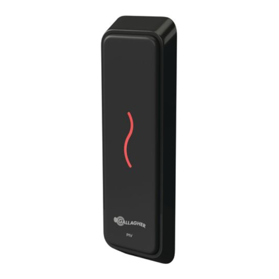
The Gallagher T10 Mifare Reader
The Gallagher T10 Mifare reader is a smart card proximity reader. It can
be installed as either an entry reader or exit reader.
The reader can read Mifare DESFire EV1, Mifare Plus and Mifare Classic
cards.
The reader sends information to the Cardax FT Controller and acts upon
information sent from the Cardax FT Controller. The reader itself does not
make any access decisions.
The Gallagher T10 Mifare reader uses the "Cardax IV Reader"
communications protocol to communicate with the Cardax FT Controller.
Gallagher T10 Mifare Reader
Installation Note | Gallagher T10 Mifare Reader
Installation Note
Part Number: 3E2453 R1 | 1
Advertisement
Table of Contents

Summary of Contents for Gallagher T10
- Page 1 The Gallagher T10 Mifare Reader The Gallagher T10 Mifare reader is a smart card proximity reader. It can be installed as either an entry reader or exit reader. The reader can read Mifare DESFire EV1, Mifare Plus and Mifare Classic cards.
-
Page 2: Before You Begin
2 x self tapping pan head pozi fixing screws Power Supply The Gallagher T10 Mifare reader receives power from the device to which it is connected. The reader is designed to operate over a supply voltage range of 9 - 16Vdc measured at the reader terminals. The operating current will be approximately 40mA (at 16Vdc) and 70mA (at 9Vdc). -
Page 3: Distance Between Proximity Readers
200mm (8 inches) away. Installation The Gallagher T10 Mifare reader is designed to be mounted on any solid flat surface. However installation on metal surfaces, particularly those with a large surface area will reduce read range. The extent to which the range is reduced will depend upon the type of metal used. - Page 4 Installation Note | Gallagher T10 Mifare Reader Using the drill template at the back of this installation note as a guide, drill all three holes. Drill the 13mm (1/2 inch) diameter centre hole (this is the centre hole for which the building cable will exit the mounting surface) and the two fixing holes.
- Page 5 Installation Note | Gallagher T10 Mifare Reader Insert the M3 Torx Post Security screw (using a T10 Torx Post Security screwdriver) through the hole at the bottom of the base to secure the facia assembly. Note: The recommended torque for the security screw is 0.7Nm (0.5 lb/ft).
- Page 6 Installation Note | Gallagher T10 Mifare Reader Connecting to the Cardax FT Reader Module (for the Controller 6000) Connect the wires to the sockets as shown: Positive Negative Black Reserved Orange Reserved Green Reserved Brown CDXIV TX White CDXIV RX...
- Page 7 Mifare readers into the Cardax FT Command Centre system. The Cardax FT Controller 3000-8R can interface up to eight Gallagher T10 Mifare readers into the Cardax FT Command Centre system. The ports to which the Gallagher T10 Mifare reader can connect are set up as groups, as follows: •...
- Page 8 Installation Note | Gallagher T10 Mifare Reader Make the connections from the Gallagher T10 Mifare reader to either the Cardax FT Controller 3000-4R or 3000-8R as shown: Cardax FT Controller 3000-4R or 3000-8R Group PB1 and PA1... to... PB2 and PA2 (3000-4R)
-
Page 9: Technical Specifications
Installation Note | Gallagher T10 Mifare Reader Technical Specifications Technical Specifications Routine maintenance Not applicable for this reader Cleaning This reader should only be cleaned with a clean, lint free, damp cloth Power required Voltage: 9Vdc - 16Vdc Current: 40mA (at 16Vdc) - Page 10 • Consult the dealer or an experienced radio/TV technician for help. Note: Changes or modifications not expressly approved by Gallagher Group Limited could void the user’s authority to operate this equipment. 10 | Part Number: 3E2453 R1...
-
Page 11: Drill Template
Drill Template 13mm (1/2 inch) diameter hole for cable 22.5mm (0.89 inches) 35mm (1.38 inches)


Need help?
Do you have a question about the T10 and is the answer not in the manual?
Questions and answers