Advertisement
ATTENTION: This equipment contains components that can be damaged
by electrostatic discharge. Ensure both you and the equipment are earthed
before beginning any servicing.
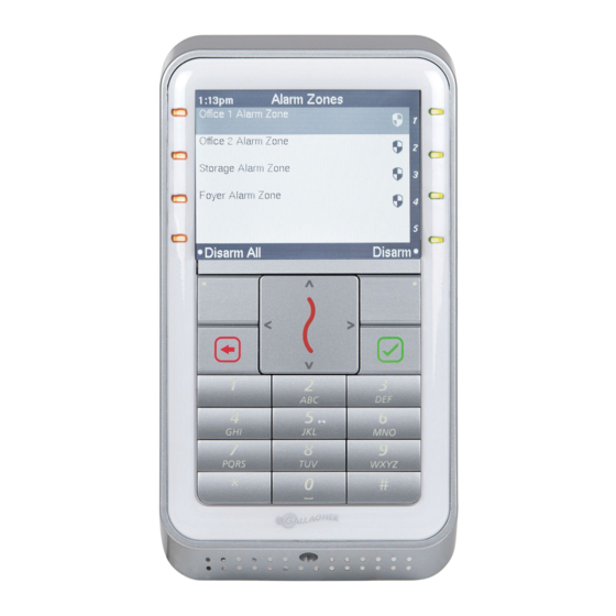
The Gallagher T20 Reader
The Gallagher T20 Reader is a smart card proximity reader. The reader can be
installed as either an entry reader or an exit reader.
The reader can be mounted on a rectangular 50 mm x 75 mm (2" x 3") flush box, BS
4662 British Standard square flush box, or any solid flat surface.
The Mifare reader reads: Mifare DESFire EV1, Mifare Plus and Mifare Classic cards.
The Multi Tech reader reads: Mifare DESFire EV1, Mifare Plus, Mifare Classic and 125
KHz cards.
The reader sends information to the Gallagher Controller and acts upon information
sent from the Gallagher Controller. The reader itself does not make any access
decisions.
The reader uses the Cardax IV communications protocol to communicate with the
Gallagher Controller. Refer to the "Connections" topic later in this note, for details
regarding Cardax IV Reader connections.
Document Code: 3E3140
Edition 3, April 2013
Installation Note
Gallagher T20 Reader
Page 1
Advertisement
Table of Contents

Subscribe to Our Youtube Channel
Related Manuals for Gallagher T20


Summary of Contents for Gallagher T20
- Page 1 The Gallagher T20 Reader The Gallagher T20 Reader is a smart card proximity reader. The reader can be installed as either an entry reader or an exit reader. The reader can be mounted on a rectangular 50 mm x 75 mm (2” x 3”) flush box, BS 4662 British Standard square flush box, or any solid flat surface.
-
Page 2: Before You Begin
1 x M3 Torx Post (T10) Security screw Power Supply The Gallagher T20 Reader is designed to operate over a supply voltage range of 9 - 16 Vdc measured at the reader terminals. The operating current draw is dependent on the supply voltage at the reader. For the Mifare reader, at 12 Vdc the current draw is 90 mA (standby). -
Page 3: Distance Between Proximity Readers
Installation Note Gallagher T20 Reader Single reader Single reader connected connected using using data only power and data Cable type Cable format* in a single cable in a single cable CAT 5e or better 4 twisted pair 200 m (650 ft) 100 m (330 ft) Each 2 x 0.2 mm... -
Page 4: Installation
Gallagher T20 Reader Installation Note Installation The Gallagher T20 Reader can be mounted on: • a vertical, rectangular 50 mm x 75 mm (2” x 3”) flush box • a BS 4662 British Standard square flush box • any solid flat surface The recommended mounting height for the reader is 1.1 m (3.6 ft) from the floor... - Page 5 Installation Note Gallagher T20 Reader Secure the tamper tab (located in the base) to the mounting surface using remaining fixing screw provided. No. 6 pan head screw Base Tamper tab Building cable Connect the reader tail extending from the facia assembly to the building cable.
- Page 6 Connections The Gallagher T20 Reader can be connected as a Cardax IV Reader to one of the following devices: • Gallagher Reader Module 8R or 4R (attached to the Controller 6000) •...
- Page 7 Installation Note Gallagher T20 Reader Gallagher Reader Module 8R or 4R (attached to the Controller 6000) Connect the wires to the sockets as shown: Negative Black Gallagher Reader Module Positive Reserved Orange Reserved Green Reserved Brown CDXIV RX Blue CDXIV TX...
- Page 8 Gallagher T20 Reader Installation Note Gallagher Controller 3000-8R or 3000-4R The ports to which the Gallagher T20 Reader can connect are set up as groups: • Four groups (numbered 1 to 4) on the Controller 3000-8R, and • Two groups (numbered 1 and 2) on the Controller 3000-4R Each group provides connection for two readers.
- Page 9 Installation Note Gallagher T20 Reader Make the connections from the reader to either the Controller 3000-8R or 3000-4R as shown: Gallagher Controller 3000-8R or 3000-4R Group PB1 and PA1... to... PB4 and PA4 (3000-8R) PB2 and PA2 (3000-4R) Cardax IV Reader Cardax IV Reader Note: Within each group, you cannot mix Cardax IV Readers with Wiegand Readers.
-
Page 10: Diagnostic Indication
Gallagher T20 Reader Installation Note HBUS LED Diagnostic Indications Diagnostic Indication 3 Flash (Amber) No communications with the Controller. On (Green or Red) Fully configured and functioning normally Green = Access mode is Free = Access mode is Secure Technical Specifications Routine maintenance: Not applicable for this reader. - Page 11 Installation Note Gallagher T20 Reader Icons The Gallagher T20 Reader displays the following icons: Arming Failed Arming Succeeded Armed Present Card Present Second Card Enter PIN Access Granted Access Denied Wrong PIN Free Access Document Code: 3E3140 Page 11 Edition 3, April 2013...
-
Page 12: Approvals And Standards
(2) this device must accept any interference received, including interference that may cause undesired operation. Note: Changes or modifications not expressly approved by Gallagher Limited could void the user’s authority to operate this equipment. Note: This equipment has been tested and found to comply with the limits for a Class B digital device, pursuant to part 15 of the FCC Rules. -
Page 13: Mounting Dimensions
Installation Note Gallagher T20 Reader Mounting Dimensions 95.7 mm (3.77 inches) 6G Screw 29.1 mm (1.14 inches) 125 card read area 60.3 mm (2.37 inches) Flush Box Screw Cable Exit Mifare card read area IMPORTANT This picture is not to scale, therefore use the measurements provided.
Need help?
Do you have a question about the T20 and is the answer not in the manual?
Questions and answers