Table of Contents
Advertisement
Advertisement
Table of Contents

Related Manuals for MINN KOTA Ultrex 1368800


Summary of Contents for MINN KOTA Ultrex 1368800
- Page 1 ULTREX™ BOW-MOUNT TROLLING MOTOR OWNER'S MANUAL...
-
Page 2: Serial Number
Countless hours of research and testing provide you the Minn Kota advantage that can truly take you “Anywhere. Anytime.” We don’t believe in shortcuts. We are Minn Kota. And we are never done helping you catch more fish. - Page 3 WARNING You are responsible for the safe and prudent operation of your vessel. We have designed your Minn Kota product to be an accurate and reliable tool that will enhance boat operation and improve your ability to catch fish. This product does not relieve you from the responsibility for safe operation of your boat.
- Page 4 KNOW YOUR BOAT Port Starboard Inboard Outboard Keel Port Starboard Gunwale Transom Stern Gunwale Stern Hull...
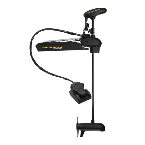
- Page 5 FEATURES i-Pilot/ i-Pilot Link Control Pull Grip and Cable Mono-Arm Depth Collar Knob Steering Module Lift-Assist Momentary On Button Speed Control Lifetime Warranty Flexible Composite Shaft Power Switch Spot-Lock AutoPilot Heel Block Constant High-Impact Indicator Panel On Button Composite Material Power AutoPilot Cool Quiet...
- Page 6 Your new Ultrex comes with everything you’ll need to directly install it to the boat. This motor can be directly mounted to the boat or coupled with a Minn Kota quick release bracket for ease of mounting and removal. For installation with a quick release bracket, refer to the installation instructions provided with the bracket.
- Page 7 ASSEMBLY OF MOTOR TO MOUNT MOUNTING CONSIDERATIONS It is recommended that the motor be mounted as close to the keel or centerline of the boat as possible. Make sure the area under the mounting location is clear to drill holes and install nuts and washers. Make sure the motor rest is positioned far enough beyond the edge of the boat.
- Page 8 INSTALLING THE BOW-MOUNT e. Reinstall the 5/16" Allen Screw and Lock Washer Allen Screw with and tighten to 18 to 20 ft-lbs with a Torque Lock Washer Wrench. NOTE: The 5/16" Allen Screw must be tightened when installed and periodically tightened to 18 to 20 ft-lbs.
- Page 9 INSTALLING THE BOW-MOUNT c. The Mount can be installed on either the Port or Starboard side of the boat based on personal preference. Test the placement of the Hold-Down Strap to be sure it can hold the Mount as placed. The placement of the buckle on the Hold-Down Strap either inboard or outboard is based on Deck of Boat...
- Page 10 INSTALLING THE GAS SPRING PIN ITEM(S) NEEDED #4 x 6 #5 x 6 #6 x 6 Put a 1/4-20 x 3 1/2" Screw (Item #4) in each Screw of the drilled locations. The Screw should pass through the Mount Plate and the boat deck. k.
- Page 11 INDEXING THE MOTOR ITEM(S) NEEDED #26 x 2 #25 x 2 #27 x 1 c. Locate the upper Gas Spring Pin (Item #27) and Gas Spring Phillips Screw Spacers (Item #26) in the bag assembly. Align the end Cylinder Outer Arm of the Gas Spring with the holes in the Outer Arm.
- Page 12 INDEXING THE MOTOR a. Turn the Power Switch "on" and steer the motor so that the Control Head is in line with the keel of Control Head the boat. This can be done by steering the motor with the Foot Pedal, turning the motor with Pedal Control the remote, or manually turning the head of the Sleeve Assembly...
- Page 13 INDEXING THE MOTOR e. Remove the two screws that hold the Wrap Drum Steering Screws Steering Motor Cover in place with a #1 Phillips Screwdriver. Module Connection Plug Steering Motor Once removed, lift the Wrap Drum Cover away Connection Plug from the Steering Module.
- Page 14 INDEXING THE MOTOR h. While holding the Wrap Drum just above the Steering Steering Motor Wrap Drum Cable Gear, and maintaining tension on the Module Connection Wire Steering Cables, carefully rotate the Wrap Drum right or left until the top of the Foot Pedal is parallel with the deck of the boat.
- Page 15 INDEXING THE MOTOR k. Reconfirm that the Steering Cables are tight Wrap Drum Cover and then carefully thread the Steering Motor Steering Motor Connection Wire through the top of the Wrap Connection Wire Drum Cover. The male plug comes from the Cable Anchor through the opening at the bottom of the Wrap Drum Cover.
- Page 16 ORIENTATE THE PEDAL CONTROL SLEEVE ASSEMBLY FOR A STARBOARD MOUNT Orientate the Pedal Control Sleeve Assembly for a Starboard Mount By default, the Pedal Control Sleeve Assembly is factory set so that when your Ultrex is installed on the port side of your boat, the Pedal Control Sleeve Assembly points inboard.
- Page 17 ORIENTATE THE PEDAL CONTROL SLEEVE ASSEMBLY FOR A STARBOARD MOUNT c. Remove the Connector Cover from the Wrap Flat Drum Cover using a 1/8” wide Flat Screwdriver Screwdriver to release it. Release it by pressing the flat part of the screwdriver in the slot closest to the center of the Connector Cover and prying upwards.
- Page 18 ORIENTATE THE PEDAL CONTROL SLEEVE ASSEMBLY FOR A STARBOARD MOUNT g. The Cable Anchor functions to hold the Steering Cables in place. The cables run from the Cable Anchor and wrap around the Wrap Drum. The Cable Anchor is secured to the Steering Module with two screws.
- Page 19 ORIENTATE THE PEDAL CONTROL SLEEVE ASSEMBLY FOR A STARBOARD MOUNT Secure the Cable Anchor to the inboard side Screws Steering of the Steering Module by loosely securing the Module screws in place using a #2 Phillips screwdriver. k. Once the Cable Anchor is secured, finish prying the Wrap Drum straight up, off...
- Page 20 ORIENTATE THE PEDAL CONTROL SLEEVE ASSEMBLY FOR A STARBOARD MOUNT n. Re-tighten the two screws that fasten the Cable Screws Steering Anchor to the top of the Steering Module using a Module #2 Phillips screwdriver. Tighten to 25 in-lbs. Cable Anchor o.
- Page 21 PLACING THE BOW-MOUNT STABILIZER Reconnect the Steering Motor Connection Plug and push it into the Wrap Drum Cover. UTION Steering Motor Connection Plug Wires and plug must not touch moving parts. Wires may be damaged if caught in moving parts. s.
- Page 22 PLACING THE BOW-MOUNT STABILIZER ITEM(S) NEEDED #17 x 2 #18 x 2 c. Determine the desired orientation of the Steering Module Stabilizer Bracket and attach it to the bottom of the Steering Module. Place a Lock Washer (Item Lock Washer and Cap Screw #18) on each of the two 5/16"...
- Page 23 MOUNTING THE FOOT PEDAL h. Replace the Bottom Bumper on the Aluminum Stabilizer Bracket Rod, opposite from the threads. Thread the Aluminum Rod into the Stabilizer Bracket with the Bottom Bumper towards the Jam Nut boat deck. Adjust the Aluminum Rod up or down in the Stabilizer Bracket so that the Bottom Bumper Aluminum Rod just touches the support surface.
- Page 24 CONNECTING UNIVERSAL SONAR Connecting Universal Sonar Your trolling motor is pre-installed with a Universal Sonar transducer system. Universal Sonar is a 2D sonar transducer with a temperature sensor that is integrated into the lower unit of the trolling motor. It has an operating frequency of 83/200 kHz. Connecting this transducer to a compatible fish finder* gives you a 2D sonar view of what is happening directly below your trolling motor.
- Page 25 Universal Sonar. If two cables are present, one is to connect the Universal Sonar, and the other is to connect the i-Pilot Link connection. Please follow the Minn Kota recommendations on routing the cables to optimize mobility and maximize functionality.
- Page 26 ROUTING UNIVERSAL SONAR & -PILOT LINK CABLES ITEM(S) NEEDED #24 x 1 a. Place the motor in the stowed position. b. Locate the Universal Sonar and i-Pilot Link Control Head Cable Connection, if equipped, at the base of the Control Head. Universal i-Pilot Link Cable Sonar...
- Page 27 ROUTING UNIVERSAL SONAR & -PILOT LINK CABLES d. Grasp the opposite ends of the extension cables for the Universal Sonar, and i-Pilot Link, if Tie Wrap Cable Placement equipped. Control Head Universal e. Start at the top of the Coil Cord, where it is Sonar Universal Sonar...
- Page 28 REMOVAL OF THE STEERING MODULE Removal of the Steering Module A. DISCONNECT THE GAS SPRING WARNING Moving parts can cut or crush. The gas assist lift mechanism is under pressure. Disconnect gas spring before removing motor from mount. Do not engage the Pull Grip and Cable until gas spring is disconnected.
- Page 29 REMOVAL OF THE STEERING MODULE d. Once the screws are removed, the pin and Outer Arm spacers can be removed from the Upper Cylinder. e. Now it is safe to move the motor into the deployed position. Gas Spring Cylinder Outer Arm B.
- Page 30 REMOVAL OF THE STEERING MODULE d. Reinstall the 5/16" Allen Screw and Lock Washer Allen Screw with Lock Washer and tighten to 18 to 20 ft-lbs with a Torque Wrench. e. Position the motor to the stowed position using the Pull Grip and Cable to disengage the latch bar, allowing the motor to fold into a flat position.
-
Page 31: Conductor Gauge And Circuit Breaker Sizing Table
UTION These guidelines apply to general rigging to support your Minn Kota motor. Powering multiple motors or additional electrical devices from the same power circuit may impact the recommended conductor gauge and circuit breaker size. If you are using wire longer than that provided with your unit, follow the conductor gauge and circuit breaker sizing table below. - Page 32 Minn Kota recommends using Minn Kota brand chargers to recharge the batteries connected to your Minn Kota trolling motor, as they have been engineered to work with motors that include a bonding wire.
- Page 33 CONNECTING THE BATTERIES IN SERIES The negative (-) connection must be connected to the negative terminal of the same battery that the trolling motor negative lead connects to. In the diagrams below this battery is labeled “Low Side” Battery. Connecting to any other trolling motor battery will input positive voltage into the “ground”...
- Page 34 CONNECTING THE BATTERIES IN SERIES 36 Volt Systems Three 12 volt batteries are required. The batteries must be wired in series, only as directed in wiring diagram, to provide 36 volts. 1. Make sure that the motor is switched +36 Volts to trolling motor off...
-
Page 35: Motor Wiring Diagram
MOTOR WIRING DIAGRAM Speed Adjustment Switch Brown Fuse Ground Black M- Accessory Power Brown Attachment Switch Control Head Red M+ Indicator Lights Momentary Control Coil Cord Universal Steer Right/ Black Sonar* End of Limit White Switch White Steer Left/ End of Limit Switch Accessory Attachment... - Page 36 USING & ADJUSTING THE MOTOR MOUNT FEATURES Become familiar with the features of the motor to maximize the capabilities this product offers. Pull Grip and Cable Mount Ramp Yoke Motor Shaft Motor Mount Lower Unit Motor Rest Hold-Down Strap Motor Mount The Motor Mount is designed to securely hold the motor in place on the deck of the boat.
- Page 37 ADJUSTING THE LOWER UNIT FOR A SECURE STOW STOWING AND DEPLOYING THE MOTOR To Deploy the Motor WARNING Make sure that the Hold-Down Strap is not secured and then simply pull back and lift the motor off of the mount with When stowing or deploying the motor, keep fingers clear of all the Pull Grip and Cable.
- Page 38 ADJUSTING THE DEPTH OF THE MOTOR c. With the motor in the deployed position, firmly Shaft Shaft grasp the motor Shaft above the Steering Depth Collar Depth Depth Module. Collar Collar Knob Knob d. Locate the Depth Collar on the Shaft. Loosen the Depth Collar Knob, while holding the Shaft in place, until the Shaft slides freely.
- Page 39 ADJUSTING THE PULL GRIP AND CABLE Adjusting the Pull Grip and Cable The length of the Cable on the Pull Grip and Cable can be adjusted based on personal preference. Before beginning the adjustment, the Gas Spring Pin must be disengaged, and the Steering Module must be removed. Please refer to the Removal of the Stering Module section and follow the procedure to Disconnect the Gas Spring Pin and Remove Motor from Mount.
- Page 40 ADJUSTING THE PULL GRIP AND CABLE c. Grasp the Pull Cable Clamp and Cable and pull it Set Screw out of the Aluminum Arm. Cable Adjust Cable d. The Pull Cable Clamp contains two Set Screws. Cable Loosen, but do not remove, these two screws with a 5/64 Allen Wrench until the Cable can slide in the Pull Cable Clamp.
- Page 41 The foot pedal is used to operate the motor, and controls on the foot pedal are easy to operate by either foot or hand. The motor can also be controlled by an i-Pilot or i-Pilot Link remote, as well as any compatible Minn Kota remote. Please refer to the i-Pilot, i-Pilot Link or compatible remote manual on how the remote controls the motor.
- Page 42 CONTROLLING SPEED & STEERING WITH THE FOOT PEDAL If a propeller encounters an obstruction while either in Momentary or Constant Mode, while the propeller is running, the increased electrical current being generated by the obstruction will signal the motor to decrease the power to the propeller to prevent damage.
- Page 43 When steering the Ultrex with either the foot pedal or compatible NOTE: The motor will not auto correct to drive Minn Kota remote, the Steering Lock feature will automatically straight when it encounters an obstruction. lock the motor in the last position that was specified, allowing the operator to remove their foot from the pedal or hand from the remote and remain traveling in their chosen direction.
-
Page 44: Propeller Replacement
SERVICE & MAINTENANCE PROPELLER REPLACEMENT TOOLS AND RESOURCES REQUIRED • 9/16” Open End Wrench • Flat Blade Screwdriver INSTALLATION a. Disconnect the motor from all sources of power prior to changing the propeller. Drive Pin Armature Shaft b. Hold the propeller and loosen the Prop Nut with a pliers or a wrench. -
Page 45: General Maintenance
SERVICE & MAINTAINANCE GENERAL MAINTENANCE • After use, the entire motor should be rinsed with freshwater. This series of motors is not equipped for saltwater exposure. • The composite shaft requires periodic cleaning and lubrication for proper retraction and deployment. A coating of an aqueous based silicone spray will improve operation. -
Page 46: Compliance Statements
Minn Kota motors are not subject to the disposal regulations EAG-VO (electric devices directive) that implements the WEEE directive. Nevertheless never dispose of your Minn Kota motor in a garbage bin but at the proper place of collection of your local town council. - Page 47 FCC COMPLIANCE FCC COMPLIANCE This device complies with Part 15 of the FCC rules. Operation is subject to the following two conditions: This device may not cause harmful interference. 2. This device must accept any interference that may be received, including interference that may cause undesired operation. Changes or modifi...
- Page 48 80/112 LBS THRUST - 24/36 VOLT - 45”/52”/60” SHAFT The parts diagram and parts list provides Minn Kota® WEEE compliance disassembly instructions. For more information about where you should dispose of your waste equipment for recycling and recovery and/or your European Union member state requirements, please contact your dealer or distributor from which your product was purchased.
- Page 49 PARTS DIAGRAM & PARTS LIST Motor Parts List Assembly Part # Description Quantity 2777095 CTR HSG ASY, CB 80#, FW 60" TUBE CTR HSG ASY, CB 112#, FW, 60" TUBE 2777243 80#/45" 24V MOTOR US2 *MOTOR & TUBE* 2777005 80#/52" 24V MOTOR US2 *MOTOR & TUBE* 2777003 MTR/TUBE ASSY 80# 60"...
- Page 50 PARTS DIAGRAM & PARTS LIST Item Part # Description Quantity 2333101 NUT-HEX #10-24 UNC-2B NYL SS 880-025 SEAL 725-095 PAPER TUBE, SEAL 92-300-170 BRUSH END HSG, 80# 144-017 BEARING, FLANGE 830-095 THRU BOLT 12-24 990-052 WASHER, NYLATRON 990-051 WASHER-STEEL THRUST 973-025 SPACER, BRUSHPLATE 9-738-015...
- Page 51 PARTS DIAGRAM & PARTS LIST Item Part # Description Quantity 140-014 BEARING - BALL 992-011 WASHER, SPRING BELLEVILLE 990-011 WASHER, SHIM PLN END HSG 4.5" US2.5 PNT FW ✖ 582-013 CLIP, RETAINING SHORT 640-117 MOTOR WIRE, RED, 80#, 45" 640-132 MOTOR WIRE, RED, 80#, 52"...
- Page 52 PARTS DIAGRAM & PARTS LIST ULTREX STEERING MODULE Steering Module Parts Diagram...
- Page 53 PARTS DIAGRAM & PARTS LIST Steering Module Parts List Assembly Part # Description Quantity 2991896 STEERING MODULE ASSEMBLY FW 2991925 BRACK ABLZR ARM Y (SUB) Item Part # Description Quantity ✖ SEAL ✖ HOUSING, UPPER, PAINTED ✖ BUSHING-1012-08 ✖ SCREW-M4 X 8MM, FHP, SS ✖...
- Page 54 PARTS DIAGRAM & PARTS LIST ULTREX FOOT PEDAL Foot Pedal Parts Diagram 256 362...
- Page 55 PARTS DIAGRAM & PARTS LIST Foot Pedal Parts List Assembly Part # Description Quantity 36V FOOT PEDAL ASSEMBLY 2992155 2992150 24V FOOT PEDAL ASSEMBLY FT PED CABLE, WIRE HARNESS, ASM 2771200 CONTROL BOARD KIT, 36V ULTREX 2774061 2774060 CONTROL BOARD KIT, 24V ULTREX Item Part # Description...
- Page 56 PARTS DIAGRAM & PARTS LIST Item Part # Description Quantity 2223455 SCREW-#10-32 X 1/2" ZP MACHINE 2993735 ARM-SENSOR, AP W/MAGN 2993725 ARM-SENSOR, SL W/MAGN 2994500 E W/PIN, FOOT PEDAL 2365107 INSU TING PAD(2.3 X 3.2) 2263210 BRACK -CONDUIT ADJU MEN [B060 2263140 KEEPER-NYLOCK 2263466...
- Page 57 PARTS DIAGRAM & PARTS LIST ULTREX MOUNT Mount Parts Diagram...
- Page 58 PARTS DIAGRAM & PARTS LIST Mount Parts List Assembly Part # Description Quantity 2991733 MOUNT M ULTREX FW 112# 45" 2991734 MOUNT M ULTREX FW 80# 45" 2991735 MOUNT M ULTREX FW 80# 52/60" 2991736 MOUNT M ULTREX FW 112# 52/60" 2994912 BAG ASSY, FORTREX MOUNT HDW 2994887...
- Page 59 PARTS DIAGRAM & PARTS LIST Item Part # Description Quantity 2288403 SPRING (CYLINDER) (SUB) 2288404 SPRING (CYLINDER) 80# 45" 52/60" 2288405 SPRING (CYLINDER) 112# 45" 2282604 PIN-KNURLED 5/16"X2 1/4"SS 2283615 TCH BAR 2373450 SCREW-#8-18 X 3/8" THRD.CUT SS 2261732 HER-#8, NYLON 2283610 BRACK - TCH/ RAP,ROPE PULL 2283601...
- Page 60 PARTS DIAGRAM & PARTS LIST Item Part # Description Quantity 2285803 HANG TAG, WARNING, FORTREX 2263468 1/4 - 20 X 2.5" SS PPH SCREW 2263103 1/4 - 20 SS NYLOCK NUT 2261713 1/4 F T 18-8 SS W 2283631 RAIL, MACH, MOTOR R *A ER Q306MK00001* 2323403 SCREW - 1/4 - 20 X 1/2"...
- Page 61 Stop buying new batteries and start taking care of the ones you’ve got. Many chargers can actually damage your battery over time – creating shorter run times and shorter overall life. Digitally controlled Minn Kota chargers are designed to provide the fastest charge that protect and extend battery life.
Need help?
Do you have a question about the Ultrex 1368800 and is the answer not in the manual?
Questions and answers