Table of Contents
Advertisement
Quick Links
Advertisement
Table of Contents

Related Manuals for Supermicro X11DDW-L/NT


Summary of Contents for Supermicro X11DDW-L/NT
- Page 1 X11DDW-L/NT USER’S MANUAL Revision 1.0a...
- Page 2 State of California, USA. The State of California, County of Santa Clara shall be the exclusive venue for the resolution of any such disputes. Supermicro's total liability for all claims will not exceed the price paid for the hardware product.
-
Page 3: About This Manual
Intel Intelligent Power Node Manager, Active Management Technology, and vPro technology. The X11DDW-L/NT includes four NVMe connectors, slots for riser card support, fourteen SATA 3.0 ports, and dual LAN and USB 3.0 ports. The X11DDW-L/NT provides maximum performance, system cooling, and PCI-E capacity. This motherboard is optimized for PCI- Express expansion with flexible IO support, and is ideal for general-purpose server platforms. -
Page 4: Contacting Supermicro
X11DDW-L/NT User's Manual Contacting Supermicro Headquarters Address: Super Micro Computer, Inc. 980 Rock Ave. San Jose, CA 95131 U.S.A. Tel: +1 (408) 503-8000 Fax: +1 (408) 503-8008 Email: marketing@supermicro.com (General Information) support@supermicro.com (Technical Support) Website: www.supermicro.com Europe Address: Super Micro Computer B.V. -
Page 5: Table Of Contents
Preface Table of Contents Chapter 1 Introduction 1.1 Checklist ..........................8 Quick Reference .......................11 Quick Reference Table ......................12 Motherboard Features .......................14 1.2 Processor and Chipset Overview ..................18 1.3 Special Features ........................18 Recovery from AC Power Loss ..................18 1.4 System Health Monitoring ....................19 Onboard Voltage Monitors ....................19 Fan Status Monitor with Firmware Control ...............19 Environmental Temperature Control .................19... - Page 6 X11DDW-L/NT User's Manual Preparing the CPU Socket for Installation ................28 Removing the Dust Cover from the CPU Socket .............28 Attaching the Processor to the CPU/Heatsink Carrier ............29 Attaching the CPU/Carrier Assembly to the Passive Heatsink to Form the Processor Heatsink Module (PHM) ....................30 Installing the Processor Heatsink Module (PHM) ............31...
- Page 7 Battery Removal ........................72 Proper Battery Disposal ....................72 Battery Installation ......................72 3.5 Returning Merchandise for Service ..................73 Chapter 4 BIOS 4.1 Introduction .........................74 4.2 Main Setup .........................75 4.3 Advanced Setup Configurations ..................77 4.4 Event Logs ........................105 4.5 IPMI ...........................107 4.6 Security ...........................110 4.7 Boot ..........................114 4.8 Save &...
-
Page 8: Chapter 1 Introduction
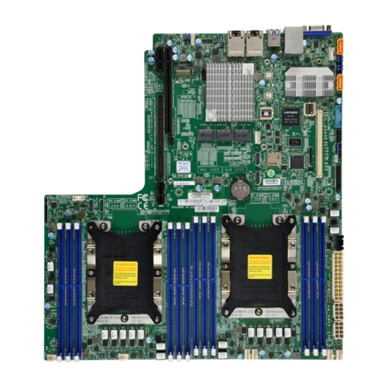
Introduction Congratulations on purchasing your computer motherboard from an industry leader. Supermicro motherboards are designed to provide you with the highest standards in quality and performance. In addition to the motherboard, several important parts that are included with your shipment are listed below. - Page 9 Chapter 1: Introduction Figure 1-1. Motherboard Image Lorem ipsum Note: All graphics shown in this manual were based upon the latest PCB revision available at the time of publication of the manual. The motherboard you received may or may not look exactly the same as the graphics shown in this manual.
- Page 10 X11DDW-L/NT User's Manual Figure 1-2. X11DDW-L Motherboard Layout (not drawn to scale) JUIDB1 USB2/3 (3.0) LAN2 LAN1 IPMI_LAN USB0/1(3.0) JM2_1 10G PHY C621 JSTBY1 S-SATA 0~3 I-SATA 0~3 I-SATA 4~7 JBT1 LEDM1 S-SGPIO2 SRW1 BIOS LICENSE MAC CODE BAR CODE...
-
Page 11: Quick Reference
Chapter 1: Introduction Quick Reference IPMI LAN USB0/1 LAN1 JUIDB1 JPME1 LAN2 USB2/3 JPME2 JUIDB1 S-SATA5 JIPMB1 USB2/3 JSXB1_1 (3.0) JPG1 LAN2 LAN1 IPMI_LAN JPL1 USB0/1(3.0) JM2_1 JBR1 CPU2 PCI-E 3.0 X16 JM2_1 JWD1 10G PHY S-SATA4 C621 JSTBY1 I-SATA4~7 JSTBY1 I-SATA0~3 USB4/5... -
Page 12: Quick Reference Table
(I-)SATA0~3, 4~7 I- SATA 3.0 connectors supported by the Intel PCH (S-)SATA0~3 S-SATA 3.0 connectors supported by the Intel SCU S-SATA connectors with built-in power pins and support of Supermicro SuperDOM (Disk-on (S-)SATA4/S-SATA5 Module) devices SXB1 PCI-E 3.0 (x16 + x16) Left Riser Card slot supported by CPU1 and CPU2... - Page 13 Chapter 1: Introduction Connector Description SXB2 PCI-E 3.0 x16 Right Riser Card slot supported by CPU2 S-SGPIO2 Serial General Purpose I/O port USB0/1 Back panel USB 3.0 ports USB2/3 Back panel USB 3.0 ports USB4/5 USB 3.0 headers Back panel VGA port Description Status UID (Unit Identifier) LED...
-
Page 14: Motherboard Features
DIMM Size • Up to 128GB at 1.2V Note 1: Memory speed support depends on the processors used in the system. Note 2: For the latest CPU/memory updates, please refer to our website at http://www.supermicro.com/products/ motherboard. Chipset • Intel C621 (-L) •... - Page 15 • Power-on mode for AC power recovery • Intel® Intelligent Power Node Manager 3.0 (available when the Supermicro Power Manager [SPM] is installed and a special power supply is used. See the note on page 20.) • Management Engine (ME) System Health Monitoring •...
- Page 16 User's Guide available at http://www.supermicro.com/support/manuals/. Note 3: It is strongly recommended that you change BMC log-in information upon initial system power-on. The manufacture default username is ADMIN and the password is ADMIN. For proper BMC configuration, please refer to http://www.supermicro.com/ products/info/files/IPMI/Best_Practices_BMC_Security.pdf...
-
Page 17: System Block Diagram
Chapter 1: Introduction Figure 1-3. System Block Diagram VCCP0 12v VCCP1 12v #F-0 #M-0 VR13 VR13 #E-0 #L-0 5+1 PHASE 5+1 PHASE #D-0 #K-0 205W #C-0 #J-0 205W 10.4/11.2G #B-0 #H-0 #A-0 #G-0 VCCP0-(F) VCCP1 CPU1 CPU2 PECI : 30 PECI : 31 SOCKET ID : 0 SOCKET ID : 1... -
Page 18: Processor And Chipset Overview
With features like a 6-channel DDR4 memory controller and up to 28 cores with Hyper-Threading technology, the X11DDW-L/NT provides maximum performance, system cooling, and PCI-E capacity. This motherboard is optimized for general purpose server platforms. -
Page 19: System Health Monitoring
The default setting is Last State. 1.4 System Health Monitoring This section describes the health monitoring features of the X11DDW-L/NT motherboard. The motherboard has an onboard Baseboard Management Controller (BMC) chip that supports system health monitoring. Once a voltage becomes unstable, a warning is given or an error message is sent to the screen. -
Page 20: Acpi Features
X11DDW-L/NT User's Manual 1.5 ACPI Features ACPI stands for Advanced Configuration and Power Interface. The ACPI specification defines a flexible and abstract hardware interface that provides a standard way to integrate power management features throughout a computer system including its hardware, operating system and application software. -
Page 21: Advanced Power Management
Intelligent Power Node Manager (IPNM) ® Available when the Supermicro Power Manager (SPM) is installed, Intel's Intelligent Power Node Manager (IPNM) provides your system with real-time thermal control and power management for maximum energy efficiency. Although IPNM Specification Version 2.0/3.0 is supported by the BMC (Baseboard Management Controller), your system must also have IPNM-compatible Management Engine (ME) firmware installed to use this feature. -
Page 22: Chapter 2 Installation
X11DDW-L/NT User's Manual Chapter 2 Installation 2.1 Static-Sensitive Devices Electrostatic Discharge (ESD) can damage electronic com ponents. To avoid damaging your motherboard and your system, it is important to handle it very carefully. The following measures are generally sufficient to protect your equipment from ESD. -
Page 23: Motherboard Installation
Chapter 2: Installation 2.2 Motherboard Installation All motherboards have standard mounting holes to fit different types of chassis. Make sure that the locations of all the mounting holes for both the motherboard and the chassis match. Although a chassis may have both plastic and metal mounting fasteners, metal ones are highly recommended because they ground the motherboard to the chassis. -
Page 24: Installing The Motherboard
X11DDW-L/NT User's Manual Installing the Motherboard 1. Install the I/O shield into the back of the chassis. 2. Locate the mounting holes on the motherboard. See the previous page for the location. 3. Locate the matching mounting holes on the chassis. Align the mounting holes on the motherboard against the mounting holes on the chassis. -
Page 25: Processor And Heatsink Installation
When receiving a motherboard without a processor pre-installed, make sure that the plastic CPU socket cap is in place and none of the socket pins are bent; otherwise, contact your retailer immediately. • Refer to the Supermicro website for updates on CPU support. The Processor 81xx/61xx/51xx/41xx/31xx (The Processor) Note: All graphics, drawings and pictures shown in this manual are for illustration only. -
Page 26: Overview Of The Processor Socket Assembly
X11DDW-L/NT User's Manual Overview of the Processor Socket Assembly The processor socket assembly contains 1) the 81/xx/61xx/51xx/41xx/31xx processor, 2) CPU/heatsink carrier, 3) dust cover, and 4) CPU socket. 81xx/61xx/51xx/41xx/31xx Processor 2. CPU/Heatsink Carrier 3. Dust Cover 4. CPU Socket CPU Socket Assembly Note: Be sure to cover the CPU socket with the dust cover when the CPU is not in- stalled. -
Page 27: Overview Of The Processor Heatsink Module
Chapter 2: Installation Overview of the Processor Heatsink Module The processor heatsink module (PHM) contains 1) a passive heatsink, 2) a CPU/heatsink carrier, and 3) the 81/xx/61xx/51xx/41xx/31xx processor. 1. Passive Heatsink 2. CPU/Heatsink Carrier 81/xx/61xx/51xx/41xx/31xx processor Processor Heatsink Module (Bottom View) -
Page 28: Preparing The Cpu Socket For Installation
X11DDW-L/NT User's Manual Preparing the CPU Socket for Installation This motherboard comes with the CPU socket pre-assembled in the factory. The CPU socket contains 1) a dust cover, 2) a socket bracket, 3) the CPU (LGA3647) socket, and 4) a back plate. -
Page 29: Attaching The Processor To The Cpu/Heatsink Carrier
Chapter 2: Installation Attaching the Processor to the CPU/Heatsink Carrier To properly install the CPU onto the CPU/heatsink carrier, please follow the steps below. 1. Locate Pin 1 (Notch A), Notch B, and Notch C on the CPU and locate Pin 1 (Notch A), Notch B, and Notch C on the CPU/heatsink carrier. -
Page 30: Attaching The Cpu/Carrier Assembly To The Passive Heatsink To Form The Processor Heatsink Module (Phm)
X11DDW-L/NT User's Manual Attaching the CPU/Carrier Assembly to the Passive Heatsink to Form the Processor Heatsink Module (PHM) After you have made a CPU/carrier assembly, please follow the steps below to mount the assembly onto the heatsink to create the Processor Heatsink Module (PHM). -
Page 31: Installing The Processor Heatsink Module (Phm)
Chapter 2: Installation Installing the Processor Heatsink Module (PHM) 1. Once you have assembled the processor heatsink module (PHM) by following the instructions listed on the previous page, align the processor heatsink module with the CPU socket on the motherboard. 2. -
Page 32: Removing The Processor Heatsink Module (Phm)
X11DDW-L/NT User's Manual Removing the Processor Heatsink Module (PHM) Before starting to remove the processor heatsink module (PHM), unplug power cord from the power outlet. 1. Using a T30-size star driver, turn the screws on the PHM counterclockwise to loosen it from the socket, starting with screw marked #4 (in the sequence of 4, 3, 2, 1). -
Page 33: Memory Support And Installation
Memory Support The X11DDW-L/NT supports up to 1536GB of Load Reduced DIMM (LRDIMM), Registered DIMM (RDIMM), and Non-Volatile DIMM (NV-DIMM) DDR4 (288-pin) ECC 2666MT/s modules in 12 slots. Populating these DIMM modules with a pair of memory modules of the same type and size will result in interleaved memory, which will improve memory performance. -
Page 34: Dimm Population Requirements
X11DDW-L/NT User's Manual DIMM Population Requirements For optimal memory performance, follow the tables below when populating memory modules. Key Parameters for DIMM Configurations Parameters Possible Values Number of Channels 1, 2, 3, 4, 5, or 6 Number of DIMMs per Channel... - Page 35 Chapter 2: Installation DDR4 Only Socket Level Population Requirements DDR4 Socket Level Minimum Population Requirements • There should be at least one DDR4 DIMM per socket. • If only one DIMM is populated in a channel, then populate it in the slot furthest away from CPU. •...
- Page 36 X11DDW-L/NT User's Manual Purley DDR4 Only 2SPC Memory Configuration with x4 DIMMs Total # of DDR Channel Number Adaptive Virtual DIMMs of Ranks Lock Step DIMM Popula- 1 x4 DIMM Must be installed on iMC0 DDR Channel 0 Y, only Bank VLS tion within an >1...
-
Page 37: Dimm Installation
Chapter 2: Installation DIMM Installation JUIDB1 USB2/3 (3.0) LAN2 LAN1 1. Insert DIMM modules in the following IPMI_LAN USB0/1(3.0) JM2_1 10G PHY order: For CPU1, begin with P1-DIMMC1, C621 JSTBY1 P1-DIMMB1, P1-DIMMA1 then P1- S-SATA 0~3 I-SATA 0~3 I-SATA 4~7 JBT1 LEDM1 DIMMF1, P1-DIMME1, P1-DIMMD1. -
Page 38: Rear I/O Ports
X11DDW-L/NT User's Manual 2.5 Rear I/O Ports See the figure below for the locations and descriptions of the various I/O ports on the rear of the motherboard. JUIDB1 USB2/3 (3.0) LAN2 LAN1 IPMI_LAN USB0/1(3.0) JM2_1 10G PHY C621 JSTBY1 S-SATA 0~3... - Page 39 Note: UID can also be triggered via IPMI on the motherboard. For more information on IPMI, please refer to the IPMI User's Guide posted on our website at http://www. supermicro.com. UID Switch UID LED...
-
Page 40: Usb Connection
X11DDW-L/NT User's Manual Universal Serial Bus (USB) Ports There are two USB 3.0 ports (USB0/1) and two USB 3.0 ports (USB2/3) on the I/O back panel. There is one USB 3.0 header (USB4/5) on the motherboard to provide front access USB connection. -
Page 41: Ethernet Ports
Chapter 2: Installation Ethernet Ports Two LAN ports (LAN1/LAN2) and a dedicated IPMI LAN are located on the I/O back panel. These LAN ports are supported by the onboard AST 2500 BMC and accepts an RJ45 type cable. Refer to the LED Indicator Section for LAN LED information. LAN Ports Pin Definition Pin#... -
Page 42: Front Control Panel
JF1 contains header pins for various buttons and indicators that are normally located on a control panel at the front of the chassis. These connectors are designed specifically for use with Supermicro chassis. See the figure below for the descriptions of the front control panel buttons and LED indicators. - Page 43 Chapter 2: Installation Power Button The Power Button connection is located on pins 1 and 2 of JF1. Momentarily contacting both pins will power on/off the system. This button can also be configured to function as a suspend button (with a setting in the BIOS - see Chapter 4). To turn off the power when the system is in suspend mode, press the button for 4 seconds or longer.
- Page 44 X11DDW-L/NT User's Manual Power Fail LED The Power Fail LED connection is located on pins 5 and 6 of JF1. Refer to the table below for pin definitions. Power Fail LED Pin Definitions (JF1) Pin# Definition 3.3V PWR Supply Fail...
- Page 45 Chapter 2: Installation NIC1/NIC2 (LAN1/LAN2) The NIC (Network Interface Controller) LED connection for LAN port 1 is located on pins 11 and 12 of JF1, and LAN port 2 is on pins 9 and 10. Attach the NIC LED cables here to display network activity.
-
Page 46: Nmi Button
X11DDW-L/NT User's Manual Power LED The Power LED connection is located on pins 15 and 16 of JF1. Refer to the table below for pin definitions. Power LED Pin Definitions (JF1) Pins Definition 3.3V PWR LED NMI Button The non-maskable interrupt (NMI) button header is located on pins 19 and 20 of JF1. Refer to the table below for pin definitions. -
Page 47: Connectors
Chapter 2: Installation 2.7 Connectors Power Connector ATX and CPU Power Connectors JPWR3 is the 24-pin ATX main power supply connector. This primary power supply connector meets the ATX SSI EPS 24-pin specification. You must also connect the 8-pin (JPWR1/ JPWR2) CPU power connectors to your power supply. - Page 48 X11DDW-L/NT User's Manual 12V 8-pin CPU Power Connectors JPWR1 and JPWR2 are the 8-pin 12V DC power input for the CPU or alternative single power source for a special enclosure when the 24-pin ATX power is not in use. Refer to the table below for pin definitions.
-
Page 49: Headers
Chapter 2: Installation Headers Onboard Fan Header This motherboard has six fan headers (FAN1~6) on the motherboard. This is a 4-pin fan header, which is backward compatible with a traditional 3-pin fan. The onboard fan speed is controlled by Thermal Management (via Hardware Monitoring) in the BIOS. When using Thermal Management setting, please use all 3-pin fans or all 4-pin fans. - Page 50 X11DDW-L/NT User's Manual TPM Header The JTPM1 header is used to connect a Trusted Platform Module (TPM)/Port 80, which is available from a third-party vendor. A TPM/Port 80 connector is a security device that supports encryption and authentication in hard drives. It allows the motherboard to deny access if the TPM associated with the hard drive is not installed in the system.
- Page 51 Chapter 2: Installation RAID Key Header A RAID Key header is located at JRK1 on the motherboard. The RAID key is used to support onboard S-SATA connections. Intel RAID Key Pin Definitions Pins Definition PU 3.3V Stdby PCH RAID KEY SGPIO Header The T-SGPIO3 (Serial General Purpose Input/Output) header is used to communicate with the enclosure management chip on the back panel.
- Page 52 X11DDW-L/NT User's Manual Standby Power The Standby Power header is located at JSTBY1 on the motherboard. You must have a card with a Standby Power connector and a cable to use this feature. Refer to the table below for pin definitions.
-
Page 53: Chassis Intrusion
Chapter 2: Installation 4-pin BMC External I C Header A System Management Bus header for IPMI 2.0 is located at JIPMB1. Connect the appropriate cable here to use the IPMB I C connection on your system. Refer to the table below for pin definitions. - Page 54 PCI-E storage devices. These slots are available on the (-NT) model only. M.2 Slot The X11DDW-L/NT motherboard has one M.2 slot located at JM2_1. M.2 was formerly Next Generation Form Factor (NGFF) and serves to replace mini PCI-E. M.2 allows for a variety of card sizes, increased functionality, and spatial efficiency.
- Page 55 Chapter 2: Installation I-SATA 3.0 and S-SATA 3.0 Ports The X11DDW-L/NT has eight I-SATA 3.0 ports (I-SATA0~3, I-SATA4~7) and six S-SATA (S-SATA0~3, S-SATA4, S-SATA5) on the motherboard. These SATA ports are supported by the Intel C620 chipset. S-SATA4/S-SATA5 can be used with Supermicro SuperDOMs which are yellow SATA DOM connectors with power pins built in, and do not require external power cables.
- Page 56 X11DDW-L/NT User's Manual Power LED/Speaker On the JD1 header, pins 1-3 are for the power LED and pins 4-7 are for the internal speaker. If you wish to use an external speaker, connect its cable to pins 1-4. Speaker Connector...
-
Page 57: Jumper Settings
Chapter 2: Installation 2.8 Jumper Settings How Jumpers Work To modify the operation of the motherboard, jumpers can be used to choose between optional settings. Jumpers create shorts between two pins to change the function of the connector. Pin 1 is identified with a square solder pad on the printed circuit board. See the diagram at right for an example of jumping pins 1 and 2. - Page 58 X11DDW-L/NT User's Manual VGA Enable/Disable JPG1 allows you to enable or disable the VGA port using the onboard graphics controller. The default setting is Enabled. VGA Enable/Disable Jumper Settings Jumper Setting Definition Pins 1-2 Enabled Pins 2-3 Disabled LAN Port Enable/Disable Change the setting of jumper JPL1 to enable or disable LAN ports 1 and 2.
- Page 59 Chapter 2: Installation Management Engine (ME) Recovery Use jumper JPME1 to select ME Firmware Recovery mode, which will limit resource allocation for essential system operation only in order to maintain normal power operation and management. In the single operation mode, online upgrade will be available via Recovery mode.
- Page 60 X11DDW-L/NT User's Manual Watch Dog JWD1 controls the Watch Dog function. Watch Dog is a monitor that can reboot the system when a software application hangs. Jumping pins 1-2 will cause Watch Dog to reset the system if an application hangs. Jumping pins 2-3 will generate a non-maskable interrupt signal for the application that hangs.
- Page 61 Chapter 2: Installation C Bus for VRM Jumpers JVRM1 and JVRM2 allow the BMC or the PCH to access CPU and memory VRM controllers. See the table below for jumper settings. Jumper Settings Jumper Setting Definition Pins 1-2 BMC (Normal) Pins 2-3 1.
-
Page 62: Led Indicators
X11DDW-L/NT User's Manual 2.9 LED Indicators IPMI LAN LEDs A dedicated IPMI LAN, located on the back panel, has two LED indicators. The amber LED on the right of the IPMI LAN port indicates activity, while the LED on the left indicates the speed of the connection. - Page 63 Chapter 2: Installation BMC Heartbeat LED LEDM1 is the BMC heartbeat LED. When the LED is blinking green, BMC is functioning normally. See the table below for the LED status. Onboard Power LED Indicator LED Color Definition Green: BMC Normal Blinking Onboard Power LED The Onboard Power LED is located at LE2 on the motherboard.
- Page 64 X11DDW-L/NT User's Manual Unit ID LED A rear UID LED indicator at LE1 is located near the UID switch on the back panel. This UID indicator provides easy identification of a system.unit that may need service. UID LED LED Indicator...
-
Page 65: Pci-E 3.0 Slots
Chapter 2: Installation 2.10 PCI-E 3.0 Slots PCI-E 3.0 Slots There are several PCI-E slots located on the motherboard. Refer to the layout below for their locations. 1. PCI-E 3.0 (x16 + x16) Left Riser Card (SXB1) 2. PCI-E 3.0 x16 Right Riser Card (SXB2) 3. -
Page 66: Chapter 3 Troubleshooting
X11DDW-L/NT User's Manual Chapter 3 Troubleshooting 3.1 Troubleshooting Procedures Use the following procedures to troubleshoot your system. If you have followed all of the procedures below and still need assistance, refer to the ‘Technical Support Procedures’ and/ or ‘Returning Merchandise for Service’ section(s) in this chapter. Always disconnect the AC power cord before adding, changing or installing any non hot-swap hardware components. -
Page 67: No Video
Chapter 3: Troubleshooting No Video 1. If the power is on but you have no video, remove all the add-on cards and cables. 2. Use the speaker to determine if any beep codes exist. Refer to Appendix A for details on beep codes. -
Page 68: Losing The System's Setup Configuration
X11DDW-L/NT User's Manual Losing the System's Setup Configuration 1. Make sure that you are using a high quality power supply. A poor quality power supply may cause the system to lose the CMOS setup information. Refer to Section 1.6 for details on recommended power supplies. - Page 69 Chapter 3: Troubleshooting 3. Using the minimum configuration for troubleshooting: Remove all unnecessary components (starting with add-on cards first), and use the minimum configuration (but with a CPU and a memory module installed) to identify the trouble areas. Refer to the steps listed in Section A above for proper troubleshooting procedures.
-
Page 70: Technical Support Procedures
X11DDW-L/NT User's Manual 3.2 Technical Support Procedures Before contacting Technical Support, please take the following steps. Also, note that as a motherboard manufacturer, we do not sell directly to end-users, so it is best to first check with your distributor or reseller for troubleshooting services. They should know of any possible problem(s) with the specific system configuration that was sold to you. -
Page 71: Frequently Asked Questions
3.3 Frequently Asked Questions Question: What type of memory does my motherboard support? Answer: The X11DDW-L/NT motherboard supports up to 1536GB of DDR4 ECC LRDIMM/ RDIMM/NVDIMM memory at 2666 MT/s in 12 slots. See Section 2.4 for details on installing memory. -
Page 72: Battery Removal And Installation
X11DDW-L/NT User's Manual 3.4 Battery Removal and Installation Battery Removal To remove the onboard battery, follow the steps below: 1. Power off your system and unplug your power cable. 2. Locate the onboard battery as shown below. 3. Using a tool such as a pen or a small screwdriver, push the battery lock outwards to unlock it. -
Page 73: Returning Merchandise For Service
Shipping and handling charges will be applied for all orders that must be mailed when service is complete. For faster service, RMA authorizations may be requested online (http://www.supermicro.com/ support/rma/). This warranty only covers normal consumer use and does not cover damages incurred in shipping or from failure due to the alteration, misuse, abuse or improper maintenance of products. -
Page 74: Chapter 4 Bios
X11DDW-L/NT User's Manual Chapter 4 BIOS 4.1 Introduction This chapter describes the AMIBIOS™ Setup utility for the motherboard. The BIOS is stored on a chip and can be easily upgraded using a flash program. Note: Due to periodic changes to the BIOS, some settings may have been added or deleted and might not yet be recorded in this manual. -
Page 75: Main Setup
Note: The time is in the 24-hour format. For example, 5:30 P.M. appears as 17:30:00. The date's default value is 01/01/2015 after RTC reset. Supermicro X11DDW-L BIOS Version This item displays the version of the BIOS ROM used in the system. - Page 76 X11DDW-L/NT User's Manual Memory Information Total Memory This item displays the total size of memory available in the system.
-
Page 77: Advanced Setup Configurations
Chapter 4: BIOS 4.3 Advanced Setup Configurations Use the arrow keys to select Boot Setup and press <Enter> to access the submenu items. Warning: Take caution when changing the Advanced settings. An incorrect value, a very high DRAM frequency, or an incorrect DRAM timing setting may make the system unstable. When this occurs, revert to the default to the manufacture default settings. -
Page 78: Power Configuration
X11DDW-L/NT User's Manual Wait For "F1" If Error Use this feature to force the system to wait until the 'F1' key is pressed if an error occurs. The options are Disabled and Enabled. INT19 (Interrupt 19) Trap Response Interrupt 19 is the software interrupt that handles the boot disk function. When this item is set to Immediate, the ROM BIOS of the host adaptors will "capture"... -
Page 79: Cpu Configuration
Chapter 4: BIOS Power Button Function This feature controls how the system shuts down when the power button is pressed. Select 4 Seconds Override for the user to power off the system after pressing and holding the power button for 4 seconds or longer. Select Instant Off to instantly power off the system as soon as the user presses the power button. - Page 80 X11DDW-L/NT User's Manual Execute Disable Bit (Available if supported by the OS & the CPU) Select Enabled to enable the Execute-Disable Bit which will allow the processor to designate areas in the system memory where an application code can execute and where it cannot, thus preventing a worm or a virus from flooding illegal codes to overwhelm the processor or damage the system during an attack.
-
Page 81: Advanced Power Management Configuration
Chapter 4: BIOS AES-NI Select Enable to use the Intel Advanced Encryption Standard (AES) New Instructions (NI) to ensure data security. The options are Disable and Enable. Advanced Power Management Configuration CPU P State Control This feature allows the user to configure the following CPU power settings Speedstep (Pstates) Intel SpeedStep Technology allows the system to automatically adjust processor voltage and core frequency to reduce power consumption and heat dissipation. -
Page 82: Chipset Configuration
X11DDW-L/NT User's Manual CPU C6 Report Select Enabled to allow the BIOS to report the CPU C6 State (ACPI C3) to the operating system. During the CPU C6 State, the power to all cache is turned off. The options are Disable and Enable. - Page 83 Chapter 4: BIOS • Current UPI Link Frequency • UPI Global MMIO Low Base / Limit • UPI Global MMIO High Base / Limit • UPI Pci-e Congfiguration Base / Size Degrade Precedence Use this feature to set degrade precedence when system settings are in conflict. Select Topology Precedence to degrade Features.
- Page 84 X11DDW-L/NT User's Manual Data Scrambling for DDR4 Use this feature to enable or disable data scrambling for DDR4 memory. The options are Auto, Disable, and Enable. tCCD_L Relaxation If this feature is set to Enable, SPD (Serial Presence Detect) will override tCCD_L ("Col- umn to Column Delay-Long", or “Command to Command Delay-Long”...
-
Page 85: Iio Configuration
Chapter 4: BIOS Correctable Error Threshold Use this item to specify the threshold value for correctable memory-error logging, which sets a limit on the maximum number of events that can be logged in the memory-error log at a given time. The default setting is 10. SDDC Plus One Single Device Data Correction (SDDC) organizes data in a single bundle (x4/x8 DRAM). - Page 86 X11DDW-L/NT User's Manual IOU1 (II0 PCIe Br2) This item configures the PCI-E port Bifuraction setting for a PCI-E port specified by the user. The options are x4x4x4x4, x4x4x8, x8x4x4, x8x8, x16, and Auto. IOU2 (II0 PCIe Br3) This item configures the PCI-E port Bifuraction setting for a PCI-E port specified by the user.
- Page 87 Chapter 4: BIOS IOU2 (II0 PCIe Br3) This item configures the PCI-E port Bifuraction setting for a PCI-E port specified by the user. The options are x4x4x4x4, x4x4x8, x8x4x4, x8x8, x16, and Auto. MCP0 (II0 PCIe Br4) This item configures the PCI-E port Bifuraction setting for a PCI-E port specified by the user.
- Page 88 X11DDW-L/NT User's Manual Intel® VT for Directed I/O (VT-d) Intel VT for Directed I/O (VT-d) ® Select Enable to use Intel Virtualization Technology for Direct I/O VT-d support by report- ing the I/O device assignments to the VMM (Virtual Machine Monitor) through the DMAR ACPI tables.
- Page 89 Chapter 4: BIOS *If the item "Intel VMD for Volume Management Device" above is set to Enable, the following items will be dislayed: VMD port 1A~VMD port 1D (Available when the device is detected by the system) Select Enable to use the Intel Volume Management Device Technology for this spe- cific root port.
- Page 90 X11DDW-L/NT User's Manual Hot Plug Capable (Available when the device is detected by the system) Use this feature to enable hot plug support for PCIe root ports 3A~3D. The options are Disable and Enable. Intel® VMD for Volume Management Device on CPU2 ...
-
Page 91: South Bridge
Chapter 4: BIOS VMD Config for PStack2 Intel® VMD for Volume Management Device Select Enable to use the Intel Volume Management Device Technology for this stack. The options are Disable and Enable. *If the item "Intel VMD for Volume Management Device" above is set to Enable, the following items will be dislayed: VMD port 3A~VMD port 3D (Available when the device is detected by the system) -
Page 92: Pch Sata Configuration
X11DDW-L/NT User's Manual • Recovery Firmware Version • ME Firmware Status #1 • ME Firmware Status #2 • Current State • Error Code PCH SATA Configuration When this submenu is selected, the AMI BIOS automatically detects the presence of the... - Page 93 Chapter 4: BIOS Port 0 ~ Port 7 Hot Plug Set this item to Enabled for hot-plugging support, which will allow the user to replace a SATA drive without shutting down the system. The options are Disabled and Enabled. Port 0 ~ Port 6 Spin Up Device On an edge detect from 0 to 1, set this item to allow the PCH to initialize the device.
- Page 94 X11DDW-L/NT User's Manual • Model number of drive and capacity • Software Preserve Support Port 0 ~ Port 2 Hot Plug Set this item to Enabled for hot-plugging support, which will allow the user to replace a SATA drive without shutting down the system. The options are Disabled and Enabled.
- Page 95 Chapter 4: BIOS PCI PERR/SERR Support Select Enabled to allow a PCI device to generate a PERR/SERR number for a PCI Bus Signal Error Event. The options are Enabled and Disabled. Maximum Read Request Select Auto for the system BIOS to automatically set the maximum size for a read request for a PCI-E device to enhance system performance.
- Page 96 X11DDW-L/NT User's Manual Onboard LAN Device Select Enabled to enable the Onboard LAN device. The options are Enabled and Disabled. Onboard LAN1 Option ROM Use this feature to select which firmware function to be loaded for LAN Port1 used for system boot.
-
Page 97: Super Io Configuration
Chapter 4: BIOS Media Detect Count Use this feature to select the wait time in seconds to detect LAN media. The default is 1. Super IO Configuration The following Super IO information will display: • Super IO Chip AST2500 Serial Port 1 Configuration Serial Port 1 Select Enabled to enable the onboard serial port specified by the user. -
Page 98: Serial Port Console Redirection
X11DDW-L/NT User's Manual Change Port 2 Settings This feature specifies the base I/O port address and the Interrupt Request address of Serial Port 2. Select Auto for the BIOS to automatically assign the base I/O and IRQ address to a serial port specified. - Page 99 Chapter 4: BIOS Parity A parity bit can be sent along with regular data bits to detect data transmission errors. Select Even if the parity bit is set to 0, and the number of 1's in data bits is even. Select Odd if the parity bit is set to 0, and the number of 1's in data bits is odd.
- Page 100 X11DDW-L/NT User's Manual Enable, legacy console redirection remains enabled when booting the OS. The options are Always Enable and Bootloader. Legacy Console Redirection Settings Legacy Serial Redirection Port Use this feature to select a COM port to display redirection of Legacy OS and Legacy OPROM messages.
-
Page 101: Acpi Settings
Chapter 4: BIOS Parity A parity bit can be sent along with regular data bits to detect data transmission errors. Select Even if the parity bit is set to 0, and the number of 1's in data bits is even. Select Odd if the parity bit is set to 0, and the number of 1's in data bits is odd. - Page 102 X11DDW-L/NT User's Manual Trusted Computing (Available when a TPM device is installed and detected by the BIOS) When a TPM (Trusted-Platform Module) device is detected in your machine, the following information will be displayed. • TPM2.0 Device Found •...
- Page 103 Chapter 4: BIOS Pending Operation Use this feature to schedule a TPM-related operation to be performed by a security (TPM) device at the next system boot to enhance system data integrity. Your system will reboot to carry out a pending TPM operation. The options are None and TPM Clear. Note: Your system will reboot to carry out a pending TPM operation.
-
Page 104: Iscsi Configuration
X11DDW-L/NT User's Manual Note 1: If the option for this item (TXT Support) is set to Enabled, be sure to disable EV DFX (Device Function On-Hide) support for the system to work properly. (EV DFX is under "IIO Configuration" in the "Chipset/North Bridge" submenu). -
Page 105: Event Logs
Chapter 4: BIOS 4.4 Event Logs Use this feature to configure Event Log settings. Change SMBIOS Event Log Settings Enabling/Disabling Options SMBIOS Event Log Change this item to enable or disable all features of the SMBIOS Event Logging during system boot. -
Page 106: View Smbios Event Log
X11DDW-L/NT User's Manual SMBIOS Event Long Standard Settings Log System Boot Event This option toggles the System Boot Event logging to enabled or disabled. The options are Disabled and Enabled. MECI The Multiple Event Count Increment (MECI) counter counts the number of occurences that a duplicate event must happen before the MECI counter is incremented. -
Page 107: Ipmi
Chapter 4: BIOS 4.5 IPMI Use this feature to configure Intelligent Platform Management Interface (IPMI) settings. BMC Firmware Revision This item indicates the IPMI firmware revision used in your system. IPMI Status (Baseboard Management Controller) This item indicates the status of the IPMI firmware installed in your system. System Event Log ... -
Page 108: Bmc Network Configuration
X11DDW-L/NT User's Manual When SEL is Full This feature allows the user to decide what the BIOS should do when the system event log is full. Select Erase Immediately to erase all events in the log when the system event log is full. - Page 109 Chapter 4: BIOS Gateway IP Address This item displays the Gateway IP address for this computer. This should be in decimal and in dotted quad form (i.e., 172.31.0.1). VLAN This item displays the virtual LAN settings. Configure IPV6 Support This section displays configuration features for IPV6 support. LAN Channel 1 IPV6 Support Use this feature to enable IPV6 support.
-
Page 110: Security
X11DDW-L/NT User's Manual 4.6 Security This menu allows the user to configure the following security settings for the system. Administrator Password Use this feature to set the administrator password which is required to enter the BIOS setup utility. The length of the password should be from 3 characters to 20 characters long. - Page 111 Chapter 4: BIOS Secure Boot When you select this submenu and press the <Enter> key, the following items will display: • System Mode • Secure Boot • Vendor Keys Secure Boot If this item is set to Enabled, Secure Boot will be activated when a Platform Key (PK) is entered.
- Page 112 X11DDW-L/NT User's Manual Platform Key (PK) This feature allows the user to configure the settings of the platform keys. Set New Select Yes to load the new platform keys (PK) from the manufacturer's defaults. Select No to load the platform keys from a file. The options are Yes and No.
- Page 113 Chapter 4: BIOS Authorized TimeStamps Set New Select Yes to load the DBT from the manufacturer's defaults. Select No to load the DBT from a file. The options are Yes and No. Append Select Yes to add the DBT from the manufacturer's defaults list to the existing DBT. Select No to load the DBT from a file.
-
Page 114: Boot
X11DDW-L/NT User's Manual 4.7 Boot Use this feature to configure Boot settings. Boot Mode Select Use this feature to select the type of devices that the system is going to boot from. The options are Legacy, UEFI (Unified Extensible Firmware Interface), and Dual. -
Page 115: Add New Boot Option
Chapter 4: BIOS Add New Boot Option This feature allows the user to add a new boot option to the boot priority features for your system. Add Boot Option Use this item to specify the name for the new boot option. Path for Boot Option Use this feature to enter the path for the new boot option in the format fsx:\path\filename.efi. -
Page 116: Save & Exit
X11DDW-L/NT User's Manual 4.8 Save & Exit Select the Save & Exit tab from the BIOS setup screen to configure the settings below: Save Options Discard Changes and Exit Select this option to quit the BIOS Setup without making any permanent changes to the system configuration, and reboot the computer. - Page 117 Chapter 4: BIOS Default Options Restore Defaults To set this feature, select Restore Defaults from the Save & Exit menu and press <Enter>. These are factory settings designed for maximum system stability, but not for maximum performance. Save As User Defaults To set this feature, select Save as User Defaults from the Save &...
-
Page 118: Appendix A Bios Codes
X11DDW-L/NT User's Manual Appendix A BIOS Codes A.1 BIOS Error POST (Beep) Codes During the POST (Power-On Self-Test) routines, which are performed each time the system is powered on, errors may occur. Non-fatal errors are those which, in most cases, allow the system to continue the boot-up process. - Page 119 When BIOS performs the Power On Self Test, it writes checkpoint codes to I/O port 0080h. If the computer cannot complete the boot process, a diagnostic card can be attached to the computer to read I/O port 0080h (Supermicro p/n AOC-LPC80-20). For information on AMI updates, please refer to http://www.ami.com/products/.
-
Page 120: Appendix B Software Installation
Appendix B Software Installation B.1 Installing Software Programs The Supermicro FTP site contains drivers and utilities for your system at ftp://ftp.supermicro. com. Some of these must be installed, such as the chipset driver. After accessing the FTP site, go into the CDR_Images directory and locate the ISO file for your motherboard. -
Page 121: Superdoctor ® 5
SATA settings back to your original settings. B.2 SuperDoctor ® The Supermicro SuperDoctor 5 is a hardware monitoring program that functions in a command-line or web-based interface in Windows and Linux operating systems. The program monitors system health information such as CPU temperature, system voltages, system power consumption, fan speed, and provides alerts via email or Simple Network Management Protocol (SNMP). -
Page 122: Battery Handling
The following statements are industry standard warnings, provided to warn the user of situations which have the potential for bodily injury. Should you have questions or experience difficulty, contact Supermicro's Technical Support department for assistance. Only certified technicians should attempt to install or configure components. - Page 123 Appendix C: Warning Statements Attention Danger d'explosion si la pile n'est pas remplacée correctement. Ne la remplacer que par une pile de type semblable ou équivalent, recommandée par le fabricant. Jeter les piles usagées conformément aux instructions du fabricant. ¡Advertencia! Existe peligro de explosión si la batería se reemplaza de manera incorrecta.
-
Page 124: Product Disposal
X11DDW-L/NT User's Manual Product Disposal Warning! Ultimate disposal of this product should be handled according to all national laws and regulations. 製品の廃棄 この製品を廃棄処分する場合、 国の関係する全ての法律 ・ 条例に従い処理する必要があります。 警告 本产品的废弃处理应根据所有国家的法律和规章进行。 警告 本產品的廢棄處理應根據所有國家的法律和規章進行。 Warnung Die Entsorgung dieses Produkts sollte gemäß allen Bestimmungen und Gesetzen des Landes erfolgen. -
Page 125: Appendix D Uefi Bios Recovery
Warning: Do not upgrade the BIOS unless your system has a BIOS-related issue. Flashing the wrong BIOS can cause irreparable damage to the system. In no event shall Supermicro be liable for direct, indirect, special, incidental, or consequential damages arising from a BIOS update. - Page 126 X11DDW-L/NT User's Manual The file system supported by the recovery block is FAT (including FAT12, FAT16, and FAT32) which is installed on a bootable or non-bootable USB-attached device. However, the BIOS might need several minutes to locate the SUPER.ROM file if the media size becomes too large due to the huge volumes of folders and files stored in the device.
- Page 127 Appendix C: UEFI BIOS Recovery 3. After locating the healthy BIOS binary image, the system will enter the BIOS Recovery menu as shown below. Note: At this point, you may decide if you want to start the BIOS recovery. If you decide to proceed with BIOS recovery, follow the procedures below.
- Page 128 X11DDW-L/NT User's Manual 5. After the BIOS recovery process is complete, press any key to reboot the system. 6. Using a different system, extract the BIOS package into a USB flash drive. 7. Press <Del> continuously during system boot to enter the BIOS Setup utility. From the top of the tool bar, select Boot to enter the submenu.
- Page 129 Appendix C: UEFI BIOS Recovery 8. When the UEFI Shell prompt appears, type fs# to change the device directory path. Go to the directory that contains the BIOS package you extracted earlier from Step 6. Enter flash.nsh BIOSname.### at the prompt to start the BIOS update process. Note: Do not interrupt this process until the BIOS flashing is complete.
Need help?
Do you have a question about the X11DDW-L/NT and is the answer not in the manual?
Questions and answers