Table of Contents

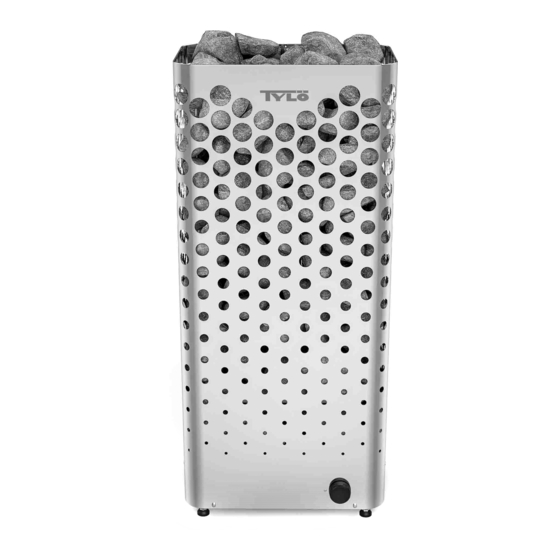
Summary of Contents for Tylo Air 10
- Page 1 TYLÖ AIR 1604 SVENSKA РУССКИЙ INSTALLATIONSANVISNING ИНСТРУКЦИИ ПО УСТАНОВКЕ ENGLISH POLSKI INSTALLATION GUIDE INSTRUKCJA INSTALACJI DEUTSCH NEDERLANDS INSTALLATIONSANLEITUNG INSTALLATIEHANDLEIDING FRANÇAIS NOTICE D’INSTALLATION 2900 5230...
- Page 2 PRIOR TO INSTALLATION • The heater's output (kW) must be adapted to the sauna's volume (m³) (see Table 1). The minimum and maximum Parts volumes must not be exceeded. Check that the following parts are included in the packaging: NOTE! A brick wall without heat insulation increases the warm-up time.
- Page 3 If the wall on which the sensor is to be installed is made of highly heat-absorbing material (e.g. concrete, brick, etc.), or of hardened glass, the sensor may be installed in the ceiling at a distance from the heater, according to Figure 4. Figure 2: Schematic diagram of installation Sauna heater Control panel...
- Page 4 Positioning the air intake vent Position the air intake vent straight through the wall behind the center line of the heater (see Figure 6). Vent size for a family sauna approx. 125 cm². The air circulation from the door must work together with the hot air circulation from the heater.
- Page 5 Connect the sensor cable (6) to the NTC contact on the circuit board (position 1) (5) (see the Connection/wiring diagram section) according to the wiring diagram (see the Connection/wiring diagram section, page 11). Connect the light cable (if relevant) (7), see Figure 8 page 9, to the terminal (8) according to the wiring diagram Figure 11, page 11.
- Page 6 CONNECTION/WIRING DIAGRAM 400-415 V 3N~/3~ 230-240 V 3~ 230-240 V~ Output kW Amperage Wiring area Amperage Wiring area Amperage Wiring area mm² mm² mm² 10.5 * 10.5kW is not approved for 230V~ in Europe. RJ10 4P4C 2 x 1.5 mm RJ10 4P4C RJ10 4P4C RJ10 4P4C...
- Page 7 Description of cabling/modular contacts Pin: Pin: Figure 12: Modular contacts, description 1. NTC Sensor 2. Ext switch 3. Door switch 4. SEC/NTC Sensor (option) 5. RS485 control panels 6. RS485 control panels 7. RS485 control panels 8. RS485 control panels 9.


Need help?
Do you have a question about the Air 10 and is the answer not in the manual?
Questions and answers