
Related Manuals for Ocean Optics OCEAN FX-UV-VIS


Summary of Contents for Ocean Optics OCEAN FX-UV-VIS
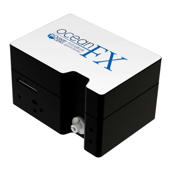
- Page 1 Ocean FX Miniature Spectrometer User Manual Amy to r For Product: OCEAN FX Document: 226-00000-000-01 Version: 1.3...
- Page 3 Every effort has been made to make this manual as complete and as accurate as possible, but no warranty or fitness is implied. The information provided is on an “as is” basis. Ocean Optics, Inc. shall have neither liability nor responsibility to any person or entity with respect to any loss or damages arising from the information contained in this manual.
-
Page 4: Table Of Contents
Table of Contents Compliance ........................vi Warnings & Cautions ..................... viii About This Manual ......................ix Document Summary ........................ix Product-Related Support and Documentation ................x Warranty ........................xi Chapter 1 .................... 1 Introduction ..................1 Product Introduction ....................... 1 Product Features ........................ - Page 5 About This Manual Common UV-Vis Reflectance Applications ................31 Common UV-Vis Transmission Applications ................31 Fluorescence..........................32 Common Fluorescence Applications ..................32 Irradiance ........................... 33 Chapter 4 .................... 35 Ocean FX Operation with OceanView ..........35 Overview ........................35 Launch OceanView ......................35 OceanView Main Screen ....................
- Page 6 About This Manual Overview ........................56 Wavelength Calibration ....................56 About Wavelength Calibration ....................56 Calibrating the Spectrometer Wavelength ................. 57 Preparing for Calibration ......................57 Calibrating the Wavelength of the Spectrometer ............... 57 Irradiance Calibrations ....................59 226-00000-000-01...
- Page 7 About This Manual Tables Table 1 ............................ix Table 2 ............................2 Table 3 ............................4 Table 4 ............................5 Table 5 ............................5 Table 6 ............................7 Table 7 ............................8 Table 8 ............................12 Table 9 ............................27 Table 10 ............................
-
Page 8: Compliance
About This Manual Compliance WARNING This is a FCC Class A product. In a domestic environment, this product may cause radio interference in which case the user may be required to take adequate measures. FCC COMPLIANCE This equipment has been tested and found to comply with the limits for a Class A digital device, pursuant to Part 15 of the FCC Rules. - Page 9 EN 61326-1:2013 CISPR 11:2009.A1:2010 CAN ICES-003, issue 6 EMC 2004/108/EC RoHS-compliant ISO COMPLIANCE Ocean Optics, the industry leader in miniature photonics, has been certified for ISO 9001:2008 certification applicable to the design and manufacture of electro-optical equipment since 2009. 226-00000-000-01...
-
Page 10: Warnings & Cautions
USB connector. Caution: The user of this spectrometer shall have the sole responsibility for any malfunction which results from improper use, faulty maintenance, improper repair, damage or alteration by anyone other than Ocean Optics or their authorized service personnel. 226-00000-000-01 viii... -
Page 11: About This Manual
About This Manual About This Manual Document Summary Chapter Description Chapter 1: Introduction Introduces the product features. Contains descriptive information about the Ocean FX Spectrometer. It also provides a list of system requirements, typical applications, and product versions. Chapter 2: How the Ocean FX Describes how the Ocean FX operates, illustrating the various Spectrometer Works... -
Page 12: Product-Related Support And Documentation
Thermoelectric Cooling Product-Related Support and Documentation You can access product documentation for Ocean Optics products by visiting our website at http://www.oceanoptics.com. Go to the Ocean FX product page for general product details, specifications and application notes. Additional technical documents and programs can be... -
Page 13: Warranty
Ocean Optics’ liability is limited to the repair or the replacement, at our option, of any defective item and shall not include incidental or consequential damages whatsoever. Ocean Optics reserves the right to replace a discontinued model with a functionally comparable model. -
Page 15: Chapter 1
The Ocean FX is a miniature modular spectrometer with enhanced connectivity and onboard processing that is based upon Ocean Optics’ Cross Czerny-Turner design. Ocean FX is built using manufacturing techniques that help deliver high thermal stability and low unit to unit variation without compromising the flexibility and configurability that are the hallmark of the design. -
Page 16: Product Features
1: Introduction Product Features Fast Acquisition Speed Integration times down to 10µs, acquire and process more spectral data in less time for faster, more reliable answers Sensitive Responsive from 190 – 1100 nm with great sensitivity in the UV and NIR Multiple Configurations Incredibly configurable, with millions of configurations across the wavelength range 190-1100nm... -
Page 17: Typical Applications
1: Introduction Typical Applications Application Area Examples Laser Characterization Light Laser LED LED Measurement Light Metrology Measurement Applied Research Research and Education Basic Research Teaching Labs for Physics, Chemistry, Biomed Biotechnology Life Sciences Medical Diagnostics Protein and Nucleic Acid Analysis Biomaterial Analysis Materials Identification Metallurgical Analysis... -
Page 18: Table
1: Introduction Application Area Examples Biofuels Analysis Energy Technologies Mining and Exploration Oil and Petroleum Analysis Photovoltaic Analysis Solar Simulators Testing and Qualification Anti-Counterfeit Product Identification and Authentication Defect Identification Quality Control and Process Monitoring Raw Material Inspection Verification Testing Air and Water Quality Analysis Environmental Monitoring Remote Sensing... -
Page 19: Product Versions
Table 4 Product Versions Many variants of the Ocean FX Spectrometer exist. Ocean Optics offers both preconfigured units as well as custom-configured units, enabling you to order a customized spectrometer optimized for your application. You can determine spectrometer details by looking at the product code located on the bottom of your spectrometer. -
Page 20: Chapter 2
Chapter 2 How the Ocean FX Spectrometer Works Overview This section provides an overview of the Ocean FX spectrometer and how it works from light entering the slit to the communication of the spectrum to a connected device. It also provides an overview of all the different possible configurations that are possible, designed to help you optimize your spectrometer for specific applications. -
Page 21: Table
50µm; 100µm and 200µm Table 6 Ocean Optics also offers a range of FC connector slits in the same wavelengths, with the product code INTFC-XXX. An INTFC-KIT is also available. Note that these items are made to order and have a longer lead time. Contact an Ocean Optics Application Sales Engineer for more details. -
Page 22: Table
2: How the Ocean FX Spectrometer Works 3. Absorbing Filter (optional): If selected, an absorbing filter is installed between the slit and the aperture in the SMA 905 bulkhead. The filter is used to limit bandwidth of light entering spectrometer or to balance color. Filters are installed permanently. A filter is for a specific slit. - Page 23 2: How the Ocean FX Spectrometer Works Reflectance vs. Wavelength for Aluminum, Gold, and Silver Mirrors By Bob Mellish in Wikipedia 5. Grating: In optics, a diffraction grating is an optical component with a periodic structure that splits and diffracts light into several beams traveling in different directions. The directions of these beams depend on the spacing of the grating and (most importantly for spectroscopy) the wavelength of the light.
- Page 24 2: How the Ocean FX Spectrometer Works 6. Focusing Mirror (specify standard or SAG+): This mirror focuses first-order spectra on the detector plane. Both the collimating and focusing mirrors are made in-house to guarantee the highest reflectance and the lowest stray light possible. You can opt to install a standard or SAG+ mirror.
-
Page 25: Chapter 3
Cable to connect your spectrometer to your network switch. The supplied cable supports Gigabit speed. Getting Started Reference Card The Ocean Optics Getting Started reference will guide you in ways that you can find further information to configure and use your spectrometer and software. Wavelength Calibration Data Sheet ... -
Page 26: Ocean Fx Installation
3: Installation and Setup Ocean FX Installation The following procedure provides general instructions for getting your new Ocean FX spectrometer up and running. Software Installation Caution Be sure to install the software BEFORE connecting the spectrometer to your PC. The software installs the drivers required for spectrometer installation. If you do not install the software first, the system will not properly recognize the spectrometer. -
Page 27: About Oceanview
3: Installation and Setup About OceanView OceanView is a spectroscopy software platform that operates on Windows, Macintosh and Linux operating systems. The software can communicate with Ocean FX devices through USB, Ethernet or WiFi. OceanView is a user-customizable, advanced acquisition and display program that provides a real-time interface to a variety of signal-processing functions. -
Page 28: Configuration For Usb Or Ethernet Connection
3: Installation and Setup Configuration for USB or Ethernet Connection Important Note To ensure reliable operation, it is recommended that the power supply be connected prior to inserting the USB or Ethernet connector. Important Note For Ethernet to connect properly, the host computer must be wirelessly connected to the same router as the Ethernet cable or the Wireless functionality within the host computer must be turned OFF. - Page 29 3: Installation and Setup 6. Click on the device manager icon. 7. Verify that: a. “Automatically connect to device” is checked. b. “Simulate device if none found” and “Automatically connect to remote device” are not checked as shown below. Click the Exit button. 8.
- Page 30 3: Installation and Setup 9. Select the OceanView’s “Schematic” view if not already the active view. This can be done by clicking Schematic Window on the side bar or by choosing Schematic from the Window tab. 10. The Ocean FX icon will show up in OceanView’s schematic window as shown below. 226-00000-000-01...
- Page 31 3: Installation and Setup 11. If the device does not appear, go back to Device Manager and click the “Rescan” button. Your Ocean FX device will appear in the Device Manager window and in the schematic view. 13. If the icon is out of focus it indicates that a device is present, but not connected. 226-00000-000-01...
- Page 32 3: Installation and Setup This can be verified by noting that the “In Use” checkbox does not have a check mark. Click the “Connect” button. If the “In Use” checkbox is checked already, click the “disconnect” button and then click the “Connect” button. The check mark will appear in the box and the icon will no longer be out of focus.
-
Page 33: Configuration For Wifi Connection
3: Installation and Setup Configuration for WiFi Connection Important Note Initial configuration must be done via USB prior to attempting a WiFi connection. Important Note The host device with OceanView must be connected to the WiFi router. Important Note Before attempting WiFi configuration, the Ocean FX must be powered on for at least 2 minutes. - Page 34 3: Installation and Setup 2. Select Interface 1. If necessary, click the “Interface Enable” button. If the WiFi settings do not appear under Interface 1, then close the window and right click again on the Ocean FX icon and select “Network Setup”. WiFi options will appear under Interface 1. 3.
- Page 35 3: Installation and Setup 4. Then select Wireless Network under Interface 1. Mode will default to Client. Enter the SSID for the network device and click the “Apply” button. 5. Select Address. Verify the “Enable DHCP” box is checked. If not, check the box. 226-00000-000-01...
- Page 36 3: Installation and Setup 6. Select Multicast. If necessary, click the “Enable Multicast (discovery)” button. Finally, select Interface 1 and then click the “Save as Defaults” button which will save the SSID and passphrase. 7. Wait 1 minute and verify that the Ocean FX is within 15 feet of the WiFi router. 8.
- Page 37 3: Installation and Setup 9. Verify the USB device is highlighted. Click on the “Disconnect” button for the USB device. 10. Both devices should now indicate that they are not in use. 11. Highlight the WiFi connected device and click the “Connect” button. 226-00000-000-01...
- Page 38 3: Installation and Setup 12. At this point you may disconnect the Ocean FX from the configuring USB cable. Only the WiFi connection will be displayed in Device Manager. Check the “Automatically connect to remote devices” checkbox before exiting. This will allow OceanView to wirelessly connect to the Ocean FX when OceanView is opened.
-
Page 39: Power Sequences
3: Installation and Setup Power Sequences Power ON Sequence Power up the Ocean FX prior to opening controlling software such as OceanView. Before starting software, the following wait times are needed for proper connectivity operation: USB: No wait time Ethernet: Wait 1 minute WiFi: Wait 2 minutes... -
Page 40: Experiment Setup
1. Connect any spectroscopy accessories. To find operating instructions for Ocean FX- compatible products (such as light sources, sampling chambers, and probes) go to the Technical Documents section of the Ocean Optics website under the Support menu. 2. Attach the fiber to the fiber optic connector on the spectrometer. -
Page 41: Ocean Fx Indicator Lights
3: Installation and Setup Ocean FX Indicator Lights The Ocean FX features two indicator lights that operate as shown below: Light Steady Flashing Power is on, Unit is acquiring data unit is booting or in idle state green Heartbeat Table 9 Indicator lights can be turned off in OceanView or by using a firmware command. - Page 42 3: Installation and Setup Important Note When changing the slit, there is no need to perform a wavelength calibration on the spectrometer. Just install and start measuring. Procedure ► 1. Find the SMA connector. If a fiber or protective cap is attached, remove it. Slit 2.
-
Page 43: Accessories
3: Installation and Setup Accessories Ocean Optics provides a range of standard cables and accessories that connect the Ocean FX to our large range of sampling and light source accessories utilizing the DD4 connector on the front of the Ocean FX spectrometer. Items specifically designed for the Ocean FX are described here;... -
Page 44: Measurement Techniques - Typical Set-Ups
3: Installation and Setup Measurement Techniques – Typical Set-ups The Ocean FX, in conjunction with Ocean Optics light sources and sampling accessories, can be used for many different measurement techniques. One of the key advantages of modular fiber optic spectroscopy is that you can change components of the system without having to buy a whole new system. -
Page 45: Reflectance & Transmission
3: Installation and Setup Reflectance & Transmission Reflectance spectroscopy compares the relative level of light reflected off a sample compared with a reference (given as a percentage of the reference spectrum at each wavelength). A reflectance standard is used to set the reference level of 100%. -
Page 46: Fluorescence
3: Installation and Setup Fluorescence Fluorescence is a technique where a sample is excited with a light source and fluorescent light emitted from the sample at a higher wavelength is measured by the spectrometer. Typically the excitation source is applied at 90º to the sample to minimize light from the excitation source reaching the spectrometer. -
Page 47: Irradiance
3: Installation and Setup Irradiance Irradiance is the technique of measuring the total energy of light at a given wavelength, either relative to the spectral output of a known source (relative irradiance) or in absolute units of power or energy (absolute irradiance). - Page 48 3: Installation and Setup Typical Set-up for an Absolute Irradiance Measurement Using Field Calibration with a Calibrated Light Source Common Irradiance Applications Measuring the radiant output of lamps and LEDs Measuring color using relative irradiance Measuring the color rendering index (CRI) ...
-
Page 49: Chapter 4
Chapter 4 Ocean FX Operation with OceanView Overview The following information enables you to perform the basics of acquiring and saving data with your Ocean FX Spectrometer and OceanView software. More detailed information about OceanView is in the OceanView Manual. Launch OceanView Once you have installed your software and connected your spectrometer, start OceanView which will display the Welcome Screen. -
Page 50: Oceanview Main Screen
4: Operation OceanView Main Screen No matter what route you take on start up, you will soon end up on the OceanView main screen. This is where you can set and view acquisitions, save data, load data and save projects. 1. -
Page 51: Connect The Ocean Fx In Oceanview
4: Operation Connect the Ocean FX in OceanView Initial Configuration Refer to the section for the initial steps for your new Ocean FX spectrometer. Once the initial configuration is done, follow the steps below for when you connect your device. The Ocean FX should automatically appear when you start OceanView and should be acquiring with the default acquisition parameters. -
Page 52: Set Acquisition Parameters
4: Operation Set Acquisition Parameters Set Acquisition parameters in the Acquisition Group Window to control the spectrometer. This window may be minimized when you first start OceanView. You can either expand or open a new window from the menu (Window | Acquisition Group). An active acquisition is required for the Acquisition window to appear. -
Page 53: Save Data
4: Operation Save Data Configure Saving, set saving parameters and file type, file directory and file naming convention. Once selected, the file directory will persist until changed. Start saving data. Turns red when save is active. If saving data continuously, click when red to stop saving. -
Page 54: Projects And Methods
4: Operation 1. Saved Files List of saved files currently in the saved directory arranged by name or date. 2. Preview Shows a preview of the saved spectra, time series or appended series saved data can be stepped through acquisition by acquisition using the controls above the saved files list. -
Page 55: Dark And Reference Measurements
4: Operation Dark and Reference Measurements Dark and reference measurements are commonly used in spectroscopy. Dark Measurements – subtract a background signal from the spectrum. This can be considered the removal of a constant error. Typically this is done when the light source is off to remove any background from the ambient environment, hence the name dark. - Page 56 4: Operation The schematic view is a graphical interface that allows you to move from device through to processed data. There are a few basic components to consider. Devices – Each spectrometer will appear as a separate device. Right click to open a menu that can generate an acquisition, control a TEC (if applicable) and add other device controls.
-
Page 57: Chapter 5
Sometimes things do not go to plan. If not, do not hesitate to contact us and our Tech Support team will leap into action. Some typical questions are answered here. For more information, consult the FAQs on the Ocean Optics website. Frequently Asked Questions How do I know my spectrometer has power? The red LED on the spectrometer should be on steadily if the unit is receiving power. - Page 58 If your spectrometer is not recognized by OceanView on your computer, you need to manually install the spectrometer drivers. See your OceanView manual for this procedure. Also consult the Correcting Device Driver Issues document on the Ocean Optics website. 226-00000-000-01...
-
Page 59: Microsoft Windows Operating Systems
Microsoft Windows Operating Systems Important Note If these procedures do not correct your device driver problem, you must obtain the Correcting Device Driver Issues document from the Ocean Optics website. Remove the Unknown Device from Windows Device Manager Procedure ►... - Page 60 5: Troubleshooting I have both SpectraSuite and OceanView installed. Will my spectrometer work with both? Ocean FX only works with OceanView 1.6 and later. I’m attempting to connect via Ethernet but I cannot see the spectrometer. What do I do? Connect the spectrometer to the computer utilizing the USB cable.
- Page 61 5: Troubleshooting Product Upgrades, Repairs and Servicing Occasionally, you may find that you need Ocean Optics to make a change or an upgrade to your system. To facilitate these changes, you must first contact Customer Support and obtain a Return Merchandise Authorization (RMA) number. Please contact Ocean Optics for specific instructions when returning a product.
-
Page 62: Chapter 6
Chapter 6 Technical Specifications Mechanical Diagram Ocean FX Outer Dimensions 226-00000-000-01... -
Page 63: Absolute Maximum Ratings
6: Technical Specifications Absolute Maximum Ratings Input Voltage (Vin, VBatt, GPIO) 0 to +5.5V Input Voltage (RS232) +/- 25V Input Voltage (I2C, SPI, Other I/O) 0 to +3.6V Table 10 Performance Specifications Storage Temperature -30°C to +70°C Storage Humidity 0 to 90% RH non-condensing Operating Temperature 0°C to +50°C Operating Humidity... -
Page 64: Table 12
6: Technical Specifications Electrical Characteristics PARAMETER CONDITIONS TYP MAX UNITS Input Current +5.0V, external power supply (Note Supply Voltage (Vin) 4.75 5.25 GPIO Logic Input Low GPIO Logic Input High GPIO I SOURCE SINK GPIO Output Low = 1 mA SOURCE GPIO Output High = 1 mA... -
Page 65: Table 13
6: Technical Specifications Optical and Spectroscopic Characteristics PARAMETER UNITS Detector Response Range 1100 (note 2) Integration Time 10E6 µs Single Scan Dynamic Range 6423 System Dynamic Range 7.3E7 (Note 3) Single Scan Signal-to-Noise Resolution (FWHM) 2.39 (Note 4) Stray Light a.u. -
Page 66: Accessory Connectors
6: Technical Specifications Accessory Connectors DD4 Accessory Connector The Ocean FX features a 40-pin Accessory Connector, located on the front of the unit as shown: connector Location of Accessory Connector The Ocean FX features a 40-pin Accessory Connector (Part Number: DD4RA40JA1) that has two mating connectors available: DD4PA40MA1 (right angle) and DD4BA40WA1 (vertical). -
Page 67: Table 15
6: Technical Specifications PIN# SIGNAL NAME VOLTAGE DESCRIPTION LEVEL GPIO_0 +3.3/+5.0 General Purpose Software Programmable Digital Inputs/Output, Analog Output. Digital Outputs are GPIO_1 3.3V. Analog Outputs Can Be Programmed To 2.5V GPIO_2 or 5.0V Max. GPIO_3 GPIO_4 GPIO_5 GPIO_6 GPIO_7 System Ground SPI_SCLK +3.3... -
Page 68: I2C
I2C data without direction from the host system. The I2C lines are pulled up internally. DB15 Connector Cable (OCEAN FX-CBL-DD4P-DB15P) This cable connects the Ocean FX to existing Ocean Optics accessories that use a DB-15HD connector. These include the PX-2, LLS and HL-2000-FHSA light sources. DD4 to DB15 Pin Connections... -
Page 69: Table 16
6: Technical Specifications GPIO 2 Ground I2C SDA I2C SCL Lamp Enable Reserved (NC) GPIO 4 Table 16 226-00000-000-01... -
Page 70: Chapter 7
This section describes how to calibrate the wavelength of your spectrometer. Though each spectrometer is calibrated before it leaves Ocean Optics, the wavelength for all spectrometers will drift slightly as a function of time and environmental conditions. See the Technical Specifications for recommended calibration frequency. -
Page 71: Calibrating The Spectrometer Wavelength
A light source capable of producing spectral lines Important Note Ocean Optics’ HG-1 Mercury-Argon lamp is ideal for recalibration. If you do not have an HG-1, you need a light source that produces several (at least 4-6) spectral lines in the wavelength region of your spectrometer. - Page 72 7: Calibration Independent Values Computed Dependent from the Regression Variable Variables Output Predicted True Wavelength (nm) Pixel # Pixel # Pixel # Difference Wavelength 253.65 30625 5359375 253.56 0.09 296.73 87616 25934336 296.72 0.01 302.15 97344 30371328 302.40 -0.25 313.16 116964 40001688 313.02...
-
Page 73: Irradiance Calibrations
Keep these values at hand. Saving the New Calibration Coefficients: OceanView Ocean Optics programs wavelength calibration coefficients unique to each Ocean FX onto an EEPROM memory chip in the Ocean FX. You can overwrite old calibration coefficients on the EEPROM if you are communicating with the Ocean FX via OceanView.
Need help?
Do you have a question about the OCEAN FX-UV-VIS and is the answer not in the manual?
Questions and answers