Table of Contents

Subscribe to Our Youtube Channel
Related Manuals for Merrychef eikon e4s


Summary of Contents for Merrychef eikon e4s
- Page 1 eikon ® Service & Parts Manual ® WARNING MICROWAVE EMISSIONS DO NOT BECOME EXPOSED TO EMISSIONS FROM THE MICROWAVE GENERATOR OR PARTS CONDUCTING MICROWAVE ENERGY. Service & Parts Manual original instructions Part Number 32Z3870 GB Issue 4...
- Page 2 SYMBOLS The symbols below are used, where applicable, as visual guidance throughout this manual. The relevant safety precautions MUST be observed and implemented at all times. DANGER! This symbol is shown if there is a immediate risk of severe personal physical injury or death. WARNING This symbol is shown if there is a possible risk of severe personal physical injury.
-
Page 3: Table Of Contents
CONTENTS SAFETY & REGULATIONS 15.1 High Voltage Transformer Test 15.2 High Voltage Rectifier Test (Diode Board) 1 SAFETY REQUIREMENTS 15.3 High Voltage Capacitor Test PRODUCT DETAILS 15.4 High Voltage Magnetron Test 2 PRODUCT OVERVIEW & FUNCTIONS 16 MAINS VOLTAGE COMPONENTS 3 MAIN FEATURES 16.1 Door Interlock Adjustment 4 TECHNICAL SPECIFICATIONS... -
Page 4: Safety Requirements
ISOLATE FROM THE ELECTRICAL SUPPLY - KEEP THE OVEN DOOR CLOSED TO STIFLE ANY familiarisation and training course run by Merrychef to carry FLAMES. out service/repair tasks to the appliance/s shown on the front cover of this manual which must not be used for any other make or model of appliance. -
Page 5: Product Overview & Functions
2 PRODUCT OVERVIEW & FUNCTIONS CONSTRUCTION Stainless Steel cavity and casework. CONTROL SYSTEM Colour touchscreen, icon driven. Storage for up to 1024 programs with 6 stages per cooking program providing a user instruction for each stage. USB memory stick data transfer. Safety system: ensures control area temperature is within limits. -
Page 6: Main Features
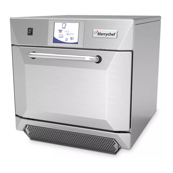
3 MAIN FEATURES 1 ON/OFF SWITCH ON (I) activates the oven, OFF (0) switches the oven to standby mode. IT DOES NOT ISOLATE INTERNAL WIRING FROM THE MAINS SUPPLY. 2 CONTROL PANEL Touch sensitive controls (easyToUCH®) for controlling oven functions, including diagnostics and service mode. -
Page 7: Technical Specifications
4 TECHNICAL SPECIFICATIONS 4.1 Specifications Description unit Touch screen controls programs 1024 Ambient operating temperature °C/°F <40/104 External HxWxD 591x584x750 External HxWxD inches 23.3x23.0x29.5 Internal HxWxD 218x375x361 Internal HxWxD inches 8.6x14.8x14.2 Cooking chamber Ltr (cu.ins) 29.5 (1800) Power output microwave Watts 1800 Power output convection... - Page 8 Nether Lane, Ecclesfield, Sheffield, S35 9ZX Equipment details Generic Model Numbers eikon e4s Description Commercial Combination Microwave Oven Declaration of Conformity with directives and standards The manufacturer hereby declares that its commercial combination microwave ovens listed above comply with the following directives and standards.
-
Page 9: Installation
5 INSTALLATION OVEN LOCATION AND POSITIONING Choose a site away from major heat sources. DO NOT position so that hot air is drawn in from fryers, grills, griddles, etc. A heat barrier to the height of the oven must be installed if sited next to a burner, stove or range. -
Page 10: Electrical Installation
6 ELECTRICAL INSTALLATION DANGER! THIS APPLIANCE MUST BE EARTHED. FAILURE TO DO SO MAY RESULT IN ELECTRIC SHOCK AND DEATH. The oven must be connected to a separate electrical supply installed by a qualified and approved electrician. A suitably rated isolating switch with a 3mm contact gap on all poles should be fitted for each oven installed. -
Page 11: Electrical Installation Guide
7 ELECTRICAL INSTALLATION GUIDE DANGER! WARNING THIS APPLIANCE MUST BE EARTHED. HIGH LEAKAGE CURRENT FAILURE TO DO SO MAY RESULT IN ELECTRIC SHOCK AND DEATH. The oven must be connected to a separate EQUIPOTENTIAL electrical supply installed by a qualified and An Equipotential Earth point is provided on approved electrician. -
Page 12: Oven Control Settings
8 OVEN CONTROL SETTINGS 1. Select the ‘settings’ symbol from the main menu screen. 2. Enter the password and select OK to display the Settings menu (3) comprising: A. Oven mode/navigation settings. B. Language options. C. Oven temperature settings and labels. D. -
Page 13: Recipe Counters (E)
8.4 Recipe counters (E) 8.4.1 Select the clipboard symbol to display a listing of recipe counters. 8.4.2 If shown, use the arrows (bottom right) to scroll up and down the list. 8.5 Date and Time settings (F) 8.5.1 Select the time/date symbol to display the setting options. -
Page 14: Usb Oven Programs (J)
Check that the key has the correct number/code for the programs you want to load into the oven memory (1 ‘.cbr’ + ‘autoupd.ate’). 8.8.1 With the oven switched off, slide the Merrychef badge (oven front top right) upwards and insert the USB Memory Stick into the slot. -
Page 15: Cooling The Oven Down Before Cleaning
Equipment required (not supplied) ● Merrychef® approved oven cleaner ● Merrychef® approved oven protector (optional) ● Heat proof gloves ● Protective rubber gloves ● Non–abrasive nylon scrub pad ●... -
Page 16: Cold Oven Cleaning Instructions
DO NOT USE THE OVEN WITHOUT A CLEAN AIR FILTER IN PLACE. APPLY OVEN PROTECTOR 1. Only apply to a clean oven. Spray a Merrychef® approved oven protector onto a sponge. 2. Spread oven protector lightly onto all internal surfaces of the oven avoiding cooking surfaces, fan inlets and outlets. -
Page 17: Servicing The Oven
11 SERVICING THE OVEN 11.1 Servicing Procedure DANGER! 11.1.1 Disconnect/isolate the oven from the power BEFORE REMOVING THE OVEN CASING, ISOLATE THE supply. OVEN FROM THE MAINS ELECTRICITY POWER SUPPLY; SWITCH OFF, DISCONNECT OVEN PLUG FROM WALL 11.1.2 Check the oven is correctly installed as SOCKET, TURN OFF ISOLATOR SWITCH TO DISCONNECT described in the Installation Instructions (“Product FIXED WIRED OVENS AND LOCK-OFF. -
Page 18: Errors & Diagnostics
12 ERRORS & DIAGNOSTICS 12.1 ERROR MESSAGES 12.1.1 A description of the type of error is shown. Check for a number following ‘ERROR:’ (A) and refer to the Error Codes (“Fault Finding” section) for more details. The Oven Serial Number, Model, UI (QTS) version and SRB version information is also displayed below. -
Page 19: Visual View
12.5 VISUAL VIEW 12.5.1 Select VISUAL VIEW (E) to check the main oven components. Select a component symbol to switch on (red), select again to increase the level or turn off (green). 12.5.2 Remove the front air intake filter, the colour should change from green to red on the display indicating that the magnetic reed switch circuit for the air intake filter is operating. -
Page 20: Firmware Updates
13 FIRMWARE UPDATES NOTE: If icons are not displayed on the screen, press in the same positions on screen as the missing icons to select. 13.5.1 Switch on the oven. 13.5.2 Tap the top right of the screen (1) or the same position if it is not displayed to bypass oven preheat. - Page 21 13.5.9 Enter the password and select OK to display the Settings menu, see (2). 13.5.10 Select the USB symbol (4). 13.5.11 Slide the Merrychef badge (oven front top right) upwards and insert the USB Memory Stick into the slot (3).
- Page 22 For update A) follow all instructions: For update B) follow the first 2 instructions: 13.5.24 With the oven switched off, slide the Merrychef badge (oven front top right) upwards and insert the USB Memory Stick into the slot (1). 13.5.25 Switch the oven ON (2).
-
Page 23: Oven Testing
14 OVEN TESTING 14.1 Equipment required DANGER! ● Portable Appliance Tester (P.A.T.). BEFORE REMOVING THE OVEN CASING, ISOLATE THE OVEN FROM THE MAINS ELECTRICITY POWER SUPPLY; ● Digital Multi-meter (D.M.M.). SWITCH OFF, DISCONNECT OVEN PLUG FROM WALL ● Megger / similar 500V d.c. resistance meter. SOCKET, TURN OFF ISOLATOR SWITCH TO DISCONNECT ●... -
Page 24: Oven Tests
14.4 Oven Tests 14.4.1 Enter Service Mode (see “Servicing” section). 14.4.2 Select the down arrow to display the individual Oven tests (A) for the oven to perform. 14.5 Microwave Power Test Measuring the power output: NOTE: The power output is established under IEC 705 standard method which is only workable in laboratory controlled conditions. -
Page 25: Microwave Leakage Test
14.6.8 Readings must be below 5mW/cm². If a level greater than 5mW/cm² is observed, this should be reported to the Merrychef Service Department immediately, and the oven should not be used. 14.6.9 Notes should be kept of any leakage that is observed in terms of the level and position on the oven. -
Page 26: Temperature Control Test
14.7 Temperature Control Test Measuring the oven cavity temperature. NOTE: Re-calibrating the Thermocouple with the SRB is normally only required when the Thermocouple has been replaced or the oven is under or over cooking. Procedure: 14.7.1 Place the probe of a temperature reader (A) onto a heat sink or a metal plate in the centre of the oven cavity and close the oven door. -
Page 27: Soak Test
14.8 Soak Test Checking the oven cavity integrity. Procedure: 14.8.1 Place an oven/microwave safe container with approx. 2 litres of water into the oven. 14.8.2 Close the oven door and select ‘Soak Test’ (A) from the Service mode oven tests (maximum oven temperature, 50% microwave power, maximum fan speed). -
Page 28: High Voltage Components
15 HIGH VOLTAGE COMPONENTS High voltages and large currents are present at DANGER! the High Voltage Capacitor. It is very dangerous BEFORE REMOVING THE OVEN CASING, ISOLATE THE to work near this part when the oven is on. OVEN FROM THE MAINS ELECTRICITY POWER SUPPLY; NEVER make any voltage measurements at the SWITCH OFF, DISCONNECT OVEN PLUG FROM WALL High Voltage circuits, including the magnetron... -
Page 29: High Voltage Capacitor Test
High voltages and large currents are present at the High Voltage Capacitor. It is very dangerous to work near this part when the oven is on. NEVER make any voltage measurements at the High Voltage circuits, including the magnetron filament. 15.3 High Voltage Capacitor Test 15.3.1 Disconnect and isolate the oven from the electricity supply. -
Page 30: Mains Voltage Components
16 MAINS VOLTAGE COMPONENTS 16.1 Door Interlock Adjustment Located on the door hinges are 3 safety interlock microswitches, to prevent microwave emissions escaping when the oven door is opened: The Primary (SW3) breaks the electrical supply circuit to the transformers. The Secondary (SW2) breaks the microwave circuit if the primary fails. -
Page 31: Convection Fan Motor & Controller
16.2 Convection Fan Motor & Controller 16.2.1 Convection Fan Motor. The convection motor Is a 3-phase AC motor having a maximum speed of 7200 rpm controlled by a motor speed controller. The windings are thermally protected and in the event of a thermal fault a trip inside the motor will operate and shut down the motor speed controller. -
Page 32: Oven Components
17 OVEN COMPONENTS DANGER! BEFORE REMOVING THE OVEN CASING, ISOLATE THE OVEN FROM THE MAINS ELECTRICITY POWER SUPPLY; SWITCH OFF, DISCONNECT OVEN PLUG FROM WALL SOCKET, TURN OFF ISOLATOR SWITCH TO DISCONNECT FIXED WIRED OVENS AND LOCK-OFF. WARNING ALLOW OVEN TO COOL. OBSERVE AND FOLLOW ALL SAFETY PRECAUTIONS INCLUDING THOSE DESCRIBED UNDER THE “SAFETY REGULATIONS”... - Page 33 51 Magnetron cooling duct RH 11 Magnetron 33 Heater element x2 (connectors shown) 65 Motor assembly convection fan 24 Gland Power supply cable 52 Magnetron cooling duct LH 62 HT Diode 85 Transformer 69 Cooling fan motor Capacitor 1.5µF (Silver) motor start 13 Overheat stat Magnetron 17 QTS Touch Screen PCB Switch oven ON/OFF (rear connection)
-
Page 34: 18 Srb & Qts Circuit Boards
18 SRB & QTS Circuit Boards 18.1 SRB replacement 18.1.1 Disconnect and isolate the oven from the electricity supply. 18.1.2 Allow the oven to cool down. 18.1.3 Remove the oven casing. 18.1.4 Ensure that the High Voltage Capacitor is discharged before commencing work. 18.1.5 Taking anti-static precautions, disconnect all connections on the SRB. -
Page 35: Pm (Personality Module) Replacement
18.3.3 Enter the service password and select OK to display the Settings menu, see (3). 18.3.4 Select the USB symbol (4). 18.3.5 Slide the Merrychef badge upwards and insert the USB Memory Stick into the slot (5). 18.3.6 Once the USB has stopped flashing, select the required USB recipe symbol (6). -
Page 36: Spare Parts Exploded View
19 SPARE PARTS EXPLODED VIEW Service & Parts Manual original instructions Part Number 32Z3870 GB Issue 4... -
Page 37: Spare Parts
20 SPARE PARTS Parts list & recommended minimum stock holding & Service Kits Merrychef eikon e4s Oven Recommended Parts List Recommended Minimum Stock Holding & Service Kits Service Part 1-10 11-50 51-100 Unique Description Unit Aid/To Centre Number Ovens Ovens... - Page 38 SA3150 e4s LOWER CAT ASSY SA3151 e4s UPPER CAT ASSY SA3153 e4s AIR DIFFUSER ASSY eikon e4s 230Volts 50Hz - UK/EU - Single Phase - Unique Parts 30Z0231 FUSEHOLDER 1in (13A) 30Z0456 FUSE 1in 13A HRC 30Z1425 TRANSFORMER 240V 50/60Hz 30Z1431 1.2uF 2500V CAPACITOR...
- Page 39 1.00uF 2500V CAPACITOR 30Z1488 e4s MAINS FILTER P30Z1230 60HZ TRANS MULTI TAP POWER SUPPLY LEAD HE (EU) eikon e4s 208V & 240V 60Hz - USA - Unique Parts 30Z0285 FUSEHOLDER 1 1/4in (13A) 30Z1331 1.00uF 2500V CAPACITOR 30Z1439 OMRON RELAY 12V...
-
Page 40: Fault Finding
21 FAULT FINDING 21.1 Operations Communication 21.1.1 The oven has 2 main parts being the QTS assembly (Keyboard, Screen, Logic) and the SRB (Relay board to switch and monitor the required operation). 21.1.2 The QTS is the master of the oven and instructs the SRB what to do, in turn the SRB communicates information on the operation back to the QTS. -
Page 41: Error Code List
21.2 Error Code List Error Error System Error Condition Description Trigger Possible Causes Code Level Response The current measured by the Failure of Display error Detects a magnetron Magnetron failed current sensing component/s in message until E 101 is not working Critical to energise transformer... - Page 42 Error Error System Error Condition Description Trigger Possible Causes Code Level Response Firmware update The QTS has has been carried Display error SRB firmware version found that SRB version out to the QTS message until E 110 incompatible with the firmware Critical conflict and the SRB has...
-
Page 43: Error Code For Re-Commission Test Messages
21.3 Error Code for re-commission test messages 89 Cooling Test Fail 90 Convection Test Fail 91 Turntable Test Fail 92 Heater Test Fail 93 Magnetron Test Fail 94 Filter In Test Fail 95 Filter Out Test Fail 96 Door Closed Test Fail 97 Door Open Test Fail 98 Incomplete Cleaning 21.4 Normal Messages... -
Page 44: Srb & Qts Circuit Boards
22 SRB & QTS Circuit Boards 22.1 QTS LEDs ● Run - Pulsing 1 second flash, indicating that the board has booted up. ● Power - Lit to show that there is a power supply from the SRB. ● P-Bus - Irregular flashing, indicating data communication with SRB. -
Page 45: Srb Led's
22.3 SRB LED’s ● P-Bus - Irregular flashing, indicating data communication with QTS. ● Run - Pulsing 1 second flash, indicating that the board has booted up. ● 12v & 5v - Lit to show voltage outputs from inboard transformer. ●... -
Page 46: Srb Terminal Locations
22.4 SRB Terminal Locations: 1 X3 - Output for e4s Convection Fan Speed Controller. 2 X101 - Voltage Selection Relay coil feeds.(US Only) 3 X18b - Air intake Filter Reed Switch. 4 X18e - Right Magnetron Overheat Thermostat. 5 X18d - Left Magnetron Overheat Thermostat. 6 X18c - Cavity Overheat Thermostat. -
Page 47: Circuit Diagrams
23 CIRCUIT DIAGRAMS 3rd ANGLE PROJECTION Mains Input Motor Speed Controller Mains Filter Delta Star Primary Micro Switch Green Blue Note Switches Shown in Door Closed Position Fuse Rating Fuse 25 Amp 25 Amp Blue 25 Amp 25 Amp Brown Convection Fan 12 Amp... - Page 48 X102b wires 31, 45 & 21 - common Neutral points as long as the wires have not changed the order is not relevant. eikon e4s X20 wires 60, 61, 62 & 63 being reversed will not affect e4s Wiring Diagram 50/60Hz ...
-
Page 49: Convection Fan
3rd ANGLE PROJECTION Mains Filters Motor Speed Controller Primary Micro Switch Green Blue Note Switches Shown in Door Closed Position Fuse Rating Fuse 25 Amp 25 Amp Blue 25 Amp 25 Amp Brown Convection Fan 12 Amp 13 Amp Brown On/Off Switch 12 Amp... - Page 50 X102b wires 31, 45 & 21 - common Neutral points as long as the wires have not changed the order is not relevant. eikon e4s X20 wires 60, 61, 62 & 63 being reversed will not affect e4s Twin Phase Wiring Diagram ...
-
Page 51: Power Connections E4S
23.1 POWER CONNECTIONS e4s Product e4s Neutral Single Phase & Neutral Model Heater circuit Microwave 1800W Convection heater 3.2kW Microwave circuit Control circuit Live Heater circuit Microwave circuit Control circuit Product e4s Neutral Twin Phase & Neutral Model Microwave 1800W Heater circuit Convection heater 3.2kW Control circuit... -
Page 52: Control Circuit E4S
23.2 CONTROL CIRCUIT e4s Service & Parts Manual original instructions Part Number 32Z3870 GB Issue 4... -
Page 53: Heater Circuit E4S
23.3 HEATER CIRCUIT e4s Mains Input - L2 RFI Filter 20 Amp x2.1 x14.1 Safety Heater Relay Temperature Powered by Safety Supply Input for Thermocouple Relay Current x14.2 Sense Processor Controlled SRB Board x2.2 Heater Element RFI Filter Mains Input - L1 Service &... -
Page 54: Microwave Circuit E4S
23.4 MICROWAVE CIRCUIT e4s Mains Input - L2 RFI Filter 20 Amp RHS SW2 Normally Open Door Interlock Switches Shown in x.10 Door Open Position so the switches are not activated LHS SW3 Normally Open SRB Board Safety Relay Microwave Powered By Safety Supply Relay Current Sense To SRB E101 Sence... -
Page 55: Commissioning The Oven
24 Commissioning the oven 24.1 Initial installation 24.2 After Service 1 Unpack the Oven and check for damage. Complete the following checks after the Oven has been Serviced/Repaired/Tested before connecting to the 2 Check Oven Accessories. mains electricity power supply: 3 Check location will provide adequate Ventilation. - Page 56 Service & Parts Manual original instructions Part Number 32Z3870 GB Issue 4...
- Page 57 Correct disposal of this product (Waste Electrical & Electronic Equipment) Applicable in the European Union and other European countries with separate collection systems. This marking shown on the product or its literature indicates that it should not be disposed with other household wastes at the end of its working life.
Need help?
Do you have a question about the eikon e4s and is the answer not in the manual?
Questions and answers