Merrychef Mealstream 401 Service Manual
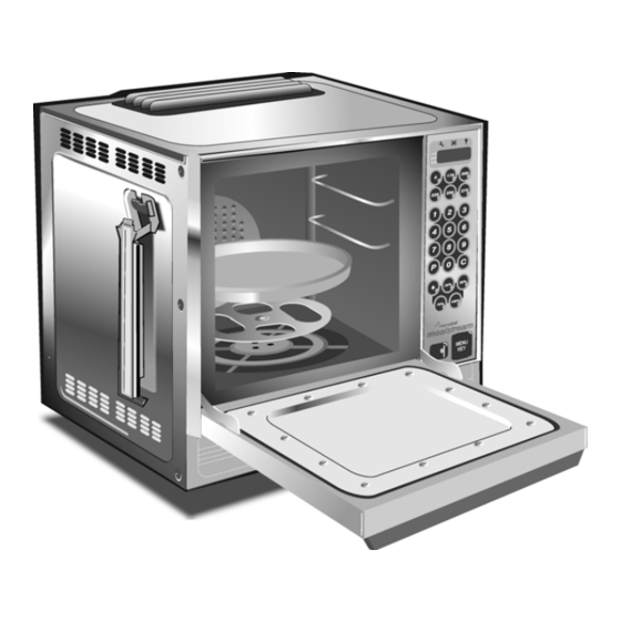
Merrychef mealstream 401 microwave oven
Hide thumbs
Also See for Mealstream 401:
- Instruction manual (19 pages) ,
- Quick reference manual (7 pages)
Table of Contents
Advertisement
Quick Links
Mealstream 401
S E R V I C E
M A N U A L
Part No. 32Z3311 Issue No. 8
For all Mealstream 401 models manufactured from January 2001
CAUTION MICROWAVE EMISSIONS
DO NOT BECOME EXPOSED TO EMISSIONS FROM THE MICROWAVE
GENERATOR OR PARTS CONDUCTING MICROWAVE ENERGY
Mealstream 401Ovens 32Z3311 Issue 8
Page 1
Advertisement
Table of Contents

Related Manuals for Merrychef Mealstream 401


Summary of Contents for Merrychef Mealstream 401
- Page 1 S E R V I C E M A N U A L Part No. 32Z3311 Issue No. 8 For all Mealstream 401 models manufactured from January 2001 CAUTION MICROWAVE EMISSIONS DO NOT BECOME EXPOSED TO EMISSIONS FROM THE MICROWAVE...
-
Page 2: Table Of Contents
Manual corrections and modifications .........37 Merrychef Limited, Station Road West, Ash Vale, Aldershot Hampshire GU12 5XA United Kingdom Tel: +44 (0)1252 371000 Fax: +44 (0)1252 371007 Internet address: http://www.merrychef.com E-mail: sales@merrychef.com or service@merrychef.com Mealstream 401Ovens 32Z3311 Issue 8 Page 2... -
Page 3: Safety Code
Note: the On/Off switch on the oven is not adequate protection against electric shock, as it does not isolate all of the internal wiring from the mains. Upon completion of a service on a Mealstream 401 oven, or before reconnecting the appliance to the mains supply for testing, check all of the following points: •... -
Page 4: Product Specifications
Product specifications ELECTRONIC CONTROLS Model Number: RMC1003 + Voltage + Frequency + Current + Controls + Phase For example: RMC100345XE52 Model Mealstream 401, 230-240V, 50Hz, 30A, Series 5 Controls, Twin Phase Model prefix Voltage Frequency Current, Output, Heater Control Supply... -
Page 5: Principles Of Operation
Principles of operation Mealstream 401Ovens 32Z3311 Issue 8 Page 5... -
Page 6: Installation Instructions
Installation instructions Positioning the Oven In order to maintain adequate ventilation for air intake and exhaust, and to allow access for cleaning filters, you must allow a minimum of 50mm clearance at the sides and rear of the oven, and at least 150mm above. Air intake temperature should not exceed 35°C. Excessive temperature will lead to reduced operating duty cycle or premature ageing of internal components. -
Page 7: Electrical Installation
The Circuit Breaker should be rated at 45A (TypeC). TWIN PHASE Models RMC1003__XE52, RMC1003__XX52 The Mealstream 401 oven Twin Phase models should be connected as shown in Diagram 2. The Circuit Breaker should be rated at 45A (TypeC). Simplified loading Diagram... -
Page 8: Error Codes And Diagnostics
Error codes and diagnostics The Mealstream EC401 will identify some of the most common problems by flashing an error message code in the time display window. Error Message Possible Cause Service Door not fully shut Close door fully. Possible electrical fault Check Microswitch Door Circuit Check Microswitch Connection to PCB Check Ribbon Cable... -
Page 9: Main Features
Main features rear view of Oven a STEAM OUTLET h TURNTABLE TRAY Allows steam and excess pressure to escape The vitreous enamelled turntable tray fits onto the from the oven cavity. It must be kept clear. turntable disc in the bottom of the oven cavity, and rotates during cooking to ensure an even b AIR OUTLET distribution of microwave energy. -
Page 10: Electronic Controls
Electronic controls: Mealstream EC401 Stage LED's Service Indicator Air Filter Block Indicator Operator error indicator Program Display Temperature Set Pads Time / Program Number Pads Cancel/ Callback Pad Program Pad Convection Pad Microwave power Pads On/Off switch m MenuKey socket 100% Starbucks model Mealstream 401Ovens 32Z3311 Issue 8... -
Page 11: Manual Controls
Manual controls: Mealstream RD401 Temperature Amber Neon Temperature Control Microwave Power Control Timer Start Pushbutton Cook cycle Red Neon Power Amber Neon On/Off switch Mealstream 401Ovens 32Z3311 Issue 8 Page 11... -
Page 12: Power Output Testing To En 60335-2-90
Procedure A - Power Output Test In accordance with BS EN 60335-2-90 This test is given in the BSI test standard for microwave ovens. It is reproduced below - not so that you can follow it, but to show you why it is impractical in normal conditions. A simplified procedure, which gives a good approximation to the BSI power output, is given in Procedure B which follows. -
Page 13: Power Output Testing
Procedure B - Simplified Power Output Test You will need: A thermometer capable of reading to ±0.1°C. A Polypropylene tray approximately 200 mm x 200 mm. A measuring jug. A calculator. Water which is at a temperature of 10°C ± 2°C. Measure 1 litre of cold water into the tray using the measuring jug. -
Page 14: High Voltage Capacitor Test
Procedure D - High Voltage Capacitor Test You will need: A Digital Multi-meter (D.M.M.) A Megger or similar resistance meter using 500V d.c. WARNING: High voltages and large currents are present at the High Voltage Capacitor. It is very dangerous to work near this part when the oven is on. NEVER make any voltage measurements at the High Voltage circuits, including the magnetron filament . -
Page 15: Door Interlock Operation
Door interlock operation The door on the Mealstream 401 oven is monitored by four microswitches. Three of these are used in the conventional “Primary, Secondary and Monitor” switch arrangement shown below, while the fourth is a low-voltage switch linked directly to the control circuitry. -
Page 16: Casework
Principal components: casework 105A Handle Hanger RCK6319 Side Panel (L/H) MC3134 Rubber Foot RMC6104 Ferrit RMC6773 Upper Trim MC3120X01 Front Lower Panel MC3047 Top Plate RMC6759E Lower Trim MC3122 Exhaust Gallery RMC73372 PCB Retainer LH 40H0083 Rear Panel MC3129 PCB Retainer RH 40H0084 Air Filter MC3155... -
Page 17: Door Mechanism
Door mechanism Door Stay (R/H) MC3040 Hinge Body MC30121X02 Hook (A) RMC66171 Hook (B) RMC66172 Door Spring (B) MC3068X01 Hinge Body (L/H) MC30122X01 Door Spring (A) MC3067 Door Stay (L/H) MC3046 Microswitch Guide 40H0076 Solid Door Assy Black 11H0071 Solid Door Assy Silver 11H0031 Mealstream 401Ovens 32Z3311 Issue 8 Page 17... -
Page 18: Oven Cavity Components & Hot Air System
Oven cavity components and hot air system Turntable Disc RMC7340X01 31 Gearbox MC3216 Baffle Plate Bolt CP30326 32 Shaft RMC7391X01 Baffle Plate MC3018 33 Cooling Fan RMC7310 Fan Fixing Cap RCK7617 34 Motor Bracket RMC7307X01 MC3111 35 Cushion Rubber RCK8273 Partition Plate 11H0007 36 Motor Fixing Screw... -
Page 19: Oven Door Assembly
Oven door assembly Solid door assembly, Silver 11H0031 Solid door assembly, Black 11H0071 Solid Door Assy. Silver 11H0031 Solid Door Assy Black 11H0071 Door Handle Silver RBR1285048 Door Handle Black RBR12852 Door Frame (A) Black MC30503 Door Cover Outer Silver 40H0080 Door Cover Outer Black 40H0082... -
Page 20: Magnetron & Door Interlock Components
Magnetron and door interlock components Model RMC1003__EE5 Model RMC1003__XE5 54 Door Switch Bracket 40H0023 62 Inlet Duct RMC7193X01 Primary Microswitch 30Z0240 63 Magnetron 30Z0264 Low Voltage Microswitch 30Z0240 64 Magnetron Cut-out 30Z0088 Secondary Microswitch 30Z0240 65 Switch Bracket RMC7101X01 Monitor Microswitch 30Z0240 66 Blower Assembly MC3141... -
Page 21: Magnetron & Door Interlock Components
Magnetron and door interlock components Model RMC1003__XX5 Model RMC1003__XX52 64 Magnetron Cut-out 30Z0088 54 Door Switch Bracket 40H0023 Primary Microswitch 30Z0240 65 Switch Bracket RMC7101X01 Low Voltage Microswitch 30Z0240 67 M3 x 25 Pan Head Pozi 31Z3093 Secondary Microswitch 30Z0240 68 M3 x 30 Pan Head Pozi 31Z3118 128 Cooling Fan 220/240V... -
Page 22: Major Electrical Components
Major electrical components *Not RMC1003__XX5/XX52 See Page 23 64 Magnetron Overheat Switch 30Z0088 74 Temperature Sensor 50E123 69 Cavity Overheat Switch 30Z1031 75 HV Diode Assembly 11H0010 70 Bridge Rectifier (__EE only) 341520 76 HT Capacitor 1.1µ (50Hz) 30Z1077 71 No. 8 Screw 31Z3107 76 HT Capacitor 0.88µ... -
Page 23: Input Wiring, Filters And Fuses
Input wiring, filters and fuses Model RMC1003__XE5, XD Model RMC1003__EE5, CD2 Green / Yellow Green / Yellow Blue Blue Brown Brown 112a 111 Mains Input Block 31Z0328 112 Cable Gland 31Z1070 112A Cable Gland Nut 31Z1082 113 Input Cable Assembly 31Z0220 115 XE5 Input Cable Assembly 302030... -
Page 24: Input Wiring, Filters And Fuses
Input wiring details: Model RMC1003__XX5, XX52 Green / Yellow Green / Yellow Blue Blue Brown 112a 111 Mains Input Block 31Z0328 112 Cable Gland 31Z1070 112A Cable Gland Nut 31Z1082 113 Input Cable Assembly 31Z0220 115 XE5 Input Cable Assembly 302030 116 Strain Relief Grommet 31Z1036... -
Page 25: Ht Components
HT Components: RMC1003__EE5/ XE5 75 HV Diode Assembly 11H0010 76 HT Capacitor 1.1µ (50Hz) 30Z1077 76 HT Capacitor 0.88µ (50Hz) 30Z1075 76 HT Capacitor 0.6µ (60Hz) 30Z0385 76 HT Capacitor 0.74µ (60Hz) 30Z0377 88 HT Transformer Top Bracket MC3127 89 HV Lead Assembly, Ferrit 11H0025 90 HT Transformer 240V 30Z1183... -
Page 26: Ht & Principal Components: Rmc1003
HT & principle components: Models RMC1003__XX5, RMC1003__XX52 Right side 76* HT Capacitor 0.88µF (50Hz) 30Z1075 76* HT Capacitor 0.6µF (60Hz) 30Z0385 76* HT Capacitor 0.74µF (60Hz) 30Z0377 Transformer 220V 50/ 60Hz 30Z1018 Transformer 220V 60Hz 30Z1192 Transformer 240V 50/ 60Hz 30Z1183 Transformer 240V 60Hz 30Z1191... -
Page 27: Electronic Control Panel Assembly
Electronic control panel assembly 100% Membrane Panel Membrane Panel Menukey Starbucks (Blue) (Red/ Grey) Model Membrane Assy Logic PCB EE5, XE5, XX5 11H0060 11C0285 XX5 Starbucks 11H0024 11C0285 EE5, XE5, XX5 11H0067 11C0066 Menukey XX5 Locare 11H0073 11C0066 95 Membrane Assy See Table 103 Relay Assy. -
Page 28: Manual Controls Panel Assembly
Manual control panel assembly 105A 124A 124B 124C 124D On/Off Switch 30Z0503 PCB Retainer RH 40H0084 Side Trim LH MC31211 105A Side Trim RH MC31212 M5 Flat Washer 31Z5004 PCB Assembly 11H0027 Timer 30Z0991 Amber Neon 316031 124A Control Knob Black 313020 124B Control Knob Skirt Red 313160... -
Page 29: Membrane Panel Circuit
Membrane panel circuit You will need: A Digital Multi-meter (D.M.M.) 1. Isolate the oven from the mains supply. 2. Remove the Logic Assembly from the Control Panel Housing. 3. Unplug the membrane “tail” from the Logic PCB Assy. 4. Using a D.M.M., check for continuity between the correct terminals when the pads are pressed. -
Page 30: Complete Spare Part Listing
Part number identification chart 1 SIDE PANEL (L/H) MC3134 INSULATION PANEL 40H0081 FERRITE RMC6773 DOOR REINFORCEMENT RMC70722 UPPER TRIM MC3120X01 DOOR FRAME (B) MC3055 TOP PLATE RMC6759E INSULATION WRAP 32Z0001 EXHAUST GALLERY RMC73372 DOOR BASE SILVER MC3031KX04 REAR PANEL MC3129 DOOR COVER MC3064 GREASE FILTER... - Page 31 Part number identification chart 2 80mm Axial Fan 310010 M’WAVE MAINS FILTER 16A 30Z0997 HEATER MAINS FILTER 16A 30Z0997 PCB Assembly 11H0027 Timer 30Z0991 FUSE COVER 20Z1080 Neon Amber 316031 FUSE 10A HRC 30Z0217 124A Control Knob Black 313020 FUSE HOLDER 1” 30Z0231 124B Control Knob Skirt Red...
-
Page 32: Circuit Diagrams
Circuit diagram: RMC 1003__5 EE & RMC 1003__XE Mealstream 401Ovens 32Z3311 Issue 8 Page 32... -
Page 33: Circuit Diagram
Circuit diagram: RMC 1003__XX5 (Single Phase) Mealstream 401Ovens 32Z3311 Issue 8 Page 33... -
Page 34: Circuit Diagrams
Circuit diagram: RMC 1003__XX52 (Twin Phase) Mealstream 401Ovens 32Z3311 Issue 8 Page 34... -
Page 35: Appendix 1 Menukey Download Procedure
APPENDIX 1 : MenuKey Download Procedure The MenuKey™ System automatically changes all the cooking programs on the numbered icon pads with the turn of a key. To change the menus on the oven: Ensure the power switch is off. Lift the MenuKey cover in the front panel of the oven and put the key in the keyhole Turn the key clockwise to the... -
Page 36: Appendix 2 Cleaning Procedure
APPENDIX 2: Cleaning Procedure For the oven to operate at peak efficiency, the cavity, door and air filters must be kept clean. A daily cleaning routine will ensure that you comply with the required hygiene standards and will help to maintain and prolong the efficiency of your oven. Follow the SAFETY INSTRUCTIONS at the beginning of this manual. -
Page 37: Manual Corrections And Modifications
Name Address Page on which error occurs (if applicable) - Mealstream 401 Series Description of error Suggestion for improvement to manual Please return this form to:...
Need help?
Do you have a question about the Mealstream 401 and is the answer not in the manual?
Questions and answers