
Summary of Contents for X Models Blade XL
- Page 1 & SUPER BLADE On the cover picture the carbon fiber version is shown BUILDING INSTRUCTIONS - OPERATING MANUAL Nuova FULCRO Service Via Castelleone, 9 - Costa S. Abramo - 26022 Castelverde - CR (ITALY)
- Page 2 Blade XL V.: 4.0 ENG - 01/05/2007 Copyright Nuova FULCRO Service No parts of this document can be copied neither shared with any media without the author’s per- mission. Nuova FULCRO Service reserves the right to modify this document according to technical im-...
-
Page 3: Table Of Contents
INDEX INDEX Blade XL .................1 Features......................1 Technical data ....................2 CHAP. 1 PARTS LIST, MATERIALS AND TOOLS LIST....3 1.1 Warning ..................3 1.2 Components included in the kit ........... 3 1.3 Parts needed to complete the kit, but not included ..... 4 List of parts you will need to complete the model ......... - Page 4 Installing bushes for control horns..............24 Electrical connection for the wing servos ............26 Mounting servos inside the wing ..............29 Wing pushrods....................30 Servo covers....................31 2.5 Tail connection ................32 Mounting the tail panels.................32 2.6 Nose ....................32 2.7 Connecting wing panels and tailplanes to the fuselage ....33 CHAP.
-
Page 5: Blade Xl
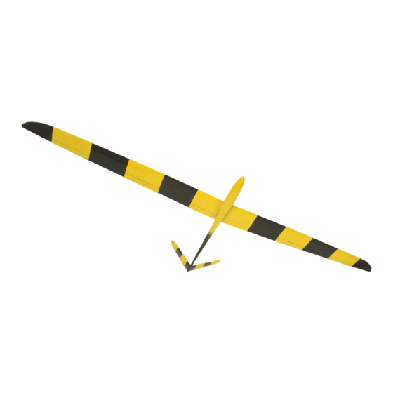
RG15 (7.8%), to offer high performance and a very broad flying speed range; fiberglass carbon reinforced fuselage suited for slope soaring and towing. Two different wingspans are available: (XL) 2.5 m or (SUPER) ~ 3.1 m. Fig.1: Blade XL (& SUPER BLADE). -
Page 6: Technical Data
X-MODELS - Blade XL & SUPER BLADE Technical data Wingspan (XL 2.5 / SUPER 3.1): 2500 / 3080 mm Length: 1510 mm Weight - XL 2.5 version (empty / in flight): about 1400 g / 2100 g Weight - SUPER 3.1 version (empty / in flight):... -
Page 7: Chap. 1 Parts List, Materials And Tools List
Nuova FULCRO Service CHAP. 1 PARTS LIST, MATERIALS AND TOOLS LIST 1.1 Warning DO NOT EXPOSE THE MODEL TO HIGH TEMPERATURES. Exposing the model (or its parts) to high temper- ° atures, over 50 C (example: in a car parked directly in the sun) may deform structures and make it unus- able. -
Page 8: Parts Needed To Complete The Kit, But Not Included
X-MODELS - Blade XL & SUPER BLADE Decal If you like, you may stick the decal we supply with the kit (see figure Fig.2: Decal “Blade XL”. 1.3 Parts needed to complete the kit, but not included These are the parts you will need to complete the model (see “List of parts you will need to com-... -
Page 9: More Options
Nuova FULCRO Service More options Wings and fuselage made of carbon fiber On request, wing, tailplanes and fuselage are available completely made of carbon fiber. The model, made in this way, offers more torsional strength and an exceptional sturdiness. The fuselage (see figure 3) is painted like the model but with the rear part unpainted (made to save weight without to reduce the strength). -
Page 10: Tools And Materials Needed (Not Included) To Complete The Kit
X-MODELS - Blade XL & SUPER BLADE 1.4 Tools and materials needed (not included) to complete the kit Tools These tools may help you while assembling the kit: — electric drill (and various size drill bits); — modelling knife (or scapel);... -
Page 11: Chap. 2 Building Instructions
Nuova FULCRO Service CHAP. 2 BUILDING INSTRUCTIONS In order to achieve a correct assembling of the model, we suggest to follow carefully the instructions. 2.1 Preliminary operations Kit components control Have a look at the components (see “PARTS LIST, MATERIALS AND TOOLS LIST” at page 3) in order to easily identify them. -
Page 12: Battery Pack
X-MODELS - Blade XL & SUPER BLADE Battery pack • Cover the weights of epoxy (or hot glue) in order to form a uniform layer; • cut a strip of velcro (8 x 4 cm); • separate the velcro soft strip from the rough one;... -
Page 13: Servos And On/Off Switch
Nuova FULCRO Service Servos and ON/OFF switch • Try to insert the servos mounting frame “BASE” in the fuselage as shown in figure 11 without forcing too much and WITHOUT GLUING IT. Fig.11: Position of the servos mounting frame. If the frame doesn’t fit: •... -
Page 14: Positioning Battery Pack And Servos
X-MODELS - Blade XL & SUPER BLADE • drill 1.5 mm diameter hole on the marked points (see figure 14); • using a knife, make the ON/OFF switch housing; Fig.14: Drill the marked points. • mount the two servos on the frame as... -
Page 15: Preparing And Mounting Servo Horns
Nuova FULCRO Service Preparing and mounting servo horns Preparing horns For each servo horn: • Using side cutters, cut the servo horns in surplus (see figure 18). Fig.18: Cut the servo horns in surplus. • drill 1.5 mm diameter hole in order to widen the servo horn hole (see figure 19). -
Page 16: V-Tail
X-MODELS - Blade XL & SUPER BLADE 2.3 V-tail Finishing tail insertion holes • Using a drill bit 6 mm diameter (larger than the holes), trim exceeding metal edges from the tail insertion holes (see figure 21); Fig.21: Trim exceeding metal edges. -
Page 17: Finishing Tail Panels
Nuova FULCRO Service Finishing tail panels Tail panels support pins • Using a pair of pliers, bend a little bit the two tail connection pins in order to make them slightly diverging (see figure 25); this opera- tion will avoid the tail to slip out from its sup- ports during the flight;... -
Page 18: Pushrods
X-MODELS - Blade XL & SUPER BLADE Pushrods • using side cutters, cut two metal pushrods “AMR2” at a length of 100 mm; • cut the other two metal pushrods “AMR2” a length of 150 mm; • using side cutters, carefully make some dents in the (non threaded part of the) rod “AMR2”, for a length of 5 cm, in order to in-... - Page 19 Nuova FULCRO Service • insert the front pushrod groups into the elevator pushrods “CARB” WITHOUT GLUING THEM (see figure 32); Fig.32: Inserting front pushrod groups (without gluing them). • insert the two complete pushrod groups into the fuselage (see figure 33);...
- Page 20 X-MODELS - Blade XL & SUPER BLADE • using some masking tape, keep the V-tail movable control surfaces aligned (see figure 36); Fig.36: Keeping control surfaces aligned. • connect the clevises to the servos horns in fuselage; • using a fibre-tip pen, mark the position of the...
-
Page 21: Electrical Connections For Wing Servos
Nuova FULCRO Service Electrical connections for wing servos The electrical connection between wing servos and receiver is made with a set of connectors like the ones shown in figure • Take the external dimensions of the “MPXF” connector. MPXF Fig.39: Wing servos connectors set. MPXM Preparing electrical connections Each RX connector... - Page 22 X-MODELS - Blade XL & SUPER BLADE Holes for the wing servos connections • At a distance of 40 mm from the alignment hole (see figure 42), using a knife (with a well sharpened blade), make a hole having the same dimensions of the “MPXF”connector;...
- Page 23 Nuova FULCRO Service • insert a wing-panel (see figure 45); Fig.45: Inserting a wing-panel. • using a pencil lead or a metal scriber (at least 6 cm long), mark the shape on the wing root tracing it from the hole already done (see figure 46);...
- Page 24 X-MODELS - Blade XL & SUPER BLADE Preparing electrical connections • Insert the cables (from the side of the RX connectors) into the hole made in the fuse- lage (see figure 48); Fig.48: Inserting RX connectors. • insert the cables up to the socket “MPXF”...
-
Page 25: Receiver
Nuova FULCRO Service Receiver The receiver must be protected against possible shocks due to hard landings: • cut two strips of polyethylene (5 mm thick) and, using some tape, fasten them, over and under the RX (see figure 51); Fig.51: One strip over and the other under the RX. •... - Page 26 X-MODELS - Blade XL & SUPER BLADE • insert the receiver “RXC6” into the fuselage, behind servos, as shown in figure Fig.54: Positioning the receiver. • position the receiver as shown in figure Fig.55: Final position of the receiver. • plug the RX plugs to the receiver according...
-
Page 27: Antenna
Nuova FULCRO Service figure 57 is shown the final look of the fuselage internal components. Fig.57: Final look of the fuselage internal components. Antenna Because of the fuselage’s reinforcements and the elevator push-rods, both in carbon fiber, we suggest to leave the antenna outside the fuselage. For the best reception signal, the position we recommend is the one shown in figure Fig.58: Antenna’s (recommended) position. -
Page 28: Wing
X-MODELS - Blade XL & SUPER BLADE 2.4 Wing The wing is divided in two panels, each one equipped with aileron and flap. Flaps and ailerons servos are fitted into the wings. For this reason, each wing panel is fitted with two rectangular housings where servos can be mounted. - Page 29 Nuova FULCRO Service Holes for wing servos connection • Using a drill (3 mm diameter), make some holes inside the marked part (see figure 62); Fig.62: Make some holes inside the marked part. • using a knife (with a well sharpened blade) remove all the material inside the wing in or- der to make enough space for the connector (see figure...
-
Page 30: Electrical Connection For The Wing Servos
X-MODELS - Blade XL & SUPER BLADE Electrical connection for the wing servos The the wing servos connection needs just four wires to connect following the diagram shown in figure Fig.65: Connection diagram for the wing servos (the same for the other wing). - Page 31 Nuova FULCRO Service Flap servo • Using side cutters, remove the RX connector of the servo; • cut and strip, for a length of about 10 mm, the three wires coming from servo; • strip the black and the red wire coming from the wing for a length of 10 mm, but, WITH- OUT CUTTING THEM;...
- Page 32 X-MODELS - Blade XL & SUPER BLADE Servos test Before to mount the wing servos, will be better to check the connections: • connect servos (and ON/OFF switch) to the receiver following the diagram shown in figure 88 at page •...
-
Page 33: Mounting Servos Inside The Wing
Nuova FULCRO Service Mounting servos inside the wing For each wing servo “SERW”: • shorten the horn of (at least) two holes (see figure 69); Fig.69: Shorten the horn. • fasten the horn to the servo; • remove protection film and apply the double adhesive plate to the servo (see figure 70);... -
Page 34: Wing Pushrods
X-MODELS - Blade XL & SUPER BLADE Wing pushrods For each wing servo: AMR2 DAD2 FOR2 • screw the nut “DAD2” and the clevis “FOR2” on the threaded pushrod “AMR2”; Fig.72: Pushrod, nut and clevis. • screw the threaded horn “PERN”in the bush “BOCC”;... -
Page 35: Servo Covers
Nuova FULCRO Service Servo covers The wing servo covers are made from the shapes “CARS”. From every shape, two covers can be made (left and right): • take the distance from the external edge of the servo housing and the servo horn (see figure 76);... -
Page 36: Tail Connection
X-MODELS - Blade XL & SUPER BLADE 2.5 Tail connection Mounting the tail panels • Mount the tail panels as shown in figure Fig.79: Mounting tail panels. • insert the ball link sockets “GIUN” to the ball joints “UNIB” (see figure 80). -
Page 37: Connecting Wing Panels And Tailplanes To The Fuselage
Nuova FULCRO Service 2.7 Connecting wing panels and tailplanes to the fuselage • Insert the wing rod “BAIO” into its housing (see figure 82); Fig.82: Insert the wing rod. • insert the wing rod in the hole on the root of the wing (see figure 83);... - Page 38 X-MODELS - Blade XL & SUPER BLADE...
-
Page 39: Chap. 3 Model Settings
Nuova FULCRO Service CHAP. 3 MODEL SETTINGS 3.1 Servos settings Identifying the control surfaces Refer to figure — ailerons (roll); — flap (camber changing, crow brake); — tailplanes (pitch - yaw). Fig.84: Control travel. -
Page 40: Travel Values
X-MODELS - Blade XL & SUPER BLADE Travel values These are suggested values, found during our test flights. Just consider these a starting point and feel free to modify the travel values according to your flying skill, style, flying area, etc. -
Page 41: Model Balancing
Nuova FULCRO Service 3.2 Model balancing The CG of the model must be placed at 83 ~ 88 mm from the wing leading edge at the wing root (see figure 86). 83 ~ 88 mm Fig.85: CG position. Note: You may in a second time move it a little backwards if you feel (and if you are a real good pilot...). Checking and correcting the CG position •... -
Page 42: How To Add Ballast
X-MODELS - Blade XL & SUPER BLADE • gently leave the model alone (see figure 86); Fig.86: Checking for lateral balance. • repeat this more times. Correcting If the same wing half drops all the times: • add some lead pellet to the lighter wing (you can place the lead in the servo hole) until satis- fied (usually a few grams do the job);... -
Page 43: Chap. 4 Connections Diagrams
Nuova FULCRO Service CHAP. 4 CONNECTIONS DIAGRAMS Here are shown the complete connection diagrams (with battery pack, ON/OFF switch, receiver and servos) for each version of the model. Note: the connection to the receiver outputs depends from the radio control type and receiver you are using. Fig.88: Electrical connections.
Need help?
Do you have a question about the Blade XL and is the answer not in the manual?
Questions and answers