Table of Contents
Troubleshooting

Subscribe to Our Youtube Channel
Related Manuals for Miller XR-D Control


Summary of Contents for Miller XR-D Control
- Page 1 OM-245778P 2016−05 Processes MIG (GMAW) Welding Description Wire Feeder And Feeder Gun ™ XR - D Control For product information, File: MIG (GMAW) Owner’s Manual translations, and more, visit www.MillerWelds.com...
- Page 2 We know you don’t have time to do it any other way. That’s why when Niels Miller first started building arc welders in 1929, he made sure his products offered long-lasting value and superior quality.
-
Page 3: Table Of Contents
TABLE OF CONTENTS SECTION 1 − SAFETY PRECAUTIONS - READ BEFORE USING ........1-1. -
Page 4: Declaration Of Conformity
DECLARATION OF CONFORMITY for European Community (CE marked) products. MILLER Electric Mfg. Co., 1635 Spencer Street, Appleton, WI 54914 U.S.A. declares that the product(s) identified in this declaration conform to the essential requirements and provisions of the stated Council Directive(s) and Standard(s). -
Page 5: Section 1 − Safety Precautions - Read Before Using
SECTION 1 − SAFETY PRECAUTIONS - READ BEFORE USING som 2015−09 Protect yourself and others from injury — read, follow, and save these important safety precautions and operating instructions. 1-1. Symbol Usage DANGER! − Indicates a hazardous situation which, if Indicates special instructions. - Page 6 D Remove stick electrode from holder or cut off welding wire at FUMES AND GASES can be hazardous. contact tip when not in use. D Wear body protection made from durable, flame−resistant material Welding produces fumes and gases. Breathing (leather, heavy cotton, wool). Body protection includes oil-free these fumes and gases can be hazardous to your clothing such as leather gloves, heavy shirt, cuffless trousers, high health.
-
Page 7: Additional Symbols For Installation, Operation, And Maintenance
1-3. Additional Symbols For Installation, Operation, And Maintenance FIRE OR EXPLOSION hazard. MOVING PARTS can injure. D Do not install or place unit on, over, or near D Keep away from moving parts such as fans. combustible surfaces. D Keep all doors, panels, covers, and guards D Do not install unit near flammables. -
Page 8: California Proposition 65 Warnings
1-4. California Proposition 65 Warnings Welding or cutting equipment produces fumes or gases This product contains chemicals, including lead, known to which contain chemicals known to the State of California to the state of California to cause cancer, birth defects, or other cause birth defects and, in some cases, cancer. -
Page 9: Section 2 − Consignes De Sécurité − Lire Avant Utilisation
SECTION 2 − CONSIGNES DE SÉCURITÉ − LIRE AVANT UTILISATION fre_som_2015−09 Pour écarter les risques de blessure pour vous−même et pour autrui — lire, appliquer et ranger en lieu sûr ces consignes relatives aux précautions de sécurité et au mode opératoire. 2-1. - Page 10 chauffement ou un incendie. Avant de commencer le soudage, vérifier LES PIÈCES CHAUDES peuvent et s’assurer que l’endroit ne présente pas de danger. provoquer des brûlures. D Déplacer toutes les substances inflammables à une distance de D Ne pas toucher à mains nues les parties chaudes. 10,7 m de l’arc de soudage.
-
Page 11: Dangers Supplémentaires En Relation Avec L'installation, Le Fonctionnement Et La Maintenance
D Placer les bouteilles debout en les fixant dans un support station- déroule du soudage à l’arc, du soudage par points, du gougeage, de la découpe plasma ou une opération de chauffage par naire ou dans un porte-bouteilles pour les empêcher de tomber ou induction. -
Page 12: Proposition Californienne 65 Avertissements
D N’utiliser que les pièces de rechange recommandées par le LE SOUDAGE À L’ARC risque de constructeur. provoquer des interférences. D Effectuer l’installation, l’entretien et toute intervention selon les manuels d’utilisateurs, les normes nationales, provinciales et de D L’énergie électromagnétique risque l’industrie, ainsi que les codes municipaux. -
Page 13: Section 3 − Definitions
SECTION 3 − DEFINITIONS 3-1. Additional Safety Symbols And Definitions Some symbols are found only on CE products. Warning! Watch Out! There are possible hazards as shown by the symbols. Safe1 2012−05 Do not discard product (where applicable) with general waste. Reuse or recycle Waste Electrical and Electronic Equipment (WEEE) by disposing at a designated collection facility. - Page 14 Do not weld on drums or any closed containers. Safe64 2012−06 Do not remove or paint over (cover) the label. Safe20 2012−05 Drive rolls can injure fingers. Safe32 2012−05 Welding wire and drive parts are at welding voltage during operation − keep hands and metal objects away. Safe33 2012−05 Wear hat and safety glasses.
-
Page 15: Miscellaneous Symbols And Definitions
3-2. Miscellaneous Symbols And Definitions Some symbols are found only on CE products. Circuit Breaker Amperes Primary Voltage Trigger Volts Rated Current Alternating Cur- Trigger Hold On rent Fuse Duty Cycle MIG-Start Percent Degree Of Wire Feed Protection Load Voltage Line Connection Press To Set Trigger Hold Off... -
Page 16: Section 4 − Specifications
SECTION 4 − SPECIFICATIONS 4-1. Serial Number And Rating Label Location The serial number and rating information for this product is located on the rear panel. Use rating label to determine input power requirements and/or rated output. For future reference, write serial number in space provided on back cover of this manual. 4-2. -
Page 17: Section 5 − Installation
SECTION 5 − INSTALLATION 5-1. Connections With A Constant Voltage (CV) Or Constant Current/Constant Voltage (CC/CV) Welding Power Source Having A 14-Socket Receptacle Ref. 245 997-A / 151 666-G 24 VAC/Contactor Control 14-Pin Positive (+) Weld Cable Turn Off wire feeder and welding Plug power source. -
Page 18: Air-Cooled Feeder Connections
5-2. Air-Cooled Feeder Connections Gas Fitting Connect one end of 10 ft (3 m) gas hose to rear of unit, gas solenoid fit- ting. Connect remaining end of hose to regulator/flowmeter. Shielding gas pressure not to exceed 100 psi (689 kPa). Weld Cable To Welding Power Source Select and prepare weld cable... -
Page 19: Air-Cooled Gun Connections
5-3. Air-Cooled Gun Connections Left Side Ref. 245 995-A / 246 218-A / 151 666-G Gun Control Cable Gun Bushing Loosen gun securing knob and insert gun power pin through gun bushing until it Insert plug into Gun Control receptacle, and Gun Securing Knob bottoms against drive casting. -
Page 20: Water-Cooled Feeder Connections
Distilled Or Deionized Water OK ° ° Above 32 F (0 Coolant *HF: High Frequency Current ° ° **MILLER coolants protect to -37 F (-38 C) and resist algae growth. Tools Needed: 9/16 in. Ref. 246 218-C OM-245778 Page 16... -
Page 21: Water-Cooled Gun Connections
5-5. Water-Cooled Gun Connections Turn on coolant supply before welding or gun will be dam- aged. Gun Control Cable Insert plug into Gun Control receptacle, and tighten threaded collar. Gun Power Pin Gun Securing Knob Gun Bushing Drive Casting Loosen gun securing knob, and insert gun power pin through gun bushing until it bottoms against drive casting. -
Page 22: 14-Pin Plug Information
5-6. 14-Pin Plug Information Pin* Pin Information 24 volts AC with respect to socket G. Contact closure to A completes 24 volts AC contactor control circuit. Circuit common for 24 volts AC circuit. +10 volts DC input from power source to wire feeder with respect to socket D. Remote control circuit common. -
Page 23: Threading Welding Wire Through Feeder
5-8. Threading Welding Wire Through Feeder Hold wire tightly to keep it from unraveling. 6 in. (150 mm) Pull and hold wire; cut off end. Tension Arm Open tension arm. Install proper size drive rolls. Thread wire thru inlet guide, along drive roll groove, and into wire conduit. -
Page 24: Section 6 − Operation
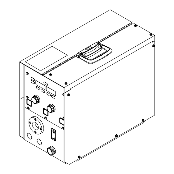
SECTION 6 − OPERATION 6-1. Front Panel Controls SETUP START CRATER SETUP START CRATER JOG / PURGE WATER IN WATER OUT GUN CONTROL 805 354-A Start Button Volts Indicator 13 Wire Speed Indicator Setup Button Crater Menu Indicator 14 Amps Indicator Setup Indicator Start Menu Indicator 15 Right Adjust Knob... -
Page 25: Jog/Purge
6-2. Jog/Purge Pressing the Jog/Purge switch allows the activated, the feeder will perform a jog op- is set to for welding. operator to jog wire without energizing the eration for a maximum of 2 minutes. If the S Jogging can also be accomplished by weld power or gas valve circuit. -
Page 26: Operational Terms
6-4. Operational Terms The following is a list of terms and their definitions as they apply to the wire feeder: General Terms: CV weld process with individual settings of voltage and wire speed. Pulsed MIG CC weld process with factory taught data using peak and background current, pulse width and pulses per second. -
Page 27: Setting A Start Sequence
7-3. Setting A Start Sequence To turn on a Start sequence, press the Rotate the LEFT ADJUST KNOB to select Start Voltage (VOLT) − Sets the voltage START button. START different menu items shown in the LEFT during the Start Time. Range of this setting INDICATOR will illuminate indicating Start DISPLAY. -
Page 28: Setting A Crater Fill Sequence
7-4. Setting A Crater Fill Sequence To turn on Crater Fill, press the CRATER KNOB to change menu item values shown Crater Ramp Time (RAMP) − The amount button. The CRATER ON INDICATOR will in the RIGHT DISPLAY. of time it takes to transition from the weld to illuminate indicating Crater Fill is active. -
Page 29: Section 8 − Maintenance & Troubleshooting
SECTION 8 − MAINTENANCE & TROUBLESHOOTING Maintain more often Disconnect power before maintaining. during severe conditions. 3 Months Clean Replace Damaged Or Replace Damaged Tighten Gas Hose Unreadable Weld Labels Terminals Repair Or Replace Cracked Cables And Cords 6 Months Clean Blow Out Or Drive... -
Page 30: Replacing Hub Assembly
8-2. Replacing Hub Assembly Remove gun top cover and release pressure arm. Retract wire onto spool and remove spool. Take hub apart as shown. Metal Brake Washer Fiber Washer Brake Washer Keyed Washer Spring Flat Washer Cap Screw Retaining Ring Replace broken or worn parts and slide parts onto shaft as shown. -
Page 31: Troubleshooting
8-4. Troubleshooting Disconnect power before troubleshooting. Trouble Remedy Pressing gun trigger does not energize Secure plug from gun control cable into Gun Control receptacle on feeder (see Section 5-3). feeder. Shielding gas does not flow and Have nearest Factory Authorized Service Agent check optional water flow switch, if applicable. wire feeder does not feed. -
Page 32: Section 9 − Electrical Diagrams
SECTION 9 − ELECTRICAL DIAGRAMS Figure 9-1. Circuit Diagram For Wire Feeder OM-245778 Page 28... - Page 33 245 790-C OM-245778 Page 29...
-
Page 34: Section 10 − Parts List
SECTION 10 − PARTS LIST Hardware is common and not available unless listed. Ref. 245 999-C Figure 10-1. Main Assembly OM-245778 Page 30... - Page 35 Item Diagram Part marking Description Quantity Figure 10-1. Main Assembly ....089572 Catch, Link-lock ..........
- Page 36 Item Diagram Part Description marking Quantity Figure 10-1. Main Assembly (Continued) ....254843 Nut, Pg21 1.50 Hex X .375H Aluminum ......
- Page 37 Item Diagram Part Description marking Quantity Figure 10-2. Motor & Wire Drive (Figure 10-1 Item 54) ....242841 Drive Assembly, Wire (Includes) ........
- Page 38 Hardware is common and not available unless listed. 246 000-A Figure 10-3. Front Panel Assembly Item Diagram Part Description marking Quantity Figure 10-3. Front Panel Assembly (Figure 10-1 Item 53) ..... 213134 .
- Page 39 Effective January 1, 2016 (Equipment with a serial number preface of MG or newer) This limited warranty supersedes all previous Miller warranties and is exclusive with no other guarantees or warranties expressed or implied. Warranty Questions? LIMITED WARRANTY − Subject to the terms and conditions below, 6 Months —...
- Page 40 Contact the Delivering Carrier to: File a claim for loss or damage during shipment. For assistance in filing or settling claims, contact your distributor and/or equipment manufacturer’s Transportation Department. © ORIGINAL INSTRUCTIONS − PRINTED IN USA 2016 Miller Electric Mfg. Co. 2016−01...
Need help?
Do you have a question about the XR-D Control and is the answer not in the manual?
Questions and answers