Table of Contents
Advertisement
Quick Links
Advertisement
Table of Contents
Troubleshooting

Related Manuals for Miller XR - AlumaPro


Summary of Contents for Miller XR - AlumaPro
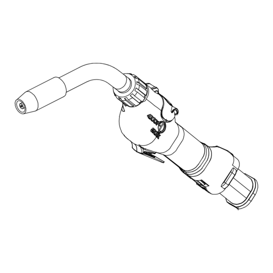
- Page 1 OM-227 398L 2011−05 Processes MIG (GMAW) Welding Description Semi-Automatic, Air-Cooled, MIG (GMAW) Welding Gun ™ XR - AlumaPro (Air-Cooled Guns) 300 Ampere (Air) Push-Pull Welding Gun File: MIG (GMAW) Visit our website at www.MillerWelds.com...
- Page 2 We know you don’t have time to do it any other way. That’s why when Niels Miller first started building arc welders in 1929, he made sure his products offered long-lasting value and superior quality.
-
Page 3: Table Of Contents
TABLE OF CONTENTS SECTION 1 −SAFETY PRECAUTIONS FOR GMAW WELDING GUNS − READ BEFORE USING ..1-1. Symbol Usage ............... . 1-2. -
Page 5: Section 1 −Safety Precautions For Gmaw Welding Guns − Read Before Using
SECTION 1 −SAFETY PRECAUTIONS FOR GMAW WELDING GUNS − READ BEFORE USING SR7 (MIG) 2010−03 Protect yourself and others from injury — read and follow these precautions. 1-1. Symbol Usage DANGER! − Indicates a hazardous situation which, if Indicates special instructions. not avoided, will result in death or serious injury. -
Page 6: Proposition 65 Warnings
1-3. Proposition 65 Warnings Welding or cutting equipment produces fumes or gases This product contains chemicals, including lead, known to which contain chemicals known to the State of California to the state of California to cause cancer, birth defects, or other cause birth defects and, in some cases, cancer. -
Page 7: Utilisation
SECTION 2 − MESURES DE SÉCURITÉ VISANT LES PISTOLETS DE SOUDAGE GMAW − À LIRE AVANT UTILISATION SR7(MIG)_2010−03fre Se protéger, ainsi que toute autre personne travaillant sur les lieux, contre les étincelles et le métal chaud. 2-1. Signification des symboles DANGER! −... -
Page 8: Proposition Californienne 65 Avertissements
Le BRUIT peut endommager l’ouie. LIRE LES INSTRUCTIONS. D Lire et appliquer les instructions sur les Le bruit des processus et des équipements peut étiquettes et Mode d’emploi avant affecter l’ouïe. l’installation, l’utilisation ou l’entretien de D Vérifier si les niveaux de bruit excèdent les lim- l’appareil. -
Page 9: Section 3 − Definitions
SECTION 3 − DEFINITIONS 3-1. Symbols And Definitions Amperes Volts Alternating Current Duty Cycle Degree Of Hertz Circuit Breaker Wire Feed Protection Output Trigger Press To Set Increase Trigger Hold On Trigger Hold Off Purge Spot Weld Time Percent Run-In Burnback Time Primary Voltage Load Voltage... -
Page 10: Section 4 − Introduction
SECTION 4 − INTRODUCTION 4-1. Specifications Model Welding Output Range Electrode Wire Feed Net Weight Wire Diameter Speed Range (Torch Only) Capacity XR-AlumaPro Gun 300 A at 100% Duty Cycle .030 To 1/16 in. 70 To 900 ipm 2.5 lb (1.1 kg) (Air Cooled) with 15, 25 or 35 ft (0.8 To 1.6 mm) -
Page 11: Section 5 − Installation
SECTION 5 − INSTALLATION Be sure that contact tip, liner, and drive rolls are correct for wire size and type. See Parts List to change parts as needed. 5-1. Connections With A Constant Current (CC), Constant Voltage (CV) Or Constant Current/Constant Voltage (CC/CV) Welding Power Source Having A 14-Socket Re- ceptacle XR-D... -
Page 12: Air-Cooled Gun Connections
5-2. Air-Cooled Gun Connections Left Side Ref. 245 995-A / 246 218-A / 151 666-G Gun Control Cable Gun Bushing Loosen gun securing knob and insert gun power pin through gun bushing until it Insert plug into Gun Control receptacle, and Gun Securing Knob bottoms against drive casting. -
Page 13: Threading Welding Wire For Alumapro Gun And Millermatic 350P
5-3. Threading Welding Wire For AlumaPro Gun And Millermatic 350P Wire Spool Welding Wire Inlet Wire Guide Drive Roll Intermediate Wire Guide Outlet Wire Guide Pressure Adjustment Knob Gun Conduit Cable Lay gun cable out straight. Tools Needed: Hold wire tightly to keep it IMPORTANT! from unraveling. -
Page 14: Threading Welding Wire Through Xr-Control Feeder
5-4. Threading Welding Wire Through XR-Control Feeder Cable Assembly Lay cable assembly out straight. Jog Switch Tools Needed: Push Jog switch up to feed wire through cable assembly. Torque Switch Select proper push feeder torque set- ting for wire size being used. Use low torque for .030 in. -
Page 15: Adjusting Tension At Feeder
5-5. Adjusting Tension At Feeder Tools Needed: Hold wire tightly to keep it from unraveling. 6 in. (150 mm) Tension Arm Pull and hold wire; cut off end. Open tension arm. Install proper size drive rolls. Thread wire thru inlet guide, along drive roll groove, and into wire conduit. -
Page 16: 10-Pin Plug Information
5-6. 10-Pin Plug Information Pin* Pin Information Electrode sense lead Motor Common Trigger Motor 0 to +24 volts DC with respect to pin B Trigger Wire speed Ref. +9 volts DC Wire speed com Wire speed 0 to +9 volts DC with respect to pin H Gun sensing resistor with respect to pin H Not used 5-7. -
Page 17: Threading Welding Wire Through Gun
5-8. Threading Welding Wire Through Gun Refer to Section 5-3 for instructions on feeding wire through feeder. For XR-AlumaPro Gun: JOG / PURGE Welding wire is electrically live when gun trigger is used to jog wire. Turn OFF coolant supply before threading wire Lay gun cable out straight. -
Page 18: Section 6 − Operation
SECTION 6 − OPERATION 6-1. Gun Controls Trigger Press trigger to energize welding power source contactor applicable), start shielding gas flow, and begin wire feed. Switches inside the wire feeder can be set to provide timed shielding gas preflow and postflow when trigger is pressed and released. -
Page 19: Shielding Gas
6-3. Shielding Gas Shielding Gas Cylinder Valve Gun Trigger Open valve on cylinder just before welding. Gun trigger turns weld output and gas flow on and off (see Section 6-1). Close valve on cylinder when finished welding. Ref. 151 666-F / 804 545-B 6-4. -
Page 20: Replacing Head Tube Liner In Xr-Alumapro Guns
6-5. Replacing Head Tube Liner In XR-AlumaPro Guns The standard head tube liner (yellow) will accommodate wire diameters from 3/64 in.- 1/16 in. wire size. When changing wire size, change control box drive roll, idler and head tube liner with appropriate sized lin- Head Tube Head Tube Nut Loosen head tube nut and remove... -
Page 21: Replacing The Gun Liner On Xr-Alumapro Guns
6-7. Replacing The Gun Liner On XR-AlumaPro Guns Gun End Refer To Instructions Below. Remove Old Liner (Item 2) From Gun End Install New Liner (Item 2) Into Gun End Power Pin End Gently pry open slots to remove wire collet guide. Cut liner flush with wire collet guide. -
Page 22: Section 7 − Maintenance & Troubleshooting
SECTION 7 − MAINTENANCE & TROUBLESHOOTING 7-1. Routine Maintenance For Aluminum Push/Pull Guns Disconnect power before maintaining. n = Check ~ = Clean l = Replace Daily n~ Head Tube Liner and Drive Casting (see Section 6-5) Weekly n~ Drive Roll Every Spool of Wire... -
Page 23: Cleaning The Gun Liner On Xr-Alumapro Guns
7-2. Cleaning The Gun Liner On XR-AlumaPro Guns Turn Off welding power source and wire feeder. NOTICE − Clean gun liner be- fore cleaning stainless tube and inlet guide. Lay gun cable out straight. Leather Cover Remove leather cover to ac- cess liner assembly. -
Page 24: Troubleshooting Table
7-3. Troubleshooting Table Disconnect power before troubleshooting. Trouble Remedy No wire feed at gun, feeder not operat- Reset circuit breaker in feeder/control box. See feeder/control owner’s manual. ing. Check motor or brake solenoid. Replace trigger-switch and test operation. Check trigger-switch wires for continuity. Reset circuit breaker in feeder/control box and check for short in motor leads. -
Page 25: Section 8 − Electrical Diagrams
SECTION 8 − ELECTRICAL DIAGRAMS 228 669-B Figure 8-1. Circuit Diagram For XR-AlumaPro Gun Notes OM-227 398 Page 21... -
Page 26: Section 9 − Parts List
SECTION 9 − PARTS LIST Hardware is common and not available unless listed. Figure 9-1. Exploded View Of XR-A AlumaPro Gun OM-227 398 Page 22... - Page 27 Ref. 804 511-D Item Part Description Quantity Figure 9-1. Exploded View Of XR-A AlumaPro Gun ... . . 231 519 Kit, Head Tube Assy (Air) Short ........
- Page 28 Item Part Description Quantity Figure 9-1. Exploded View Of XR-A AlumaPro Gun (Continued) ... . . 227 608 Reducer, Guide Liner ..........
- Page 29 Hardware is common and not available unless listed. 804 705-A Figure 9-2. (Air) Head Tube Assembly Of AlumaPro Gun Item Part Description Quantity Figure 9-2. (Air) Head Tube Assembly Of AlumaPro Gun (Figure 9-1 Item 2) ....231 518 Kit, Head Tube Assy Air (Long) (Includes) .
-
Page 30: Section 10 − Parts List Including Consumables
SECTION 10 − PARTS LIST INCLUDING CONSUMABLES Item Number XR-AlumaPro 4” Head Tube Inner Rear (#227 416) Air (Short) (#231 519) Outer XR-AlumaPro Air Short 6” Head Tube (#230 679) (#227 159) .030−1/16” Air (Long) (#231 518) (#229 670) Outer Air Long (#229 673) (#230 678) - Page 31 Table 10-2. Heavy Duty FasTiptContact Tips* ♦206 185 ... .030 in (0.8 mm) ........... . ♦206 186 .
- Page 32 Notes...
- Page 33 Notes SOCKET/WRENCH SELECTION TABLE SOCKET/WRENCH SELECTION TABLE (U.S. STANDARD) (METRIC) Specifications Socket or Wrench Size Specifications Socket or Wrench Size U.S. Bolt Decimal Bolt Bolt Decimal Bolt Diameter Equivalent Diameter Equivalent 1/4 in. .250 in. 3/8 in. 7/16 in. 6 mm .2362 in.
- Page 34 Notes Start Your Professional Over 80,000 trained 400 Trade Square East, Troy, Ohio 45373 Welding Career Now! since 1930! 1-800-332-9448 www.welding.org...
- Page 35 Effective January 1, 2011 (Equipment with a serial number preface of MB or newer) This limited warranty supersedes all previous Miller warranties and is exclusive with no other Warranty Questions? guarantees or warranties expressed or implied. LIMITED WARRANTY − Subject to the terms and conditions 90 Days —...
- Page 36 Contact the Delivering Carrier to: File a claim for loss or damage during shipment. For assistance in filing or settling claims, contact your distributor and/or equipment manufacturer’s Transportation Department. © ORIGINAL INSTRUCTIONS − PRINTED IN USA 2011 Miller Electric Mfg. Co. 2011−01...
Need help?
Do you have a question about the XR - AlumaPro and is the answer not in the manual?
Questions and answers