Miller XMT 304 Owner's Manual
4-rack and 6-rack
Hide thumbs
Also See for XMT 304:
- Technical manual (78 pages) ,
- Owner's manual (40 pages) ,
- Owner's manual (37 pages)
Table of Contents
Troubleshooting

Related Manuals for Miller XMT 304


Summary of Contents for Miller XMT 304
- Page 1 OM-818 183 577A December 1996 Processes Multiprocess Welding Description Mounting Rack For XMT 304 Welding Power Sources XMT 304 4-Rack And 6-Rack Visit our website at www.MillerWelds.com...
-
Page 3: Table Of Contents
TABLE OF CONTENTS SECTION 1 − SAFETY PRECAUTIONS - READ BEFORE USING ......1-1. -
Page 5: Section 1 − Safety Precautions - Read Before Using
SECTION 1 − SAFETY PRECAUTIONS - READ BEFORE USING som _nd_5/97 1-1. Symbol Usage Means Warning! Watch Out! There are possible hazards with this procedure! The possible hazards are shown in the adjoining symbols. This group of symbols means Warning! Watch Out! possible Y Marks a special safety message. - Page 6 ARC RAYS can burn eyes and skin. BUILDUP OF GAS can injure or kill. D Shut off shielding gas supply when not in use. Arc rays from the welding process produce intense visible and invisible (ultraviolet and infrared) rays D Always ventilate confined spaces or use that can burn eyes and skin.
-
Page 7: Additional Symbols For Installation, Operation, And Maintenance
1-3. Additional Symbols For Installation, Operation, And Maintenance FIRE OR EXPLOSION hazard. MOVING PARTS can cause injury. D Do not install or place unit on, over, or near D Keep away from moving parts such as fans. combustible surfaces. D Keep all doors, panels, covers, and guards D Do not install unit near flammables. -
Page 8: Emf Information
1-5. EMF Information Considerations About Welding And The Effects Of Low Frequency 1. Keep cables close together by twisting or taping them. Electric And Magnetic Fields 2. Arrange cables to one side and away from the operator. Welding current, as it flows through welding cables, will cause electro- magnetic fields. -
Page 9: Section 1 − Consignes De Securite − Lire Avant Utilisation
SECTION 1 − CONSIGNES DE SECURITE − LIRE AVANT UTILISATION som _nd_fre 5/97 1-1. Signification des symboles Signifie Mise en garde ! Soyez vigilant ! Cette procédure présente des risques de danger ! Ceux-ci sont identifiés par des symboles adjacents aux directives. Ce groupe de symboles signifie Mise en garde ! Soyez vigilant ! Il y a des Y Identifie un message de sécurité... - Page 10 LES RAYONS DE L’ARC peuvent pro- LES ACCUMULATIONS DE GAZ ris- voquer des brûlures dans les yeux et quent de provoquer des blessures ou sur la peau. même la mort. Le rayonnement de l’arc du procédé de soudage D Fermer l’alimentation du gaz protecteur en cas de génère des rayons visibles et invisibles intenses non utilisation.
-
Page 11: Dangers Supplémentaires En Relation Avec L'installation, Le Fonctionnement Et La Maintenance
1-3. Dangers supplémentaires en relation avec l’installation, le fonctionnement et la maintenance Risque D’INCENDIE OU DES ORGANES MOBILES peuvent D’EXPLOSION. provoquer des blessures. D Ne pas placer l’appareil sur, au-dessus ou à proxi- D Rester à l’écart des organes mobiles comme le mité... -
Page 12: Principales Normes De Sécurité
1-4. Principales normes de sécurité Safety in Welding and Cutting, norme ANSI Z49.1, de l’American Wel- Safe Handling of Compressed Gases in Cylinders, CGA Pamphlet P-1, ding Society, 550 N.W. Lejeune Rd, Miami FL 33126 de la Compressed Gas Association, 1235 Jefferson Davis Highway, Suite 501, Arlington, VA 22202. -
Page 13: Section 2 − Installation
Input Power Source 4-Rack 6-Rack 230 Or 460 Volts AC; XMT 304 Requiring 230 Or 460 1 − 4 Welding Power Sources 1 − 6 Welding Power Sources 60 Hz; Three Phase Volts Input Power 460 Or 575 Volts AC;... -
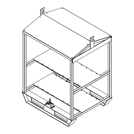
Page 14: Installing Welding Power Source Onto Rack
2-3. Installing Welding Power Source Onto Rack ST-801 192 / ST-801 696 / ST-801 698 Welding Power Source Securing Bolts And Hardware Install supplied bolts through rack shelf into welding power source Position welding power source onto rack shelf so threaded holes in feet and tighten. -
Page 15: Selecting Cable Sizes
2-5. Selecting Cable Sizes Y ARC WELDING can cause Electromagnetic Interference. To reduce possible interference, keep weld cables as short as possible, close together, and down low, such as on the floor. Locate welding operation 100 meters from any sensitive electronic equipment. Be sure this welding machine is installed and grounded according to this manual. -
Page 16: Common Work Connections
2-6. Common Work Connections ST-801 700 Y Turn Off welding power sources by Y INADEQUATE WORK CABLE CON- reach from negative (−) output receptacle to placing Power circuit breakers in the NECTIONS can cause serious dam- isolated terminal. Off position before making any weld age to input power service and create Common Negative (−) Weld Output output connections. -
Page 17: Paralleling Welding Power Sources For Smaw
2-7. Paralleling Welding Power Sources For SMAW Securely cover connection with proper insulating material. ST-801 701 Y Turn Off welding power sources by position of the welding cable connec- Determine cable sizes according to welding placing Power circuit breakers in the tors while welding. -
Page 18: Connecting Input Power To Rack
2-8. Connecting Input Power To Rack Have only qualified persons make this installation. Y Turn Off welding power sources before inspecting or installing rack. Control Box Open access door. Line Disconnect Device Of Proper Rating Input Conductors Grounding Conductor Select size and length using Sec- tion 2-9 or 2-10. -
Page 19: Electrical Service Guide For 4-Racks
2-9. Electrical Service Guide For 4-Racks Input Voltage Max Recommended Standard Fuse Or Circuit Breaker Rating In Amperes Min Input Conductor Size In AWG/Kcmil Max Recommended Input Conductor Length In Feet (Meters) 210 (64) 301 (92) 300 (91) Min Grounding Conductor Size In AWG/Kcmil Reference: 1996 National Electrical Code (NEC). -
Page 20: Overload Protection
3-2. Overload Protection Control Box Power Circuit Breaker (230/460 Volt Models); Location Of 3-Phase Fuse Block (460/575 Volt Models) Each Power circuit breaker or fuse block protects the welding power source connected to it from overload. In 230/460 volt models, if a Power circuit breaker opens, the matching welding power source shuts down. -
Page 21: Section 4 − Electrical Diagrams
SECTION 4 − ELECTRICAL DIAGRAMS SA-184 000 Figure 4-1. Circuit Diagram For 4-Rack Control Panel (230/460 Volt Model) SA-184 138 Figure 4-2. Circuit Diagram For 6-Rack Control Panel (230/460 Volt Model) OM-818 Page 17... - Page 22 SA-184 139 Figure 4-3. Circuit Diagram For 4-Rack Control Panel (460/575 Volt Model) SA-184 140 Figure 4-4. Circuit Diagram For 6-Rack Control Panel (460/575 Volt Model) OM-818 Page 18...
- Page 23 Notes OM-818 Page 19...
- Page 24 Notes OM-818 Page 20...
- Page 25 Notes OM-818 Page 21...
- Page 26 Notes OM-818 Page 22...
Need help?
Do you have a question about the XMT 304 and is the answer not in the manual?
Questions and answers