Cc/dc welding power source for gtaw, gtaw-p and smaw welding (33 pages)
Summary of Contents for Miller XRW
Page 1
OM-1581 137 532AH 2015−04 Processes MIG (GMAW) Welding Description 
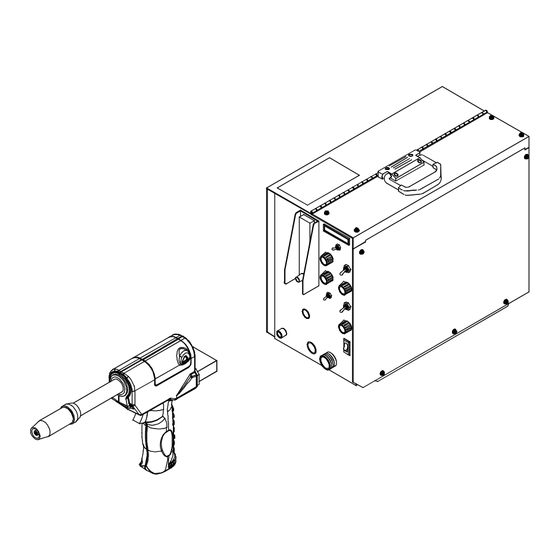
Wire Feeder And Feeder Gun ™ ™ XR A And XR W File: MIG (GMAW) Visit our website at www.MillerWelds.com...
Page 2
We know you don’t have time to do it any other way. That’s why when Niels Miller first started building arc welders in 1929, he made sure his products offered long-lasting value and superior quality.
SECTION 1 − SAFETY PRECAUTIONS - READ BEFORE USING som 2013−09 Protect yourself and others from injury — read, follow, and save these important safety precautions and operating instructions. 1-1. Symbol Usage DANGER! − Indicates a hazardous situation which, if Indicates special instructions.
Page 6
D Remove stick electrode from holder or cut off welding wire at FUMES AND GASES can be hazardous. contact tip when not in use. D Wear body protection made from durable, flame−resistant material Welding produces fumes and gases. Breathing (leather, heavy cotton, wool). Body protection includes oil-free these fumes and gases can be hazardous to your clothing such as leather gloves, heavy shirt, cuffless trousers, high health.
1-3. Additional Symbols For Installation, Operation, And Maintenance FIRE OR EXPLOSION hazard. MOVING PARTS can injure. D Do not install or place unit on, over, or near D Keep away from moving parts such as fans. combustible surfaces. D Keep all doors, panels, covers, and guards D Do not install unit near flammables.
1-4. California Proposition 65 Warnings Welding or cutting equipment produces fumes or gases This product contains chemicals, including lead, known to which contain chemicals known to the State of California to the state of California to cause cancer, birth defects, or other cause birth defects and, in some cases, cancer.
SECTION 2 − CONSIGNES DE SÉCURITÉ − LIRE AVANT UTILISATION fre_som_2013−09 Pour écarter les risques de blessure pour vous−même et pour autrui — lire, appliquer et ranger en lieu sûr ces consignes relatives aux précautions de sécurité et au mode opératoire. 2-1.
Page 10
D Ne pas raccorder plus d’une électrode ou plus d’un câble de D Avoir recours à des écrans protecteurs ou à des rideaux pour masse à une même borne de sortie de soudage. Débrancher le protéger les autres contre les rayonnements les éblouissements câble pour le procédé...
DES PIECES DE METAL ou DES LES BOUTEILLES peuvent exploser si elles sont endommagées. SALETES peuvent provoquer des blessures dans les yeux. Les bouteilles de gaz comprimé contiennent du gaz sous haute pression. Si une bouteille est D Le soudage, l’écaillement, le passage de la endommagée, elle peut exploser.
Page 12
LES CHARGES ÉLECTROSTATI- RAYONNEMENT HAUTE QUES peuvent endommager les cir- FRÉQUENCE (H.F.) risque cuits imprimés. provoquer des interférences. D Établir la connexion avec la barrette de terre D Le rayonnement haute fréquence (H.F.) peut avant de manipuler des cartes ou des pièces. provoquer des interférences avec les équi- D Utiliser des pochettes et des boîtes antista- pements de radio−navigation et de com-...
2-4. Proposition californienne 65 Avertissements Les équipements de soudage et de coupage produisent des Ce produit contient des produits chimiques, notamment du fumées et des gaz qui contiennent des produits chimiques plomb, dont l’État de Californie reconnaît qu’ils provoquent dont l’État de Californie reconnaît qu’ils provoquent des mal- des cancers, des malformations congénitales ou d’autres formations congénitales et, dans certains cas, des cancers.
SECTION 3 − DEFINITIONS 3-1. Additional Safety Symbols And Definitions Some symbols are found only on CE products. Warning! Watch Out! There are possible hazards as shown by the symbols. Safe1 2012−05 3-2. Miscellaneous Symbols And Definitions Some symbols are found only on CE products. Amperes Trigger Rated Current...
SECTION 4 − SPECIFICATIONS 4-1. Wire Feeder Specifications Specification Description Type Of Input Power 115 Volts AC, 3 Amperes At 50/60 Or 100 Hz Power Control Circuit Voltage Provided At Gun 30 Volts DC Wire Feed Speed Range 70-875 ipm (1.9-22.2 mpm) Overall Dimensions Length: 19 in.
SECTION 5 − INSTALLATION Be sure that contact tip, liner, and drive rolls are correct for wire size and type. See Section 5 to change parts as needed. See Section 7 for list of other available contact tips. Review Section 5-1 through Section 5-4 to determine how equipment will be connected. Air-cooled models are shown in Section 5-1 through Section 5-4.
5-2. Connections With A CV Welding Power Source Having Separate 115 VAC And Contactor Control Receptacles Constant Voltage (CV) Weld- ing Power Source Plug Obtain matching plugs for connect- ing to power source receptacles. Workpiece Voltage Sensing Lead Do not connect to workpiece. Wire Feeder 115 VAC/Contactor Control Cord...
5-4. Connections With A CC Welding Power Source And A 115 VAC/12 VDC Secondary Contactor Constant Current (CC) Weld- ing Power Source Workpiece Voltage Sensing Lead Wire Feeder 3-Conductor 115 VAC Cord 3-Conductor Contactor Con- trol Cord 5-Pin Plug Secondary Contactor 10 Gas Cylinder 11 115 VAC Plug Obtain plug for wire feeder.
5-6. Air-Cooled Gun Connections Gun Control Cable Insert plug into Gun Control recep- tacle, and tighten threaded collar. Gas Hose Connect to Gas fitting on feeder. Weld Cable Weld Cable Terminal In Feeder Connect gun weld cable to weld cable terminal in feeder. Wire Conduit Thumbscrew Wire Conduit Block...
5-7. Water-Cooled Gun Connections Gas Hose Connect to Gas fitting on feeder. Water Hose Connect to water to gun fitting on feeder (left-hand threads). Wire Conduit Thumbscrew Wire Conduit Block Loosen thumbscrew, and insert conduit through Wire opening until it bottoms against block. Trim liner if necessary, as close to the rolls as possible.
5-8. Air-Cooled Feeder Connections Gas Hose Grommet 10 ft (3 m) Gas Hose Rear Of Gas Fitting Route one end of gas hose through grommet, and connect hose to rear of Gas fitting in feeder. Connect remaining hose regulator/flowmeter . Weld Cable To Welding Power Source Select and prepare weld cable ac-...
5-9. Water-Cooled Feeder Connections Obtain coolant supply. Gas Hose Grommet 10 ft (3 m) Gas Hose Rear Of Gas Fitting Route one end of gas hose through grommet, and connect hose to rear of Gas fitting in feeder. Connect remaining hose regulator/flowmeter .
5-10. Voltage Sensing Lead Connections Unit is factory set for constant volt- age (CV) welding. To set unit for constant current (CC) welding, proceed as follows: Terminal Strip 2T Strain Relief Loosen screws of strain relief. Voltage Sensing Lead Route ring terminal end of lead through strain relief, and connect ring terminal to terminal A of terminal strip 2T.
5-11. 115 VAC/Contactor Control Plug Information Interconnecting Cord 115 VAC/Contactor Control Plug PLG5 If CC or CC/CV welding power source is equipped with matching 14-socket receptacle, insert plug, tighten threaded collar. Proceed to Section 5-13. If plug PLG5 will not connect to CC welding power source receptacle, use the following pin information and Section 5-12 to replace PLG5...
5-12. Replacing 115 VAC/Contactor Control Plug With Customer-Supplied 5-Pin Or Twistlock Plug 115 VAC/Contactor Control Plug PLG5 Contactor Control Cord 115 VAC Cord Find and label cords by following leads to back of PLG5: Contactor control cord connects to pins A & B of PLG5 115 VAC cord connects to pin J of PLG5.
5-13. Installing Wire Spool Turn Off wire feeder and welding power source. Wire Spool Top Cover Pressure Roll Assembly Gun Contact Tip If wire spool is being replaced, open pressure roll assembly in gun, and cut welding wire off at contact tip. For welding power sources without contactor, retract wire onto spool.
5-14. Threading Welding Wire Through Feeder Wire Spool Loosen wire from spool, cut off bent wire, and pull 6 in (150 mm) of wire off spool. Tension Arm Mounting Arm To open pressure roll assembly, open tension arm and lift mounting arm.
5-15. Threading Welding Wire Through Gun Pressure Roll Assembly Lift arm and open pressure roll assembly. Wire Conduit Lay wire conduit out straight. Jog Switch Push Jog switch up to feed wire through wire conduit. Drive Roll For wire sizes .035 in. (0.9 mm) and smaller use small groove, and .047 in.
5-17. Adjusting Wire Feed Starting Speed To adjust wire feed starting speed, proceed as follows: Turn Off wire feeder and welding power source. Open right side panel. Motor Speed Control Board Motor Start Control Potentiometer R70 Turn potentiometer clockwise to increase time it takes the motor to ramp up to speed.
SECTION 6 − OPERATION 6-1. Front Panel Controls Of Feeder (Air-Cooled Model Shown) Voltage/Wire Speed Meter (Optional) Voltage/Wire Speed Switch (Optional) Run-In Speed Control Jog Switch Burnback Time Control (Optional) Spot/Continuous Switch (Optional) Remote Voltage Control (Optional) Power Switch Time Range Switch (Optional) 10 Spot Time Control (Optional) 11 Flowmeter (Optional) 151 780−A...
6-4. Run-In Speed Control Run-In Speed Control Use control to set wire feed speed before arc initiation. After arc initiation, wire feed speed is controlled by the Wire Speed Control on the welding gun (see Section 6-12). The scale around the control is per- cent of full range, not wire speed.
6-7. Spot Controls (Optional) Spot/Continuous Switch Use switch to select either an un- timed continuous weld cycle or a timed spot weld cycle. Both weld cycles consist of the following steps: run-in, weld (untimed or spot time), and burnback. Time Range Switch Use switch to select spot weld time range.
6-10. Flowmeter (Optional) NOTICE − Wire feeding system is designed for maximum of 50 psi (345 kPa) gas pressure. Be sure that regulator/flowme- ter has preset conditions of no more than 50 psi (345 kPa) gas pressure. Flowmeter Valve Use flowmeter to control shielding gas flow at the feeder.
6-12. Gun Controls Gun Trigger Press trigger to energize welding power source contactor (if applica- ble), start shielding gas flow, and begin wire feed. For shielding gas preflow and post- flow, partially press trigger before and partially release after welding. Wire Speed Control Use control to adjust wire feed speed.
SECTION 7 − MAINTENANCE & TROUBLESHOOTING Maintain more often Disconnect power before maintaining. during severe conditions. n = Check Z = Change ~ = Clean l = Replace * To be done by Factory Authorized Service Agent Daily n Check barrel clamp l Repair Or Replace screws for tightness.
7-1. Changing Or Cleaning Gun Drive Roll Turn Off wire feeder and welding power source. Top Cover Pressure Roll Assembly Cut off wire where it enters pressure roll assembly area. Setscrew Current Pick-Up Tab This tab helps prevent burnback caused by welding arcs inside the contact tip.
7-2. Changing Feeder Drive Roll And Wire Inlet Guide Turn Off wire feeder and welding power source. Lay wire conduit out straight. Open gun pressure roll assembly, and cut welding wire off at contact tip. Pressure Roll Assembly Wire Spool For welding power sources without contactor, retract wire onto spool.
7-3. Replacing Or Cleaning Gun Drive Roll Bearing Turn Off wire feeder and welding power source. Top Cover Pressure Roll Assembly Screw Pressure Roll Remove as shown. Use a wire brush to clean bearing. Reinstall with washers, and tighten screw. Close pressure roll assembly.
7-5. Changing Gun Contact Tip Remove nozzle Nozzle FasTip Unscrew FasTip. Install new FasTip. Ref. 150 437-A 7-6. Removing Diffuser In Air And Water-Cooled Pistol-Grip Guns Turn Off welding power source and water supply be- fore working on gun. Stop engine on welding genera- tors.
7-7. Replacing The Liner Turn Off wire feeder and welding power source. Drive Roll Collet Nut Lay gun cable out straight. Remove drive roll on gun and collet nut on on both ends of liner tube assembly and remove old liner. New Liner Insert split end of new liner into liner tube assembly and continue feed-...
7-8. Replacing Hub Assembly Turn Off wire feeder and welding power source. Remove gun top cover and open pressure roll assembly as shown in Section 7-3. Retract wire onto spool and remove spool. Take hub apart as shown. Metal Brake Washer Flat Washer Brake Washer Keyed Washer...
7-9. Adjusting Hub Tension Turn On welding power source and wire feeder make this adjustment. Wire Speed Control Adjust control to wire speed for welding. Jog Switch Push up, and then release Jog switch. Hub tension is okay if wire unwinds freely, but wire does not backlash when Jog switch is released.
7-12. Troubleshooting A. Wire Feeder Trouble Trouble Remedy Pressing gun trigger does not energize Secure plug from gun control cable into Gun Control receptacle on feeder (see Section 5-6). feeder. Welding wire is not energized. Shielding gas flows. Secure 115 VAC input plug connection (see Section 5-11). Check fuse F1 (see Section 7-10).
Page 45
B. Gun Trouble Trouble Remedy No weld output; gun/feeder does not Secure 115 VAC input plug in 115 volts AC receptacle (see Section 5-11). work. Place Power switch on welding power source in the On position. Erratic weld output. Tighten and clean all connections. Pressing gun/feeder trigger does not en- Secure plug from gun control cable into 10-socket receptacle on wire feeder (see Section 5-6).
SECTION 9 − PARTS LIST Hardware is common and not available unless listed. This main assembly drawing shows the XR-W (water-cooled model). Some parts for the XR-A (air-cooled model) vary in appearance. When differences occur, they are called out in the part description.
Page 49
Item Dia. Part Mkgs. Description Quantity Figure 9-1. Main Assembly ....089572 Catch, Link-lock ..........
Page 50
Item Dia. Part Mkgs. Description Quantity Figure 9-1. Main Assembly (Continued) ....111152 Skid, Base ............
Page 52
Hardware is common and not available unless listed. See Fig 9-1 Item 59 145 127-B Figure 9-3. Panel, Front w/Components (Water-Cooled Model Illustrated) OM-1581 Page 48...
Page 56
Item Dia. Part Mkgs. Description Quantity Figure 9-4. Exploded View Of Gun (Continued) ... . . 231531 Head Tube Assy, (Air Cooled) (See Figure 9-5) ......
Page 57
Hardware is common and not available unless listed. Ref. 800 434-G Figure 9-5. Head Tube Assembly Of Pistol-Grip Gun Item Part Description Quantity Figure 9-5. Head Tube Assembly Of Pistol-Grip Gun (Figure 9-4 Item 24) ....199613 Nozzle, Brass 5/8 In Orifice Tapered .
SECTION 10 − PARTS LIST INCLUDING CONSUMABLES Item Number .030−1/16” WIRE STANDARD INSULATOR .030−1/16” WIRE .035−1/16” WIRE COLLARED (231 512) .030−1/16” WIRE XR-A Spoolmatic INSULATOR Barrel Assy (227 749) (#232 284) 6.0” STRAIGHT (#221 087) XR-W Barrel Assy (231 511) 6.0”...
Page 59
Item Part Description Quantity Figure 10-1. Consumables Flowchart Table 10-1. Nozzles ♦176238 ... . Nozzle, Spot Flat (Requires Diffuser 209099, Used With Any Heavy Duty FasTipt Contact Tip) ........♦176240 .
Page 60
Item Part Description Quantity Figure 10-1. Consumables Flowchart (Continued) Table 10-5. Value Multi−Turn Contact Tips* ♦071825 ... . .030 in (0.9 mm) ........... . ♦054202 .
Page 61
Notes Start Your Professional Over 80,000 trained 400 Trade Square East, Troy, Ohio 45373 Welding Career Now! since 1930! 1-800-332-9448 www.welding.org...
Page 63
Effective January 1, 2015 (Equipment with a serial number preface of MF or newer) This limited warranty supersedes all previous Miller warranties and is exclusive with no other guarantees or warranties expressed or implied. Warranty Questions? LIMITED WARRANTY − Subject to the terms and conditions below, 6 Months —...
Need help?
Do you have a question about the XRW and is the answer not in the manual?
Questions and answers