Miller Spectrum 375 Owner's Manual
Hide thumbs
Also See for Spectrum 375:
- Owner's manual (44 pages) ,
- Owner's manual (40 pages) ,
- Owner's manual (36 pages)

Related Manuals for Miller Spectrum 375


Summary of Contents for Miller Spectrum 375
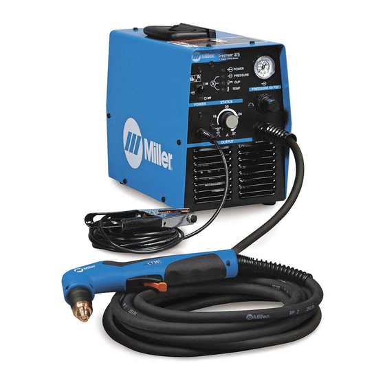
- Page 1 OM-255 590A 2011−12 Processes Air Plasma Cutting and Gouging Description Air Plasma Cutter Spectrum 375 And XT30C Torch File: Plasma Cutters Visit our website at www.MillerWelds.com...
- Page 2 We know you don’t have time to do it any other way. That’s why when Niels Miller first started building arc welders in 1929, he made sure his products offered long-lasting value and superior quality.
-
Page 3: Table Of Contents
TABLE OF CONTENTS SECTION 1 − SAFETY PRECAUTIONS - READ BEFORE USING ........1-1. -
Page 5: Section 1 − Safety Precautions - Read Before Using
SECTION 1 − SAFETY PRECAUTIONS - READ BEFORE USING pom_2011-10 Protect yourself and others from injury — read, follow, and save these important safety precautions and operating instructions. 1-1. Symbol Usage DANGER! − Indicates a hazardous situation which, if Indicates special instructions. not avoided, will result in death or serious injury. -
Page 6: Electric Shock Can Kill
FUMES AND GASES can be hazardous ELECTRIC SHOCK can kill. SIGNIFICANT DC VOLTAGE exists in Cutting produces fumes and gases. Breathing inverter power sources AFTER the re- these fumes and gases can be hazardous to your health. moval of input power. Keep your head out of the fumes. -
Page 7: Additional Symbols For Installation, Operation, And Maintenance
1-3. Additional Symbols For Installation, Operation, And Maintenance HOT PARTS can burn. FALLING EQUIPMENT can injure. D Do not touch hot parts bare handed. D Use lifting eye to lift unit only, NOT running gear, gas cylinders, or any other accessories. D Allow cooling period before working on equipment. -
Page 8: California Proposition 65 Warnings
1-4. California Proposition 65 Warnings Welding or cutting equipment produces fumes or gases This product contains chemicals, including lead, known to which contain chemicals known to the State of California to the state of California to cause cancer, birth defects, or other cause birth defects and, in some cases, cancer. -
Page 9: Section 2 − Consignes De Sécurité − Lire Avant Utilisation
SECTION 2 − CONSIGNES DE SÉCURITÉ − LIRE AVANT UTILISATION pom_2011−10fre Pour écarter les risques de blessure pour vous−même et pour autrui — lire, appliquer et ranger en lieu sûr ces consignes relatives aux précautions de sécurité et au mode opératoire. 2-1. - Page 10 D Coupez l’alimentation d’entrée avant d’installer l’appareil ou d’ef- ÉTINCELLES PROJETÉES fectuer l’entretien. Verrouillez ou étiquetez la sortie d’alimentation peuvent provoquer des blessures. selon la norme OSHA 29 CFR 1910.147 (reportez−vous aux Prin- cipales normes de sécurité). Le coupage plasma produit des étincelles et projec- tions de métal à...
-
Page 11: Dangers Supplémentaires En Relation Avec L'installation, Le Fonctionnement Et La Maintenance
D Si vous êtes à l’intérieur au moment du coupage, ventilez la pièce D Ne pointez pas le chalumeau en direction de votre corps ni de la ou ayez recours à une ventilation aspirante installée près de l’arc pièce à couper lorsque vous appuyez sur la gâchette − l’arc pilote pour évacuer les vapeurs et les gaz. - Page 12 Risque D’INCENDIE OU LIRE LES INSTRUCTIONS. D’EXPLOSION. D Lire et appliquer les instructions sur les étiquettes et le Mode d’emploi avant l’instal- D Ne pas placer l’appareil sur, au-dessus ou à lation, l’utilisation ou l’entretien de l’appareil. proximité de surfaces infllammables. Lire les informations de sécurité...
-
Page 13: Proposition Californienne 65 Avertissements
2-4. Proposition californienne 65 Avertissements Les équipements de soudage et de coupage produisent des Ce produit contient des éléments chimiques, dont le plomb, fumées et des gaz qui contiennent des produits chimiques reconnus par l’État de Californie pour leur caractère dont l’État de Californie reconnaît qu’ils provoquent des mal- cancérogène ainsi que provoquant des malformations formations congénitales et, dans certains cas, des cancers. -
Page 14: Section 3 − Definitions
A complete Parts List is available at www.MillerWelds.com SECTION 3 − DEFINITIONS 3-1. Symbols And Definitions For Nameplate And Serial Number/Rating Label Plasma Arc Cutting Adjust Air/Gas Low Air Pressure Amperes (PAC) Pressure Light No − Do Not Do Volts Increase Temperature This... -
Page 15: Section 4 − Installation
A complete Parts List is available at www.MillerWelds.com SECTION 4 − INSTALLATION 4-1. Unit Specifications Power Supply Input −− Rated AC Phase and line frequency (Hz) 1 − Phase 60 Hz Rated Input Voltage (U ) and rated Input Current (I and I eff at rated output. - Page 16 Toppling or tilting Up to 15° incline Torch − The XT30C torch is intended for handheld use only. The torch conforms to IEC 60974-7 when used with the Spectrum 375. Do not use this torch in combination with any other machines. −−...
-
Page 17: Duty Cycle And Overheating
A complete Parts List is available at www.MillerWelds.com 4-2. Duty Cycle And Overheating For Units Connected to a 115 Volt Circuit Duty Cycle is percentage of 10 min- or a 230 Volt Circuit: utes that unit can cut at rated load without overheating. -
Page 18: Serial Number And Rating Label Location
A complete Parts List is available at www.MillerWelds.com 4-4. Serial Number And Rating Label Location The serial number and rating information for this product is located on the back. Use rating label to determine input power requirements and/or rated output. For future reference, write serial number in space provided on back cover of this manual. 4-5. -
Page 19: Connecting Gas/Air Supply
A complete Parts List is available at www.MillerWelds.com 4-6. Connecting Gas/Air Supply Use only clean, dry air with 90 to 120 psi (621 to 827 kPa) pressure. Gas/Air Inlet Opening Hose Teflon Tape Obtain hose with 1/4 NPT right- hand thread fitting. Wrap threads Tools Needed: with teflon tape (optional) or apply pipe sealant, and install fitting in... -
Page 20: Electrical Service Guide
A complete Parts List is available at www.MillerWelds.com 4-8. Electrical Service Guide Failure to follow these electrical service guide recommendations could create an electric shock or fire hazard. These recommenda- tions are for a dedicated branch circuit sized for the rated output and duty cycle of the welding power source. NOTICE −... -
Page 21: Installing Alternative Plug
A complete Parts List is available at www.MillerWelds.com 4-11. Installing Alternative Plug Supplied 115 VAC Plug Cut cord close to plug. Alternative Plug (230 VAC Plug Shown) This procedure is necessary if the unit is to be connected to a 230 VAC receptacle, Load 1 (Brass) Terminal or to a 115 VAC receptacle that requires a plug that is different from the supplied plug. -
Page 22: Section 5 − Operation
A complete Parts List is available at www.MillerWelds.com SECTION 5 − OPERATION 5-1. Controls PRESSURE 60 PSI Set To 60 PSI (414 kPa) Setting Gas/Air Pressure Requires 90-120 PSI (621-827 kPa) Supply Output Control put and/or the cut time or find more adequate Place Output control in Gas/Air position and power (see Section 4-1). -
Page 23: Cutting Speed
A complete Parts List is available at www.MillerWelds.com 5-2. Cutting Speed Recommended Cut Speeds At 27 Amperes Output Thickness Recommended Cut Speeds* Inches mm/min 1,778 Mild Steel 3/16 1,194 12.7 *Recommended Cut Speed is approximately 80% of maximum. Aluminum and Stainless Steel cut speeds at these thicknesses may be reduced as much as 20%. Recommended Cut Speeds At 20 Amperes Output Thickness Recommended Cut Speeds*... -
Page 24: Plasma Cutting System Practices
A complete Parts List is available at www.MillerWelds.com 5-4. Plasma Cutting System Practices The pilot arc starts immediately when trigger is pressed. Always connect work clamp to a clean, DO NOT start pilot arc without cutting or paint-free location on workpiece, as close to gouging as this shortens the service life cutting area as possible. -
Page 25: Sequence Of Cutting Operation
A complete Parts List is available at www.MillerWelds.com 5-5. Sequence Of Cutting Operation ° Connect work clamp to a clean, paint-free For standard (shielded) cutting, place drag shield on edge location on workpiece, as close to cutting of metal. For extended (non-shielded) cutting, use 1/8 in. area as possible. -
Page 26: Sequence Of Piercing Operation
A complete Parts List is available at www.MillerWelds.com 5-6. Sequence Of Piercing Operation The pilot arc starts immediately when trigger is pressed. ° Connect work clamp to a clean, paint-free Hold torch at approximately 45° location on workpiece, as close to cutting to the workpiece. -
Page 27: Section 6 − Maintenance & Troubleshooting
A complete Parts List is available at www.MillerWelds.com SECTION 6 − MAINTENANCE & TROUBLESHOOTING 6-1. Routine Maintenance Disconnect power Maintain more often before maintaining. during severe conditions. n = Check Z = Change ~ = Clean l = Replace Reference * To be done by Factory Authorized Service Agent Each Section 4-6,... -
Page 28: Overload Protection: Trouble Lights & Checking Shield Cup Shutdown System
A complete Parts List is available at www.MillerWelds.com 6-2. Overload Protection: Trouble Lights & Checking Shield Cup Shutdown System Power Light Light is steady if input power is okay. Light flashes for the following conditions: If input power is 115 volts AC, but power supply is less than 92 volts AC or greater than 138 volts AC. -
Page 29: Torch And Work Cable Connections
A complete Parts List is available at www.MillerWelds.com 6-3. Torch And Work Cable Connections If torch or work cable needs to be removed or replaced, proceed as follows: Turn power Off, and disconnect input power plug from receptacle. Remove wrapper from unit. Torch Connections Remove existing torch cable from unit. -
Page 30: Checking/Replacing Retaining Cup, Tip, And Electrode
A complete Parts List is available at www.MillerWelds.com 6-4. Checking/Replacing Retaining Cup, Tip, And Electrode Overtightening will strip threads. Do not overtighten retaining cup during assembly. Do not cross-thread parts causing stripping. Use care during torch assembly and parts replacement. Inspect shield cup, tip, and electrode for wear before cutting or whenever cutting speed has been signifi- cantly reduced. -
Page 31: Troubleshooting Power Source
A complete Parts List is available at www.MillerWelds.com 6-5. Troubleshooting Power Source Is input power Check torch consumables. Is Cup Status Connect unit to proper input connected to Reset Power switch S1. light On or voltage (see Section 4-10). correct line flashing? voltage? -
Page 32: Troubleshooting Torch
A complete Parts List is available at www.MillerWelds.com 6-6. Troubleshooting Torch Torch travel speed too slow; increase travel speed (see Section 5-2). Clean Does arc go replace torch consumables Go to Section 6-5. as necessary (see Section while cutting? 6-4). Be sure work clamp is securely attached workpiece. -
Page 33: Section 7 − Electrical Diagram
SECTION 7 − ELECTRICAL DIAGRAM 256 065-A Figure 7-1. Circuit Diagram OM-255 590 Page 29... -
Page 34: Section 8 − Parts List
SECTION 8 − PARTS LIST 8-1. Recommended Spare Parts Item Dia. Part Mkgs. Description Quantity Recommended Spare Parts ....227877 Element, Filter Air ........... . - Page 35 Item Part Description 249 970 Torch Handle Kit (1) 249 971 Torch Trigger ....Microswitch (1) 255 686 Leads, 20 ft (1) 252 938 Torch Body Kit (1) 249 972 Torch Trigger Assembly w/Spring (1)
- Page 36 Notes Work like a Pro! Pros weld and cut safely. Read the safety rules at the beginning of this manual.
- Page 37 Notes MATERIAL THICKNESS REFERENCE CHART 24 Gauge (.025 in.) 22 Gauge (.031 in.) 20 Gauge (.037 in.) 18 Gauge (.050 in.) 16 Gauge (.063 in.) 14 Gauge (.078 in.) 1/8 in. (.125 in.) 3/16 in. (.188 in.) 1/4 in. (.25 in.) 5/16 in.
- Page 38 Notes...
- Page 39 Effective January 1, 2011 (Equipment with a serial number preface of MB or newer) This limited warranty supersedes all previous Miller warranties and is exclusive with no other Warranty Questions? guarantees or warranties expressed or implied. LIMITED WARRANTY − Subject to the terms and conditions 90 Days —...
- Page 40 Contact the Delivering Carrier to: File a claim for loss or damage during shipment. For assistance in filing or settling claims, contact your distributor and/or equipment manufacturer’s Transportation Department. © ORIGINAL INSTRUCTIONS − PRINTED IN USA 2011 Miller Electric Mfg. Co. 2011−01...
Need help?
Do you have a question about the Spectrum 375 and is the answer not in the manual?
Questions and answers