Table of Contents
Advertisement
For product information,
Owner's Manual translations,
and more, visit
www.MillerWelds.com
™
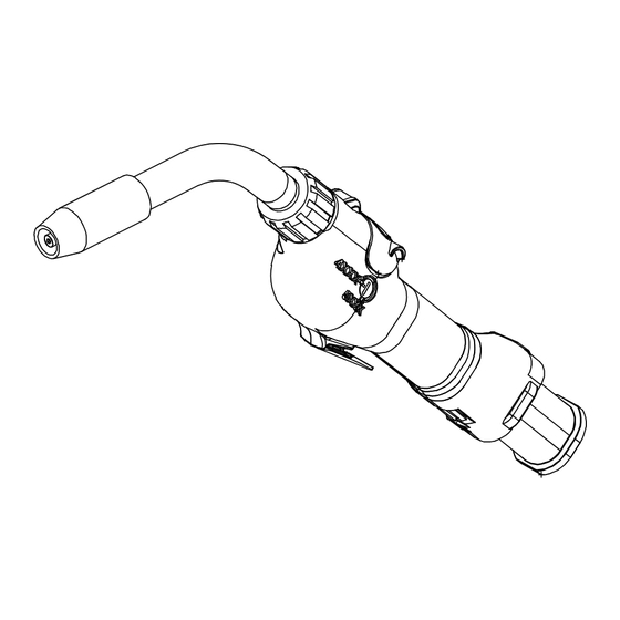
XR - AlumaPro
(Air And Water-Cooled Guns)
CE And Non-CE Models
300 Ampere (Air) Push-Pull Welding Gun
400 Ampere (Water) Push-Pull Welding Gun
OM-227398S
2019−05
Processes
MIG (GMAW) Welding
Description
Semi-Automatic, Air/Water-
Cooled, MIG (GMAW) Welding
Gun
File: MIG (GMAW)
Advertisement
Table of Contents
Troubleshooting

Related Manuals for Miller XR-AlumaPro Series


Summary of Contents for Miller XR-AlumaPro Series
- Page 1 OM-227398S 2019−05 Processes MIG (GMAW) Welding Description Semi-Automatic, Air/Water- Cooled, MIG (GMAW) Welding ™ XR - AlumaPro (Air And Water-Cooled Guns) CE And Non-CE Models 300 Ampere (Air) Push-Pull Welding Gun 400 Ampere (Water) Push-Pull Welding Gun File: MIG (GMAW) For product information, Owner’s Manual translations, and more, visit...
- Page 2 We know you don’t have time to do it any other way. That’s why when Niels Miller first started building arc welders in 1929, he made sure his products offered long-lasting value and superior quality.
-
Page 3: Table Of Contents
TABLE OF CONTENTS SECTION 1 −SAFETY PRECAUTIONS FOR GMAW WELDING GUNS − READ BEFORE USING ..1-1. Symbol Usage ............... . 1-2. - Page 4 DECLARATION OF CONFORMITY for European Community (CE marked) products. MILLER Electric Mfg. Co., 1635 Spencer Street, Appleton, WI 54914 U.S.A. declares that the product(s) identified in this declaration conform to the essential requirements and provisions of the stated Council Directive(s) and Standard(s).
-
Page 5: Section 1 −Safety Precautions For Gmaw Welding Guns − Read Before Using
SECTION 1 −SAFETY PRECAUTIONS FOR GMAW WELDING GUNS − READ BEFORE USING SR7 (MIG) 2018-01 Protect yourself and others from injury — read, follow, and save these important safety precautions and operating instructions. 1-1. Symbol Usage DANGER! − Indicates a hazardous situation which, if Indicates special instructions. -
Page 6: Proposition 65 Warnings
NOISE can damage hearing. READ INSTRUCTIONS. D Read and follow all labels and the Owner’s Noise from some processes or equipment can damage hearing. Manual carefully before installing, operating, or servicing unit. Read the safety information at D Check for noise level limits exceeding those the beginning of the manual and in each specified by OSHA. -
Page 7: Utilisation
SECTION 2 − MESURES DE SÉCURITÉ VISANT LES PISTOLETS DE SOUDAGE GMAW − À LIRE AVANT UTILISATION SR7(MIG)_2018−01_fre Pour écarter les risques de blessure pour vous−même et pour autrui — lire, appliquer et ranger en lieu sûr ces consignes relatives aux précautions de sécurité... -
Page 8: Proposition Californienne 65 Avertissements
D Avoir recours à des écrans protecteurs ou à des rideaux pour D Utiliser des bouche-oreilles ou des serre-tête antibruit approuvés si protéger les autres contre les rayonnements les éblouissements le niveau de bruit est élevé. et les étincelles ; prévenir toute personne sur les lieux de ne pas D Avertir les personnes à... -
Page 9: Section 3 − Definitions
SECTION 3 − DEFINITIONS 3-1. Additional Safety Symbols And Definitions Some symbols are found only on CE products. Warning! Watch Out! There are possible hazards as shown by the symbols. Safe1 2012−05 Do not discard product (where applicable) with general waste. Reuse or recycle Waste Electrical and Electronic Equipment (WEEE) by disposing at a designated collection facility. -
Page 10: Section 4 − Specifications
SECTION 4 − SPECIFICATIONS 4-1. Specifications Model Welding Output Range Electrode Wire Feed Net Weight Wire Diameter Speed Range (Torch Only) Capacity XR-A AlumaPro 15 ft (4.7 m) 300 A at 100% Duty Cycle .030 To 1/16 in. 70 To 900 ipm 2.5 lb (1.1 kg) XR-A AlumaPro 25 ft (7.6 m) (0.8 To 1.6 mm) -
Page 11: Duty Cycle And Overheating
4-3. Duty Cycle And Overheating Duty Cycle is percentage of 10 min- utes that unit can weld at rated load without overheating. NOTICE − Exceeding duty cycle can damage unit and void warranty. Air-Cooled Models 100% Duty Cycle At 300 Peak Amperage Using 100% Argon Gas w/15, 25 Or 35 Foot Guns Continuous Welding Water-Cooled Models (CE) 100% Duty Cycle At 400 Peak Amperage Using 100% Argon Gas w/15, 25 Or 35 Foot Guns... -
Page 12: Section 5 − Installation
SECTION 5 − INSTALLATION Be sure that contact tip, liner, and drive rolls are correct for wire size and type. See Parts List to change parts as needed. 5-1. Connections With A Constant Current (CC), Constant Voltage (CV) Or Constant Current/Constant Voltage (CC/CV) Welding Power Source Having A 14-Socket Receptacle XR-D... -
Page 13: Air-Cooled Gun Connections
5-2. Air-Cooled Gun Connections Gun Control Cable Insert plug into Gun Control receptacle, and tighten threaded collar. Gun Power Pin Gun Bushing Gun Securing Knob Drive Casting Loosen gun securing knob and insert gun power pin through gun bushing until it bottoms against drive casting. -
Page 14: Water-Cooled Gun Connections
5-3. Water-Cooled Gun Connections Turn on coolant supply before welding or gun will be dam- aged. Gun Control Cable Insert plug into Gun Control receptacle, and tighten threaded collar. Gun Power Pin Gun Securing Knob Gun Bushing Drive Casting Loosen gun securing knob, and insert gun power pin through gun bushing until it bottoms against drive casting. -
Page 15: Millermatic 350P Water Cooled Gun Connections
5-4. Millermatic 350P Water Cooled Gun Connections Tools Needed: 9/16 in. Ref. 804945-A NOTICE − Turn on coolant supply before Water In Hose bottoms against block. Tighten knob. Close welding or gun will be damaged. and latch door. Connect to coolant supply with supplied Water Out Hose Coolant Supply coupler and water hose (left-hand threads). -
Page 16: Threading Welding Wire For Alumapro Gun And Millermatic 350P
5-5. Threading Welding Wire For AlumaPro Gun And Millermatic 350P Wire Spool Welding Wire Inlet Wire Guide Drive Roll Intermediate Wire Guide Outlet Wire Guide Pressure Adjustment Knob Gun Conduit Cable Lay gun cable out straight. Tools Needed: Hold wire tightly to keep it IMPORTANT! from unraveling. -
Page 17: Threading Welding Wire Through Xr-Control Feeder
5-6. Threading Welding Wire Through XR-Control Feeder Cable Assembly Lay cable assembly out straight. Jog Switch Tools Needed: Push Jog switch up to feed wire through cable assembly. Torque Switch Select proper push feeder torque set- ting for wire size being used. Use low torque for .030 in. -
Page 18: Adjusting Tension At Feeder
5-7. Adjusting Tension At Feeder Hold wire tightly to keep it from unraveling. 6 in. (150 mm) Pull and hold wire; cut off end. Tension Arm Open tension arm. Install proper size drive rolls. Thread wire thru inlet guide, along drive roll groove, and into wire conduit. -
Page 19: 10-Pin Plug Information
5-8. 10-Pin Plug Information Pin* Pin Information Electrode sense lead Motor Common Trigger Motor 0 to +24 volts DC with respect to pin B Trigger Wire speed Ref. +9 volts DC Wire speed com Wire speed 0 to +9 volts DC with respect to pin H Gun sensing resistor with respect to pin H Not used 5-9. -
Page 20: Threading Welding Wire Through Gun
5-10. Threading Welding Wire Through Gun Refer to Section 5-6 for instructions on feeding wire through feeder. For XR-AlumaPro Gun: JOG / PURGE Welding wire is electrically live when gun trigger is used to jog wire. Turn OFF coolant supply before threading wire Lay gun cable out straight. -
Page 21: Section 6 − Operation
SECTION 6 − OPERATION 6-1. Gun Controls Trigger Press trigger to energize welding power source contactor applicable), start shielding gas flow, and begin wire feed. Switches inside the wire feeder can be set to provide timed shielding gas preflow and postflow when trigger is pressed and released. -
Page 22: Shielding Gas
Maximum inlet pressure: 70 psi (483 kPa) Distilled Or Deionized Water OK ° ° Minimum cooling power: 1000 Watt (3410 BTU/hr) Above 32 F (0 Coolant ° ° *MILLER coolants protect to -37 F (-38 C) and resist algae growth. Ref. 150755-A OM-227398 Page 18... -
Page 23: Gun Drive Assembly Maintenance For An Xr-Alumapro Gun
6-5. Gun Drive Assembly Maintenance For An XR-AlumaPro Gun Lever Arm Using lever arm open pressure roll with bearing as shown. Retract wire onto spool. Drive Roll Use wire brush to clean drive roll. Install drive roll with hex opening down toward shaft hex, and secure with screw. -
Page 24: Replacing Head Tube Liner In Xr-Alumapro Guns
6-6. Replacing Head Tube Liner In XR-AlumaPro Guns Turn OFF coolant supply before removing head tube water-cooled gun. The standard head tube liner (yellow) will accommodate wire diameters from 3/64 in.- 1/16 in. wire size. When changing wire size, change control box drive roll, idler and head tube liner with appropriate sized lin- Head Tube... -
Page 25: Replacing The Gun Liner On Xr-Alumapro Guns
6-8. Replacing The Gun Liner On XR-AlumaPro Guns Gun End Refer To Instructions Below. Remove Old Liner (Item 2) From Gun End Install New Liner (Item 2) Into Gun End Power Pin End Gently pry open slots to remove wire collet guide. Cut liner flush with wire collet guide. -
Page 26: Section 7 − Maintenance & Troubleshooting
SECTION 7 − MAINTENANCE & TROUBLESHOOTING 7-1. Routine Maintenance For Aluminum Push/Pull Guns Disconnect power before maintaining. n = Check ~ = Clean l = Replace Daily n~ Head Tube Liner and Drive Casting (see Section 6-6) Weekly n~ Drive Roll Every Spool of Wire... -
Page 27: Cleaning The Gun Liner On Xr-Alumapro Guns
7-2. Cleaning The Gun Liner On XR-AlumaPro Guns Turn Off welding power source and wire feeder. NOTICE − Clean gun liner be- fore cleaning stainless tube and inlet guide. Lay gun cable out straight. Leather Cover Remove leather cover to ac- cess liner assembly. -
Page 28: Troubleshooting Table
7-3. Troubleshooting Table Disconnect power before troubleshooting. Trouble Remedy Reset circuit breaker in feeder/control box. See feeder/control owner’s manual. No wire feed at gun, feeder not operat- ing. Check motor or brake solenoid. Replace trigger-switch and test operation. Check trigger-switch wires for continuity. No wire feed at gun, feeder operating Reset circuit breaker in feeder/control box and check for short in motor leads. -
Page 29: Section 8 − Electrical Diagrams
SECTION 8 − ELECTRICAL DIAGRAMS 228669-B Figure 8-1. Circuit Diagram For XR-AlumaPro Gun Notes OM-227398 Page 25... -
Page 30: Section 9 − Parts List
SECTION 9 − PARTS LIST Hardware is common and not available unless listed. Figure 9-1. Exploded View Of XR-A AlumaPro Gun OM-227398 Page 26... - Page 31 T0047-A Item Part Description Quantity Figure 9-1. Exploded View Of XR-A AlumaPro Gun ... . . 231517 Kit, Head Tube Assy (Water) Long ........
- Page 32 Item Part Description Quantity Figure 9-1. Exploded View Of XR-A AlumaPro Gun (Continued) ... . . 227608 Reducer, Guide Liner ..........
- Page 33 Item Part Description Quantity Figure 9-1. Exploded View Of XR-A AlumaPro Gun (Continued) ... . . 227435 Arm, Pressure (Machined) ..........
- Page 34 To maintain the factory original performance of your equipment, use only Manufacturer’s Suggested Replacement Parts. Model and serial number required when ordering parts from your local distributor. Hardware is common and not available unless listed. 804705-A Figure 9-3. (Air) Head Tube Assembly Of AlumaPro Gun Item Part Description...
-
Page 35: Section 10 − Parts List Including Consumables
SECTION 10 − PARTS LIST INCLUDING CONSUMABLES Item Number XR-AlumaPro 4” Head Tube Inner Rear (#227 416) Air (Short) (#231 519) Outer XR-AlumaPro Air Short 6” Head Tube (#230 679) (#227 159) .030−1/16” Air (Long) (#231 518) (#229 670) Outer Air Long (#229 673) XR-AlumaPro... - Page 36 Table 10-2. Heavy Duty FasTiptContact Tips* ♦206185 ... . .030 in. (0.8 mm) ........... ♦206186 .
- Page 37 Notes Start Your Professional Over 80,000 trained 400 Trade Square East, Troy, Ohio 45373 Welding Career Now! since 1930! 1-800-332-9448 www.welding.org...
- Page 38 Notes...
- Page 39 Effective January 1, 2019 (Equipment with a serial number preface of MK or newer) This limited warranty supersedes all previous Miller warranties and is exclusive with no other guarantees or warranties expressed or implied. LIMITED WARRANTY − Subject to the terms and conditions Subarc Wire Drive Assemblies below, Miller Electric Mfg.
- Page 40 Contact the Delivering Carrier to: File a claim for loss or damage during shipment. For assistance in filing or settling claims, contact your distributor and/or equipment manufacturer’s Transportation Department. © ORIGINAL INSTRUCTIONS − PRINTED IN USA 2019 Miller Electric Mfg. LLC 2019−01...
Need help?
Do you have a question about the XR-AlumaPro Series and is the answer not in the manual?
Questions and answers